Subsections

4 Infrastructure: Fields and Grids

15 Overview of Infrastructure Data Handling

The ESMF infrastructure data classes are part of the framework's hierarchy of structures for handling Earth system model data and metadata on parallel platforms. The hierarchy is in complexity; the simplest data class in the infrastructure represents a distributed data array and the most complex data class represents a bundle of physical fields that are discretized on the same grid. However, the current C API does not support bundled data structures yet. Array and Field are the two data classes offered by the ESMF C language binding. Data class methods are called both from user-written code and from other classes internal to the framework.

Data classes are distributed over DEs, or Decomposition Elements. A DE represents a piece of a decomposition. A DELayout is a collection of DEs with some associated connectivity that describes a specific distribution. For example, the distribution of a grid divided into four segments in the x-dimension would be expressed in ESMF as a DELayout with four DEs lying along an x-axis. This abstract concept enables a data decomposition to be defined in terms of threads, MPI processes, virtual decomposition elements, or combinations of these without changes to user code. This is a primary strategy for ensuring optimal performance and portability for codes using the ESMF for communications.

ESMF data classes provide a standard, convenient way for developers to collect together information related to model or observational data. The information assembled in a data class includes a data pointer, a set of attributes (e.g. units, although attributes can also be user-defined), and a description of an associated grid. The same set of information within an ESMF data object can be used by the framework to arrange intercomponent data transfers, to perform I/O, for communications such as gathers and scatters, for simplification of interfaces within user code, for debugging, and for other functions. This unifies and organizes codes overall so that the user need not define different representations of metadata for the same field for I/O and for component coupling.

Since it is critical that users be able to introduce ESMF into their codes easily and incrementally, ESMF data classes can be created based on native Fortran pointers. Likewise, there are methods for retrieving native Fortran pointers from within ESMF data objects. This allows the user to perform allocations using ESMF, and to retrieve Fortran arrays later for optimized model calculations. The ESMF data classes do not have associated differential operators or other mathematical methods.

For flexibility, it is not necessary to build an ESMF data object all at once. For example, it's possible to create a field but to defer allocation of the associated field data until a later time.


Key Features
Hierarchy of data structures designed specifically for the Earth system domain and high performance, parallel computing.
Multi-use ESMF structures simplify user code overall.
Data objects support incremental construction and deferred allocation.
Native Fortran arrays can be associated with or retrieved from ESMF data objects, for ease of adoption, convenience, and performance.

15.1 Infrastructure Data Classes

The main classes that are used for model and observational data manipulation are as follows:

15.2 Design and Implementation Notes

  1. In communication methods such as Regrid, Redist, Scatter, etc. the Field code cascades down through the Array code, so that the actual implementation exist in only one place in the source.

16 Field Class

16.1 Description

An ESMF Field represents a physical field, such as temperature. The motivation for including Fields in ESMF is that bundles of Fields are the entities that are normally exchanged when coupling Components.

The ESMF Field class contains distributed and discretized field data, a reference to its associated grid, and metadata. The Field class stores the grid staggering for that physical field. This is the relationship of how the data array of a field maps onto a grid (e.g. one item per cell located at the cell center, one item per cell located at the NW corner, one item per cell vertex, etc.). This means that different Fields which are on the same underlying ESMF Grid but have different staggerings can share the same Grid object without needing to replicate it multiple times.

Fields can be added to States for use in inter-Component data communications.

Field communication capabilities include: data redistribution, regridding, scatter, gather, sparse-matrix multiplication, and halo update. These are discussed in more detail in the documentation for the specific method calls. ESMF does not currently support vector fields, so the components of a vector field must be stored as separate Field objects.

16.2 Constants


16.2.1 ESMC_REGRIDMETHOD

DESCRIPTION:
Specify which interpolation method to use during regridding.

The type of this flag is:

type(ESMC_RegridMethod_Flag)

The valid values are:

ESMC_REGRIDMETHOD_BILINEAR
Bilinear interpolation. Destination value is a linear combination of the source values in the cell which contains the destination point. The weights for the linear combination are based on the distance of destination point from each source value.
ESMC_REGRIDMETHOD_PATCH
Higher-order patch recovery interpolation. Destination value is a weighted average of 2D polynomial patches constructed from cells surrounding the source cell which contains the destination point. This method typically results in better approximations to values and derivatives than bilinear. However, because of its larger stencil, it also results in a much larger interpolation matrix (and thus routeHandle) than the bilinear.
ESMC_REGRIDMETHOD_NEAREST_STOD
In this version of nearest neighbor interpolation each destination point is mapped to the closest source point. A given source point may go to multiple destination points, but no destination point will receive input from more than one source point.
ESMC_REGRIDMETHOD_NEAREST_DTOS
In this version of nearest neighbor interpolation each source point is mapped to the closest destination point. A given destination point may receive input from multiple source points, but no source point will go to more than one destination point.
ESMC_REGRIDMETHOD_CONSERVE
First-order conservative interpolation. The main purpose of this method is to preserve the integral of the field between the source and destination. Will typically give a less accurate approximation to the individual field values than the bilinear or patch methods. The value of a destination cell is calculated as the weighted sum of the values of the source cells that it overlaps. The weights are determined by the amount the source cell overlaps the destination cell. Needs corner coordinate values to be provided in the Grid. Currently only works for Fields created on the Grid center stagger or the Mesh element location.
ESMC_REGRIDMETHOD_CONSERVE_2ND
Second-order conservative interpolation. As with first-order, preserves the integral of the value between the source and destination. However, typically produces a smoother more accurate result than first-order. Also like first-order, the value of a destination cell is calculated as the weighted sum of the values of the source cells that it overlaps. However, second-order also includes additional terms to take into account the gradient of the field across the source cell. Needs corner coordinate values to be provided in the Grid. Currently only works for Fields created on the Grid center stagger or the Mesh element location.

16.3 Use and Examples

A Field serves as an annotator of data, since it carries a description of the grid it is associated with and metadata such as name and units. Fields can be used in this capacity alone, as convenient, descriptive containers into which arrays can be placed and retrieved. However, for most codes the primary use of Fields is in the context of import and export States, which are the objects that carry coupling information between Components. Fields enable data to be self-describing, and a State holding ESMF Fields contains data in a standard format that can be queried and manipulated.

The sections below go into more detail about Field usage.

16.3.1 Field create and destroy

Fields can be created and destroyed at any time during application execution. However, these Field methods require some time to complete. We do not recommend that the user create or destroy Fields inside performance-critical computational loops.

All versions of the ESMC_FieldCreate() routines require a Mesh object as input. The Mesh contains the information needed to know which Decomposition Elements (DEs) are participating in the processing of this Field, and which subsets of the data are local to a particular DE.

The details of how the create process happens depend on which of the variants of the ESMC_FieldCreate() call is used.

When finished with an ESMC_Field, the ESMC_FieldDestroy method removes it. However, the objects inside the ESMC_Field created externally should be destroyed separately, since objects can be added to more than one ESMC_Field. For example, the same ESMF_Mesh can be referenced by multiple ESMC_Fields. In this case the internal Mesh is not deleted by the ESMC_FieldDestroy call.

16.4 Class API

16.4.1 ESMC_FieldCreateGridArraySpec - Create a Field from Grid and ArraySpec


INTERFACE:

 ESMC_Field ESMC_FieldCreateGridArraySpec(
   ESMC_Grid grid,                           // in
   ESMC_ArraySpec arrayspec,                 // in
   enum ESMC_StaggerLoc staggerloc,          // in
   ESMC_InterArrayInt *gridToFieldMap,       // in
   ESMC_InterArrayInt *ungriddedLBound,      // in
   ESMC_InterArrayInt *ungriddedUBound,      // in
   const char *name,                         // in
   int *rc                                   // out
 );
RETURN VALUE:
    Newly created ESMC_Field object.
DESCRIPTION:

Creates a ESMC_Field object.

The arguments are:

grid
A ESMC_Grid object.
arrayspec
A ESMC_ArraySpec object describing data type and kind specification.
staggerloc
Stagger location of data in grid cells. The default value is ESMF_STAGGERLOC_CENTER.
gridToFieldMap
List with number of elements equal to the grid's dimCount. The list elements map each dimension of the grid to a dimension in the field by specifying the appropriate field dimension index. The default is to map all of the grid's dimensions against the lowest dimensions of the field in sequence, i.e. gridToFieldMap = (/1,2,3,.../). The values of all gridToFieldMap entries must be greater than or equal to one and smaller than or equal to the field rank. It is erroneous to specify the same gridToFieldMap entry multiple times. The total ungridded dimensions in the field are the total field dimensions less the dimensions in the grid. Ungridded dimensions must be in the same order they are stored in the field. If the Field dimCount is less than the Mesh dimCount then the default gridToFieldMap will contain zeros for the rightmost entries. A zero entry in the gridToFieldMap indicates that the particular Mesh dimension will be replicating the Field across the DEs along this direction.
ungriddedLBound
Lower bounds of the ungridded dimensions of the field. The number of elements in the ungriddedLBound is equal to the number of ungridded dimensions in the field. All ungridded dimensions of the field are also undistributed. When field dimension count is greater than grid dimension count, both ungriddedLBound and ungriddedUBound must be specified. When both are specified the values are checked for consistency. Note that the the ordering of these ungridded dimensions is the same as their order in the field.
ungriddedUBound
Upper bounds of the ungridded dimensions of the field. The number of elements in the ungriddedUBound is equal to the number of ungridded dimensions in the field. All ungridded dimensions of the field are also undistributed. When field dimension count is greater than grid dimension count, both ungriddedLBound and ungriddedUBound must be specified. When both are specified the values are checked for consistency. Note that the the ordering of these ungridded dimensions is the same as their order in the field.
[name]
The name for the newly created field. If not specified, i.e. NULL, a default unique name will be generated: "FieldNNN" where NNN is a unique sequence number from 001 to 999.
[rc]
Return code; equals ESMF_SUCCESS if there are no errors.

16.4.2 ESMC_FieldCreateGridTypeKind - Create a Field from Grid and typekind


INTERFACE:

 ESMC_Field ESMC_FieldCreateGridTypeKind(
   ESMC_Grid grid,                           // in
   enum ESMC_TypeKind_Flag typekind,         // in
   enum ESMC_StaggerLoc staggerloc,          // in
   ESMC_InterArrayInt *gridToFieldMap,       // in
   ESMC_InterArrayInt *ungriddedLBound,      // in
   ESMC_InterArrayInt *ungriddedUBound,      // in
   const char *name,                         // in
   int *rc                                   // out
 );
RETURN VALUE:
    Newly created ESMC_Field object.
DESCRIPTION:

Creates a ESMC_Field object.

The arguments are:

grid
A ESMC_Grid object.
typekind
The ESMC_TypeKind_Flag that describes this Field data.
staggerloc
Stagger location of data in grid cells. The default value is ESMF_STAGGERLOC_CENTER.
gridToFieldMap
List with number of elements equal to the grid's dimCount. The list elements map each dimension of the grid to a dimension in the field by specifying the appropriate field dimension index. The default is to map all of the grid's dimensions against the lowest dimensions of the field in sequence, i.e. gridToFieldMap = (/1,2,3,.../). The values of all gridToFieldMap entries must be greater than or equal to one and smaller than or equal to the field rank. It is erroneous to specify the same gridToFieldMap entry multiple times. The total ungridded dimensions in the field are the total field dimensions less the dimensions in the grid. Ungridded dimensions must be in the same order they are stored in the field. If the Field dimCount is less than the Mesh dimCount then the default gridToFieldMap will contain zeros for the rightmost entries. A zero entry in the gridToFieldMap indicates that the particular Mesh dimension will be replicating the Field across the DEs along this direction.
ungriddedLBound
Lower bounds of the ungridded dimensions of the field. The number of elements in the ungriddedLBound is equal to the number of ungridded dimensions in the field. All ungridded dimensions of the field are also undistributed. When field dimension count is greater than grid dimension count, both ungriddedLBound and ungriddedUBound must be specified. When both are specified the values are checked for consistency. Note that the the ordering of these ungridded dimensions is the same as their order in the field.
ungriddedUBound
Upper bounds of the ungridded dimensions of the field. The number of elements in the ungriddedUBound is equal to the number of ungridded dimensions in the field. All ungridded dimensions of the field are also undistributed. When field dimension count is greater than grid dimension count, both ungriddedLBound and ungriddedUBound must be specified. When both are specified the values are checked for consistency. Note that the the ordering of these ungridded dimensions is the same as their order in the field.
[name]
The name for the newly created field. If not specified, i.e. NULL, a default unique name will be generated: "FieldNNN" where NNN is a unique sequence number from 001 to 999.
[rc]
Return code; equals ESMF_SUCCESS if there are no errors.

16.4.3 ESMC_FieldCreateMeshArraySpec - Create a Field from Mesh and ArraySpec


INTERFACE:

 ESMC_Field ESMC_FieldCreateMeshArraySpec(
   ESMC_Mesh mesh,                           // in
   ESMC_ArraySpec arrayspec,                 // in
   ESMC_InterArrayInt *gridToFieldMap,       // in
   ESMC_InterArrayInt *ungriddedLBound,      // in
   ESMC_InterArrayInt *ungriddedUBound,      // in
   const char *name,                         // in
   int *rc                                   // out
 );
RETURN VALUE:
    Newly created ESMC_Field object.
DESCRIPTION:

Creates a ESMC_Field object.

The arguments are:

mesh
A ESMC_Mesh object.
arrayspec
A ESMC_ArraySpec object describing data type and kind specification.
gridToFieldMap
List with number of elements equal to the grid's dimCount. The list elements map each dimension of the grid to a dimension in the field by specifying the appropriate field dimension index. The default is to map all of the grid's dimensions against the lowest dimensions of the field in sequence, i.e. gridToFieldMap = (/1,2,3,.../). The values of all gridToFieldMap entries must be greater than or equal to one and smaller than or equal to the field rank. It is erroneous to specify the same gridToFieldMap entry multiple times. The total ungridded dimensions in the field are the total field dimensions less the dimensions in the grid. Ungridded dimensions must be in the same order they are stored in the field. If the Field dimCount is less than the Mesh dimCount then the default gridToFieldMap will contain zeros for the rightmost entries. A zero entry in the gridToFieldMap indicates that the particular Mesh dimension will be replicating the Field across the DEs along this direction.
ungriddedLBound
Lower bounds of the ungridded dimensions of the field. The number of elements in the ungriddedLBound is equal to the number of ungridded dimensions in the field. All ungridded dimensions of the field are also undistributed. When field dimension count is greater than grid dimension count, both ungriddedLBound and ungriddedUBound must be specified. When both are specified the values are checked for consistency. Note that the the ordering of these ungridded dimensions is the same as their order in the field.
ungriddedUBound
Upper bounds of the ungridded dimensions of the field. The number of elements in the ungriddedUBound is equal to the number of ungridded dimensions in the field. All ungridded dimensions of the field are also undistributed. When field dimension count is greater than grid dimension count, both ungriddedLBound and ungriddedUBound must be specified. When both are specified the values are checked for consistency. Note that the the ordering of these ungridded dimensions is the same as their order in the field.
[name]
The name for the newly created field. If not specified, i.e. NULL, a default unique name will be generated: "FieldNNN" where NNN is a unique sequence number from 001 to 999.
[rc]
Return code; equals ESMF_SUCCESS if there are no errors.

16.4.4 ESMC_FieldCreateMeshTypeKind - Create a Field from Mesh and typekind


INTERFACE:

 ESMC_Field ESMC_FieldCreateMeshTypeKind(
   ESMC_Mesh mesh,                           // in
   enum ESMC_TypeKind_Flag typekind,         // in
   enum ESMC_MeshLoc_Flag meshloc,           // in
   ESMC_InterArrayInt *gridToFieldMap,       // in
   ESMC_InterArrayInt *ungriddedLBound,      // in
   ESMC_InterArrayInt *ungriddedUBound,      // in
   const char *name,                         // in
   int *rc                                   // out
 );
RETURN VALUE:
    Newly created ESMC_Field object.
DESCRIPTION:

Creates a ESMC_Field object.

The arguments are:

mesh
A ESMC_Mesh object.
typekind
The ESMC_TypeKind_Flag that describes this Field data.
meshloc
The ESMC_MeshLoc_Flag that describes this Field data.
gridToFieldMap
List with number of elements equal to the grid's dimCount. The list elements map each dimension of the grid to a dimension in the field by specifying the appropriate field dimension index. The default is to map all of the grid's dimensions against the lowest dimensions of the field in sequence, i.e. gridToFieldMap = (/1,2,3,.../). The values of all gridToFieldMap entries must be greater than or equal to one and smaller than or equal to the field rank. It is erroneous to specify the same gridToFieldMap entry multiple times. The total ungridded dimensions in the field are the total field dimensions less the dimensions in the grid. Ungridded dimensions must be in the same order they are stored in the field. If the Field dimCount is less than the Mesh dimCount then the default gridToFieldMap will contain zeros for the rightmost entries. A zero entry in the gridToFieldMap indicates that the particular Mesh dimension will be replicating the Field across the DEs along this direction.
ungriddedLBound
Lower bounds of the ungridded dimensions of the field. The number of elements in the ungriddedLBound is equal to the number of ungridded dimensions in the field. All ungridded dimensions of the field are also undistributed. When field dimension count is greater than grid dimension count, both ungriddedLBound and ungriddedUBound must be specified. When both are specified the values are checked for consistency. Note that the the ordering of these ungridded dimensions is the same as their order in the field.
ungriddedUBound
Upper bounds of the ungridded dimensions of the field. The number of elements in the ungriddedUBound is equal to the number of ungridded dimensions in the field. All ungridded dimensions of the field are also undistributed. When field dimension count is greater than grid dimension count, both ungriddedLBound and ungriddedUBound must be specified. When both are specified the values are checked for consistency. Note that the the ordering of these ungridded dimensions is the same as their order in the field.
[name]
The name for the newly created field. If not specified, i.e. NULL, a default unique name will be generated: "FieldNNN" where NNN is a unique sequence number from 001 to 999.
[rc]
Return code; equals ESMF_SUCCESS if there are no errors.

16.4.5 ESMC_FieldCreateLocStreamArraySpec - Create a Field from LocStream and ArraySpec


INTERFACE:

 ESMC_Field ESMC_FieldCreateLocStreamArraySpec(
   ESMC_LocStream locstream,                 // in
   ESMC_ArraySpec arrayspec,                 // in
   ESMC_InterArrayInt *gridToFieldMap,       // in
   ESMC_InterArrayInt *ungriddedLBound,      // in
   ESMC_InterArrayInt *ungriddedUBound,      // in
   const char *name,                         // in
   int *rc                                   // out
 );
RETURN VALUE:
    Newly created ESMC_Field object.
DESCRIPTION:

Creates a ESMC_Field object.

The arguments are:

locstream
A ESMC_LocStream object.
arrayspec
A ESMC_ArraySpec object describing data type and kind specification.
gridToFieldMap
List with number of elements equal to the grid's dimCount. The list elements map each dimension of the grid to a dimension in the field by specifying the appropriate field dimension index. The default is to map all of the grid's dimensions against the lowest dimensions of the field in sequence, i.e. gridToFieldMap = (/1,2,3,.../). The values of all gridToFieldMap entries must be greater than or equal to one and smaller than or equal to the field rank. It is erroneous to specify the same gridToFieldMap entry multiple times. The total ungridded dimensions in the field are the total field dimensions less the dimensions in the grid. Ungridded dimensions must be in the same order they are stored in the field. If the Field dimCount is less than the Mesh dimCount then the default gridToFieldMap will contain zeros for the rightmost entries. A zero entry in the gridToFieldMap indicates that the particular Mesh dimension will be replicating the Field across the DEs along this direction.
ungriddedLBound
Lower bounds of the ungridded dimensions of the field. The number of elements in the ungriddedLBound is equal to the number of ungridded dimensions in the field. All ungridded dimensions of the field are also undistributed. When field dimension count is greater than grid dimension count, both ungriddedLBound and ungriddedUBound must be specified. When both are specified the values are checked for consistency. Note that the the ordering of these ungridded dimensions is the same as their order in the field.
ungriddedUBound
Upper bounds of the ungridded dimensions of the field. The number of elements in the ungriddedUBound is equal to the number of ungridded dimensions in the field. All ungridded dimensions of the field are also undistributed. When field dimension count is greater than grid dimension count, both ungriddedLBound and ungriddedUBound must be specified. When both are specified the values are checked for consistency. Note that the the ordering of these ungridded dimensions is the same as their order in the field.
[name]
The name for the newly created field. If not specified, i.e. NULL, a default unique name will be generated: "FieldNNN" where NNN is a unique sequence number from 001 to 999.
[rc]
Return code; equals ESMF_SUCCESS if there are no errors.

16.4.6 ESMC_FieldCreateLocStreamTypeKind - Create a Field from LocStream and typekind


INTERFACE:

 ESMC_Field ESMC_FieldCreateLocStreamTypeKind(
   ESMC_LocStream locstream,                 // in
   enum ESMC_TypeKind_Flag typekind,         // in
   ESMC_InterArrayInt *gridToFieldMap,       // in
   ESMC_InterArrayInt *ungriddedLBound,      // in
   ESMC_InterArrayInt *ungriddedUBound,      // in
   const char *name,                         // in
   int *rc                                   // out
 );
RETURN VALUE:
    Newly created ESMC_Field object.
DESCRIPTION:

Creates a ESMC_Field object.

The arguments are:

locstream
A ESMC_LocStream object.
typekind
The ESMC_TypeKind_Flag that describes this Field data.
gridToFieldMap
List with number of elements equal to the grid's dimCount. The list elements map each dimension of the grid to a dimension in the field by specifying the appropriate field dimension index. The default is to map all of the grid's dimensions against the lowest dimensions of the field in sequence, i.e. gridToFieldMap = (/1,2,3,.../). The values of all gridToFieldMap entries must be greater than or equal to one and smaller than or equal to the field rank. It is erroneous to specify the same gridToFieldMap entry multiple times. The total ungridded dimensions in the field are the total field dimensions less the dimensions in the grid. Ungridded dimensions must be in the same order they are stored in the field. If the Field dimCount is less than the Mesh dimCount then the default gridToFieldMap will contain zeros for the rightmost entries. A zero entry in the gridToFieldMap indicates that the particular Mesh dimension will be replicating the Field across the DEs along this direction.
ungriddedLBound
Lower bounds of the ungridded dimensions of the field. The number of elements in the ungriddedLBound is equal to the number of ungridded dimensions in the field. All ungridded dimensions of the field are also undistributed. When field dimension count is greater than grid dimension count, both ungriddedLBound and ungriddedUBound must be specified. When both are specified the values are checked for consistency. Note that the the ordering of these ungridded dimensions is the same as their order in the field.
ungriddedUBound
Upper bounds of the ungridded dimensions of the field. The number of elements in the ungriddedUBound is equal to the number of ungridded dimensions in the field. All ungridded dimensions of the field are also undistributed. When field dimension count is greater than grid dimension count, both ungriddedLBound and ungriddedUBound must be specified. When both are specified the values are checked for consistency. Note that the the ordering of these ungridded dimensions is the same as their order in the field.
[name]
The name for the newly created field. If not specified, i.e. NULL, a default unique name will be generated: "FieldNNN" where NNN is a unique sequence number from 001 to 999.
[rc]
Return code; equals ESMF_SUCCESS if there are no errors.

16.4.7 ESMC_FieldDestroy - Destroy a Field


INTERFACE:

 int ESMC_FieldDestroy(
   ESMC_Field *field     // inout
 );
RETURN VALUE:
    Return code; equals ESMF_SUCCESS if there are no errors.
DESCRIPTION:

Releases all resources associated with this ESMC_Field. Return code; equals ESMF_SUCCESS if there are no errors.

The arguments are:

field
Destroy contents of this ESMC_Field.

16.4.8 ESMC_FieldGetArray - Get the internal Array stored in the Field


INTERFACE:

 ESMC_Array ESMC_FieldGetArray(
   ESMC_Field field,     // in
   int *rc               // out
 );
RETURN VALUE:
    The ESMC_Array object stored in the ESMC_Field.
DESCRIPTION:

Get the internal Array stored in the ESMC_Field.

The arguments are:

field
Get the internal Array stored in this ESMC_Field.
[rc]
Return code; equals ESMF_SUCCESS if there are no errors.

16.4.9 ESMC_FieldGetMesh - Get the internal Mesh stored in the Field


INTERFACE:

 ESMC_Mesh ESMC_FieldGetMesh(
   ESMC_Field field,     // in
   int *rc               // out
 );
RETURN VALUE:
    The ESMC_Mesh object stored in the ESMC_Field.
DESCRIPTION:

Get the internal Mesh stored in the ESMC_Field.

The arguments are:

field
Get the internal Mesh stored in this ESMC_Field.
[rc]
Return code; equals ESMF_SUCCESS if there are no errors.

16.4.10 ESMC_FieldGetPtr - Get the internal Fortran data pointer stored in the Field


INTERFACE:

 void *ESMC_FieldGetPtr(
   ESMC_Field field,     // in
   int localDe,          // in
   int *rc               // out
 );
RETURN VALUE:
    The Fortran data pointer stored in the ESMC_Field.
DESCRIPTION:

Get the internal Fortran data pointer stored in the ESMC_Field.

The arguments are:

field
Get the internal Fortran data pointer stored in this ESMC_Field.
localDe
Local DE for which information is requested. [0,..,localDeCount-1].
[rc]
Return code; equals ESMF_SUCCESS if there are no errors.

16.4.11 ESMC_FieldGetBounds - Get the Field bounds


INTERFACE:

 int ESMC_FieldGetBounds(
   ESMC_Field field,      // in
   int *localDe,
   int *exclusiveLBound,
   int *exclusiveUBound,
   int rank
 );
RETURN VALUE:
    Return code; equals ESMF_SUCCESS if there are no errors.
DESCRIPTION:

Get the Field bounds from the ESMC_Field.

The arguments are:

field
ESMC_Field whose bounds will be returned
localDe
The local DE of the ESMC_Field (not implemented)
exclusiveLBound
The exclusive lower bounds of the ESMC_Field
exclusiveUBound
The exclusive upper bounds of the ESMC_Field
rank
The rank of the ESMC_Field, to size the bounds arrays

16.4.12 ESMC_FieldPrint - Print the internal information of a Field


INTERFACE:

 int ESMC_FieldPrint(
   ESMC_Field field      // in
 );
RETURN VALUE:
    Return code; equals ESMF_SUCCESS if there are no errors.
DESCRIPTION:

Print the internal information within this ESMC_Field.

The arguments are:

field
Print contents of this ESMC_Field.

16.4.13 ESMC_FieldRegridGetArea - Get the area of the cells used for

conservative interpolation


INTERFACE:

 int ESMC_FieldRegridGetArea(
   ESMC_Field field      // in
 );
RETURN VALUE:
    Return code; equals ESMF_SUCCESS if there are no errors.
DESCRIPTION:

This subroutine gets the area of the cells used for conservative interpolation for the grid object associated with areaField and puts them into areaField. If created on a 2D Grid, it must be built on the ESMF_STAGGERLOC_CENTER stagger location. If created on a 3D Grid, it must be built on the ESMF_STAGGERLOC_CENTER_VCENTER stagger location. If created on a Mesh, it must be built on the ESMF_MESHLOC_ELEMENT mesh location.

The arguments are:

areaField
The Field to put the area values in.

16.4.14 ESMC_FieldRegridStore - Precompute a Field regridding operation and return a RouteHandle


INTERFACE:

 int ESMC_FieldRegridStore( 
     ESMC_Field srcField,                           // in
     ESMC_Field dstField,                           // in
     ESMC_InterArrayInt *srcMaskValues,             // in
     ESMC_InterArrayInt *dstMaskValues,             // in
     ESMC_RouteHandle *routehandle,                 // inout
     enum ESMC_RegridMethod_Flag *regridmethod,     // in
     enum ESMC_PoleMethod_Flag *polemethod,         // in
     int *regridPoleNPnts,                          // in
     enum ESMC_LineType_Flag *lineType,             // in
     enum ESMC_NormType_Flag *normType,             // in
     enum ESMC_ExtrapMethod_Flag *extrapMethod,     // in
     int *extrapNumSrcPnts,                         // in
     float *extrapDistExponent,                     // in
     enum ESMC_UnmappedAction_Flag *unmappedaction, // in
     enum ESMC_Logical *ignoreDegenerate,           // in
     double **factorList,                           // inout
     int **factorIndexList,                         // inout
     int *numFactors,                               // inout
     ESMC_Field *srcFracField,                      // inout
     ESMC_Field *dstFracField);                     // inout
RETURN VALUE:
     Return code; equals ESMF_SUCCESS if there are no errors.
DESCRIPTION:

Creates a sparse matrix operation (stored in routehandle) that contains the calculations and communications necessary to interpolate from srcField to dstField. The routehandle can then be used in the call ESMC_FieldRegrid() to interpolate between the Fields.

The arguments are:

srcField
ESMC_Field with source data.
dstField
ESMC_Field with destination data.
srcMaskValues
List of values that indicate a source point should be masked out. If not specified, no masking will occur.
dstMaskValues
List of values that indicate a destination point should be masked out. If not specified, no masking will occur.
routehandle
The handle that implements the regrid, to be used in ESMC_FieldRegrid().
regridmethod
The type of interpolation. If not specified, defaults to ESMF_REGRIDMETHOD_BILINEAR.
polemethod
Which type of artificial pole to construct on the source Grid for regridding. If not specified, defaults to ESMF_POLEMETHOD_ALLAVG for non-conservative regrid methods, and ESMF_POLEMETHOD_NONE for conservative methods. If not specified, defaults to ESMC_POLEMETHOD_ALLAVG.
regridPoleNPnts
If polemethod is ESMC_POLEMETHOD_NPNTAVG. This parameter indicates how many points should be averaged over. Must be specified if polemethod is ESMC_POLEMETHOD_NPNTAVG.
[lineType]
This argument controls the path of the line which connects two points on a sphere surface. This in turn controls the path along which distances are calculated and the shape of the edges that make up a cell. Both of these quantities can influence how interpolation weights are calculated. As would be expected, this argument is only applicable when srcField and dstField are built on grids which lie on the surface of a sphere. Section 33.8 shows a list of valid options for this argument. If not specified, the default depends on the regrid method. Section 33.8 has the defaults by line type.
normType
This argument controls the type of normalization used when generating conservative weights. This option only applies to weights generated with regridmethod=ESMF_REGRIDMETHOD_CONSERVE. If not specified normType defaults to ESMF_NORMTYPE_DSTAREA.
[extrapMethod]
The type of extrapolation. Please see Section 33.3 for a list of valid options. If not specified, defaults to ESMC_EXTRAPMETHOD_NONE.
[extrapNumSrcPnts]
The number of source points to use for the extrapolation methods that use more than one source point (e.g. ESMC_EXTRAPMETHOD_NEAREST_IDAVG). If not specified, defaults to 8.
[extrapDistExponent]
The exponent to raise the distance to when calculating weights for the ESMC_EXTRAPMETHOD_NEAREST_IDAVG extrapolation method. A higher value reduces the influence of more distant points. If not specified, defaults to 2.0.
unmappedaction
Specifies what should happen if there are destination points that can't be mapped to a source cell. Options are ESMF_UNMAPPEDACTION_ERROR or ESMF_UNMAPPEDACTION_IGNORE. If not specified, defaults to ESMF_UNMAPPEDACTION_ERROR.
[factorList]
The list of coefficients for a sparse matrix which interpolates from srcField to dstField. The array coming out of this variable is in the appropriate format to be used in other ESMF sparse matrix multiply calls, for example ESMC_FieldSMMStore(). The factorList array is allocated by the method and the user is responsible for deallocating it.
[factorIndexList]
The indices for a sparse matrix which interpolates from srcField to dstField. This argument is a 2D array containing pairs of source and destination sequence indices corresponding to the coefficients in the factorList argument. The first dimension of factorIndexList is of size 2. factorIndexList(1,:) specifies the sequence index of the source element in the srcField. factorIndexList(2,:) specifies the sequence index of the destination element in the dstField. The second dimension of factorIndexList steps through the list of pairs, i.e. size(factorIndexList,2)==size(factorList). The array coming out of this variable is in the appropriate format to be used in other ESMF sparse matrix multiply calls, for example ESMC_FieldSMMStore(). The factorIndexList array is allocated by the method and the user is responsible for deallocating it.
[numFactors]
The number of factors returned in factorList.
[srcFracField]
The fraction of each source cell participating in the regridding. Only valid when regridmethod is ESMC_REGRIDMETHOD_CONSERVE. This Field needs to be created on the same location (e.g staggerloc) as the srcField.
[dstFracField]
The fraction of each destination cell participating in the regridding. Only valid when regridmethod is ESMF_REGRIDMETHOD_CONSERVE. This Field needs to be created on the same location (e.g staggerloc) as the dstField.

16.4.15 ESMC_FieldRegridStoreFile - Precompute a Field regridding operation and return a RouteHandle


INTERFACE:

 int ESMC_FieldRegridStoreFile(
     ESMC_Field srcField,                           // in
     ESMC_Field dstField,                           // in
     const char *filename,                          // in
     ESMC_InterArrayInt *srcMaskValues,              // in
     ESMC_InterArrayInt *dstMaskValues,              // in
     ESMC_RouteHandle *routehandle,                 // inout
     enum ESMC_RegridMethod_Flag *regridmethod,     // in
     enum ESMC_PoleMethod_Flag *polemethod,         // in
     int *regridPoleNPnts,                          // in
     enum ESMC_LineType_Flag *lineType,             // in
     enum ESMC_NormType_Flag *normType,             // in
     enum ESMC_UnmappedAction_Flag *unmappedaction, // in
     enum ESMC_Logical *ignoreDegenerate,           // in
     enum ESMC_Logical *create_rh,                  // in
     ESMC_Field *srcFracField,                      // out
     ESMC_Field *dstFracField);                     // out
RETURN VALUE:
     Return code; equals ESMF_SUCCESS if there are no errors.
DESCRIPTION:

Creates a sparse matrix operation (stored in routehandle) that contains the calculations and communications necessary to interpolate from srcField to dstField. The routehandle can then be used in the call ESMC_FieldRegrid() to interpolate between the Fields. The weights will be output to the file with name filename.

The arguments are:

srcField
ESMC_Field with source data.
dstField
ESMC_Field with destination data.
[filename]
The output filename for the factorList and factorIndexList.
[srcMaskValues]
List of values that indicate a source point should be masked out. If not specified, no masking will occur.
[dstMaskValues]
List of values that indicate a destination point should be masked out. If not specified, no masking will occur.
[routehandle]
The handle that implements the regrid, to be used in ESMC_FieldRegrid().
[regridmethod]
The type of interpolation. If not specified, defaults to ESMC_REGRIDMETHOD_BILINEAR.
[polemethod]
Which type of artificial pole to construct on the source Grid for regridding. If not specified, defaults to ESMC_POLEMETHOD_ALLAVG for non-conservative regrid methods, and ESMC_POLEMETHOD_NONE for conservative methods. If not specified, defaults to ESMC_POLEMETHOD_ALLAVG.
[regridPoleNPnts]
If polemethod is ESMC_POLEMETHOD_NPNTAVG. This parameter indicates how many points should be averaged over. Must be specified if polemethod is ESMC_POLEMETHOD_NPNTAVG.
[lineType]
This argument controls the path of the line which connects two points on a sphere surface. This in turn controls the path along which distances are calculated and the shape of the edges that make up a cell. Both of these quantities can influence how interpolation weights are calculated. As would be expected, this argument is only applicable when srcField and dstField are built on grids which lie on the surface of a sphere. Section 33.8 shows a list of valid options for this argument. If not specified, the default depends on the regrid method. Section 33.8 has the defaults by line type.
[normType]
This argument controls the type of normalization used when generating conservative weights. This option only applies to weights generated with regridmethod=ESMC_REGRIDMETHOD_CONSERVE. If not specified normType defaults to ESMC_NORMTYPE_DSTAREA.
[unmappedaction]
Specifies what should happen if there are destination points that can't be mapped to a source cell. Options are ESMC_UNMAPPEDACTION_ERROR or ESMC_UNMAPPEDACTION_IGNORE. If not specified, defaults to ESMC_UNMAPPEDACTION_ERROR.
create_rh
Specifies whether or not to create a routehandle, or just write weights to file. If not specified, defaults to ESMF_TRUE.
[srcFracField]
The fraction of each source cell participating in the regridding. Only valid when regridmethod is ESMC_REGRIDMETHOD_CONSERVE. This Field needs to be created on the same location (e.g staggerloc) as the srcField.
[dstFracField]
The fraction of each destination cell participating in the regridding. Only valid when regridmethod is ESMC_REGRIDMETHOD_CONSERVE. This Field needs to be created on the same location (e.g staggerloc) as the dstField.

16.4.16 ESMC_FieldRegrid - Compute a regridding operation


INTERFACE:

   int ESMC_FieldRegrid( 
     ESMC_Field srcField,                  // in
     ESMC_Field dstField,                  // inout
     ESMC_RouteHandle routehandle,         // in
     enum ESMC_Region_Flag *zeroregion);   // in
RETURN VALUE:
    Return code; equals ESMF_SUCCESS if there are no errors.
DESCRIPTION:

Execute the precomputed regrid operation stored in routehandle to interpolate from srcField to dstField. See ESMF_FieldRegridStore() on how to precompute the routehandle. It is erroneous to specify the identical Field object for srcField and dstField arguments. This call is collective across the current VM.

The arguments are:

srcField
ESMC_Field with source data.
dstField
ESMC_Field with destination data.
routehandle
Handle to the precomputed Route.
[zeroregion]
If set to ESMC_REGION_TOTAL (default) the total regions of all DEs in dstField will be initialized to zero before updating the elements with the results of the sparse matrix multiplication. If set to ESMC_REGION_EMPTY the elements in dstField will not be modified prior to the sparse matrix multiplication and results will be added to the incoming element values. Setting zeroregion to ESMC_REGION_SELECT will only zero out those elements in the destination Array that will be updated by the sparse matrix multiplication.

16.4.17 ESMC_FieldRegridRelease - Free resources used by a regridding operation


INTERFACE:

   int ESMC_FieldRegridRelease(ESMC_RouteHandle *routehandle);  // inout
RETURN VALUE:
    Return code; equals ESMF_SUCCESS if there are no errors.
DESCRIPTION:

Free resources used by regrid object

The arguments are:

routehandle
Handle carrying the sparse matrix

16.4.18 ESMC_FieldSMMStore - Precompute a Field regridding operation and return a RouteHandle


INTERFACE:

 int ESMC_FieldSMMStore(
     ESMC_Field srcField,                           // in
     ESMC_Field dstField,                           // in
     const char *filename,                          // in
     ESMC_RouteHandle *routehandle,                 // out
     enum ESMC_Logical *ignoreUnmatchedIndices,     // in
     int *srcTermProcessing,                        // in
     int *pipeLineDepth);                           // in
RETURN VALUE:
     Return code; equals ESMF_SUCCESS if there are no errors.
DESCRIPTION:

Creates a sparse matrix operation (stored in routehandle) that contains the calculations and communications necessary to interpolate from srcField to dstField. The routehandle can then be used in the call ESMC_FieldRegrid() to interpolate between the Fields.

The arguments are:

srcField
ESMC_Field with source data.
dstField
ESMC_Field with destination data.
filename
Path to the file containing weights for creating an ESMC_RouteHandle. Only "row", "col", and "S" variables are required. They must be one-dimensionsal with dimension "n_s".
routehandle
The handle that implements the regrid, to be used in ESMC_FieldRegrid().
[ignoreUnmatchedIndices]
A logical flag that affects the behavior for when sequence indices in the sparse matrix are encountered that do not have a match on the srcField or dstField side. The default setting is .false., indicating that it is an error when such a situation is encountered. Setting ignoreUnmatchedIndices to .true. ignores entries with unmatched indices.
[srcTermProcessing]
The srcTermProcessing parameter controls how many source terms, located on the same PET and summing into the same destination element, are summed into partial sums on the source PET before being transferred to the destination PET. A value of 0 indicates that the entire arithmetic is done on the destination PET; source elements are neither multiplied by their factors nor added into partial sums before being sent off by the source PET. A value of 1 indicates that source elements are multiplied by their factors on the source side before being sent to the destination PET. Larger values of srcTermProcessing indicate the maximum number of terms in the partial sums on the source side. Note that partial sums may lead to bit-for-bit differences in the results. See section [*] for an in-depth discussion of all bit-for-bit reproducibility aspects related to route-based communication methods. The ESMC_FieldSMMStore() method implements an auto-tuning scheme for the srcTermProcessing parameter. The intent on the srcTermProcessing argument is "inout" in order to support both overriding and accessing the auto-tuning parameter. If an argument $>= 0$ is specified, it is used for the srcTermProcessing parameter, and the auto-tuning phase is skipped. In this case the srcTermProcessing argument is not modified on return. If the provided argument is $< 0$, the srcTermProcessing parameter is determined internally using the auto-tuning scheme. In this case the srcTermProcessing argument is re-set to the internally determined value on return. Auto-tuning is also used if the optional srcTermProcessing argument is omitted.
[pipelineDepth]
The pipelineDepth parameter controls how many messages a PET may have outstanding during a sparse matrix exchange. Larger values of pipelineDepth typically lead to better performance. However, on some systems too large a value may lead to performance degradation, or runtime errors. Note that the pipeline depth has no effect on the bit-for-bit reproducibility of the results. However, it may affect the performance reproducibility of the exchange. The ESMC_FieldSMMStore() method implements an auto-tuning scheme for the pipelineDepth parameter. The intent on the pipelineDepth argument is "inout" in order to support both overriding and accessing the auto-tuning parameter. If an argument $>= 0$ is specified, it is used for the pipelineDepth parameter, and the auto-tuning phase is skipped. In this case the pipelineDepth argument is not modified on return. If the provided argument is $< 0$, the pipelineDepth parameter is determined internally using the auto-tuning scheme. In this case the pipelineDepth argument is re-set to the internally determined value on return. Auto-tuning is also used if the optional pipelineDepth argument is omitted.

17 Array Class

17.1 Description

The Array class is an alternative to the Field class for representing distributed, structured data. Unlike Fields, which are built to carry grid coordinate information, Arrays can only carry information about the indices associated with grid cells. Since they do not have coordinate information, Arrays cannot be used to calculate interpolation weights. However, if the user can supply interpolation weights, the Array sparse matrix multiply operation can be used to apply the weights and transfer data to the new grid. Arrays can also perform redistribution, scatter, and gather communication operations.

Like Fields, Arrays can be added to a State and used in inter-Component data communications.

From a technical standpoint, the ESMF Array class is an index space based, distributed data storage class. It provides DE-local memory allocations within DE-centric index regions and defines the relationship to the index space described by the ESMF DistGrid. The Array class offers common communication patterns within the index space formalism.

17.2 Class API

17.2.1 ESMC_ArrayCreate - Create an Array


INTERFACE:

 ESMC_Array ESMC_ArrayCreate(
   ESMC_ArraySpec arrayspec,   // in
   ESMC_DistGrid distgrid,     // in
   const char* name,           // in
   int *rc                     // out
 );
RETURN VALUE:
    Newly created ESMC_Array object.
DESCRIPTION:

Create an ESMC_Array object.

The arguments are:

arrayspec
ESMC_ArraySpec object containing the type/kind/rank information.
distgrid
ESMC_DistGrid object that describes how the Array is decomposed and distributed over DEs. The dimCount of distgrid must be smaller or equal to the rank specified in arrayspec, otherwise a runtime ESMF error will be raised.
[name]
The name for the Array object. If not specified, i.e. NULL, a default unique name will be generated: "ArrayNNN" where NNN is a unique sequence number from 001 to 999.
[rc]
Return code; equals ESMF_SUCCESS if there are no errors.

17.2.2 ESMC_ArrayDestroy - Destroy an Array


INTERFACE:

 int ESMC_ArrayDestroy(
   ESMC_Array *array           // inout
 );
RETURN VALUE:
    Return code; equals ESMF_SUCCESS if there are no errors.
DESCRIPTION:

Destroy an ESMC_Array object.

The arguments are:

array
ESMC_Array object to be destroyed.

17.2.3 ESMC_ArrayGetName - Get the name of an Array


INTERFACE:

 const char *ESMC_ArrayGetName(
   ESMC_Array array,           // in
   int *rc                     // out
 );
RETURN VALUE:
    Pointer to the Array name string.
DESCRIPTION:

Get the name of the specified ESMC_Array object.

The arguments are:

array
ESMC_Array object to be queried.
[rc]
Return code; equals ESMF_SUCCESS if there are no errors.

17.2.4 ESMC_ArrayGetPtr - Get pointer to Array data.


INTERFACE:

 void *ESMC_ArrayGetPtr(
   ESMC_Array array,           // in
   int localDe,                // in
   int *rc                     // out
 );
RETURN VALUE:
    Pointer to the Array data.
DESCRIPTION:

Get pointer to the data of the specified ESMC_Array object.

The arguments are:

array
ESMC_Array object to be queried.
localDe
Local De for which to data pointer is queried.
[rc]
Return code; equals ESMF_SUCCESS if there are no errors.

17.2.5 ESMC_ArrayPrint - Print an Array


INTERFACE:

 int ESMC_ArrayPrint(
   ESMC_Array array            // in
 );
RETURN VALUE:
    Return code; equals ESMF_SUCCESS if there are no errors.
DESCRIPTION:

Print internal information of the specified ESMC_Array object.

The arguments are:

array
ESMC_Array object to be printed.

18 ArraySpec Class

18.1 Description

An ArraySpec is a very simple class that contains type, kind, and rank information about an Array. This information is stored in two parameters. TypeKind describes the data type of the elements in the Array and their precision. Rank is the number of dimensions in the Array.

The only methods that are associated with the ArraySpec class are those that allow you to set and retrieve this information.

18.2 Class API

18.2.1 ESMC_ArraySpecGet - Get values from an ArraySpec


INTERFACE:

 int ESMC_ArraySpecGet(
   ESMC_ArraySpec arrayspec,         // in
   int *rank,                        // out
   enum ESMC_TypeKind_Flag *typekind // out
 );
RETURN VALUE:
    Return code; equals ESMF_SUCCESS if there are no errors.
DESCRIPTION:

Returns information about the contents of an ESMC_ArraySpec.

The arguments are:

arrayspec
The ESMC_ArraySpec to query.
rank
Array rank (dimensionality - 1D, 2D, etc). Maximum allowed is 7D.
typekind
Array typekind. See section 33.18 for valid values.

18.2.2 ESMC_ArraySpecSet - Set values for an ArraySpec


INTERFACE:

 int ESMC_ArraySpecSet(
   ESMC_ArraySpec *arrayspec,         // inout 
   int rank,                          // in
   enum ESMC_TypeKind_Flag typekind        // in
 );
RETURN VALUE:
    Return code; equals ESMF_SUCCESS if there are no errors.
DESCRIPTION:

Set an Array specification - typekind, and rank.

The arguments are:

arrayspec
The ESMC_ArraySpec to set.
rank
Array rank (dimensionality - 1D, 2D, etc). Maximum allowed is 7D.
typekind
Array typekind. See section 33.18 for valid values.

19 Grid Class

19.1 Description

The ESMF Grid class is used to describe the geometry and discretization of logically rectangular physical grids. It also contains the description of the grid's underlying topology and the decomposition of the physical grid across the available computational resources. The most frequent use of the Grid class is to describe physical grids in user code so that sufficient information is available to perform ESMF methods such as regridding.


Key Features
Representation of grids formed by logically rectangular regions, including uniform and rectilinear grids (e.g. lat-lon grids), curvilinear grids (e.g. displaced pole grids), and grids formed by connected logically rectangular regions (e.g. cubed sphere grids).
Support for 1D, 2D, 3D, and higher dimension grids.
Distribution of grids across computational resources for parallel operations - users set which grid dimensions are distributed.
Grids can be created already distributed, so that no single resource needs global information during the creation process.
Options to define periodicity and other edge connectivities either explicitly or implicitly via shape shortcuts.
Options for users to define grid coordinates themselves or call prefabricated coordinate generation routines for standard grids [NO GENERATION ROUTINES YET].
Options for incremental construction of grids.
Options for using a set of pre-defined stagger locations or for setting custom stagger locations.

19.1.1 Grid Representation in ESMF

ESMF Grids are based on the concepts described in A Standard Description of Grids Used in Earth System Models [Balaji 2006]. In this document Balaji introduces the mosaic concept as a means of describing a wide variety of Earth system model grids. A mosaic is composed of grid tiles connected at their edges. Mosaic grids includes simple, single tile grids as a special case.

The ESMF Grid class is a representation of a mosaic grid. Each ESMF Grid is constructed of one or more logically rectangular Tiles. A Tile will usually have some physical significance (e.g. the region of the world covered by one face of a cubed sphere grid).

The piece of a Tile that resides on one DE (for simple cases, a DE can be thought of as a processor - see section on the DELayout) is called a LocalTile. For example, the six faces of a cubed sphere grid are each Tiles, and each Tile can be divided into many LocalTiles.

Every ESMF Grid contains a DistGrid object, which defines the Grid's index space, topology, distribution, and connectivities. It enables the user to define the complex edge relationships of tripole and other grids. The DistGrid can be created explicitly and passed into a Grid creation routine, or it can be created implicitly if the user takes a Grid creation shortcut. The DistGrid used in Grid creation describes the properties of the Grid cells. In addition to this one, the Grid internally creates DistGrids for each stagger location. These stagger DistGrids are related to the original DistGrid, but may contain extra padding to represent the extent of the index space of the stagger. These DistGrids are what are used when a Field is created on a Grid.

19.1.2 Supported Grids

The range of supported grids in ESMF can be defined by:


19.1.3 Grid Topologies and Periodicity

ESMF has shortcuts for the creation of standard Grid topologies or shapes up to 3D. In many cases, these enable the user to bypass the step of creating a DistGrid before creating the Grid. There are two sets of methods which allow the user to do this. These two sets of methods cover the same set of topologies, but allow the user to specify them in different ways.

The first set of these are a group of overloaded calls broken up by the number of periodic dimensions they specify. With these the user can pick the method which creates a Grid with the number of periodic dimensions they need, and then specify other connectivity options via arguments to the method. The following is a description of these methods:


ESMF_GridCreateNoPeriDim()
Allows the user to create a Grid with no edge connections, for example, a regional Grid with closed boundaries.

ESMF_GridCreate1PeriDim()
Allows the user to create a Grid with 1 periodic dimension and supports a range of options for what to do at the pole (see Section 19.2.4. Some examples of Grids which can be created here are tripole spheres, bipole spheres, cylinders with open poles.

ESMF_GridCreate2PeriDim()
Allows the user to create a Grid with 2 periodic dimensions, for example a torus, or a regional Grid with doubly periodic boundaries.

More detailed information can be found in the API description of each.


The second set of shortcut methods is a set of methods overloaded under the name ESMF_GridCreate(). These methods allow the user to specify the connectivites at the end of each dimension, by using the ESMF_GridConn_Flag flag. The table below shows the ESMF_GridConn_Flag settings used to create standard shapes in 2D using the ESMF_GridCreate() call. Two values are specified for each dimension, one for the low end and one for the high end of the dimension's index values.


2D Shape connflagDim1(1) connflagDim1(2) connflagDim2(1) connflagDim2(2)
Rectangle NONE NONE NONE NONE
Bipole Sphere POLE POLE PERIODIC PERIODIC
Tripole Sphere POLE BIPOLE PERIODIC PERIODIC
Cylinder NONE NONE PERIODIC PERIODIC
Torus PERIODIC PERIODIC PERIODIC PERIODIC


If the user's grid shape is too complex for an ESMF shortcut routine, or involves more than three dimensions, a DistGrid can be created to specify the shape in detail. This DistGrid is then passed into a Grid create call.


19.1.4 Grid Distribution

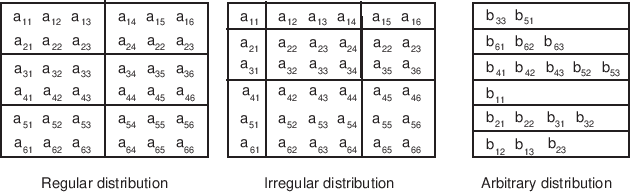
ESMF Grids have several options for data distribution (also referred to as decomposition). As ESMF Grids are cell based, these options are all specified in terms of how the cells in the Grid are broken up between DEs.

The main distribution options are regular, irregular, and arbitrary. A regular distribution is one in which the same number of contiguous grid cells are assigned to each DE in the distributed dimension. An irregular distribution is one in which unequal numbers of contiguous grid cells are assigned to each DE in the distributed dimension. An arbitrary distribution is one in which any grid cell can be assigned to any DE. Any of these distribution options can be applied to any of the grid shapes (i.e., rectangle) or types (i.e., rectilinear). Support for arbitrary distribution is limited in the current version of ESMF.

Figure 7 illustrates options for distribution.

Figure 7: Examples of regular and irregular decomposition of a grid a that is 6x6, and an arbitrary decomposition of a grid b that is 6x3.
\scalebox{0.9}{\includegraphics{GridDecomps}}

A distribution can also be specified using the DistGrid, by passing object into a Grid create call.


19.1.5 Grid Coordinates

Grid Tiles can have uniform, rectilinear, or curvilinear coordinates. The coordinates of uniform grids are equally spaced along their axes, and can be fully specified by the coordinates of the two opposing points that define the grid's physical span. The coordinates of rectilinear grids are unequally spaced along their axes, and can be fully specified by giving the spacing of grid points along each axis. The coordinates of curvilinear grids must be specified by giving the explicit set of coordinates for each grid point. Curvilinear grids are often uniform or rectilinear grids that have been warped; for example, to place a pole over a land mass so that it does not affect the computations performed on an ocean model grid. Figure 8 shows examples of each type of grid.

Figure 8: Types of logically rectangular grid tiles. Red circles show the values needed to specify grid coordinates for each type.
\scalebox{0.9}{\includegraphics{LogRectGrids}}

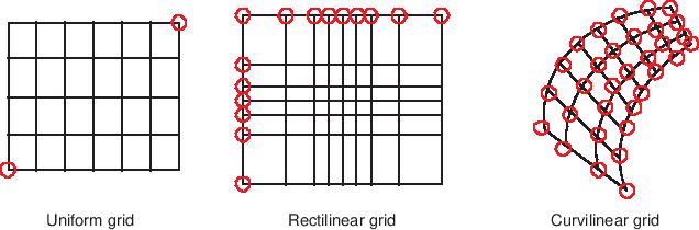
Each of these coordinate types can be set for each of the standard grid shapes described in section 19.1.3.

The table below shows how examples of common single Tile grids fall into this shape and coordinate taxonomy. Note that any of the grids in the table can have a regular or arbitrary distribution.


  Uniform Rectilinear Curvilinear
Sphere Global uniform lat-lon grid Gaussian grid Displaced pole grid
Rectangle Regional uniform lat-lon grid Gaussian grid section Polar stereographic grid section

19.1.6 Coordinate Specification and Generation

There are two ways of specifying coordinates in ESMF. The first way is for the user to set the coordinates. The second way is to take a shortcut and have the framework generate the coordinates.

No ESMF generation routines are currently available.

19.1.7 Staggering

Staggering is a finite difference technique in which the values of different physical quantities are placed at different locations within a grid cell.

The ESMF Grid class supports a variety of stagger locations, including cell centers, corners, and edge centers. The default stagger location in ESMF is the cell center, and cell counts in Grid are based on this assumption. Combinations of the 2D ESMF stagger locations are sufficient to specify any of the Arakawa staggers. ESMF also supports staggering in 3D and higher dimensions. There are shortcuts for standard staggers, and interfaces through which users can create custom staggers.

As a default the ESMF Grid class provides symmetric staggering, so that cell centers are enclosed by cell perimeter (e.g. corner) stagger locations. This means the coordinate arrays for stagger locations other than the center will have an additional element of padding in order to enclose the cell center locations. However, to achieve other types of staggering, the user may alter or eliminate this padding by using the appropriate options when adding coordinates to a Grid.


19.1.8 Masking

Masking is the process whereby parts of a grid can be marked to be ignored during an operation, such as regridding. Masking can be used on a source grid to indicate that certain portions of the grid should not be used to generate regridded data. This is useful, for example, if a portion of the source grid contains unusable values. Masking can also be used on a destination grid to indicate that the portion of the field built on that part of the Grid should not receive regridded data. This is useful, for example, when part of the grid isn't being used (e.g. the land portion of an ocean grid).

ESMF regrid currently supports masking for Fields built on structured Grids and element masking for Fields built on unstructured Meshes. The user may mask out points in the source Field or destination Field or both. To do masking the user sets mask information in the Grid or Mesh upon which the Fields passed into the ESMC_FieldRegridStore() call are built. The srcMaskValues and dstMaskValues arguments to that call can then be used to specify which values in that mask information indicate that a location should be masked out. For example, if dstMaskValues is set to (/1,2/), then any location that has a value of 1 or 2 in the mask information of the Grid or Mesh upon which the destination Field is built will be masked out.

Masking behavior differs slightly between regridding methods. For non-conservative regridding methods (e.g. bilinear or high-order patch), masking is done on points. For these methods, masking a destination point means that that point won't participate in regridding (e.g. won't be interpolated to). For these methods, masking a source point means that the entire source cell using that point is masked out. In other words, if any corner point making up a source cell is masked then the cell is masked. For conservative regridding methods (e.g. first-order conservative) masking is done on cells. Masking a destination cell means that the cell won't participate in regridding (e.g. won't be interpolated to). Similarly, masking a source cell means that the cell won't participate in regridding (e.g. won't be interpolated from). For any type of interpolation method (conservative or non-conservative) the masking is set on the location upon which the Fields passed into the regridding call are built. For example, if Fields built on ESMC_STAGGERLOC_CENTER are passed into the ESMC_FieldRegridStore() call then the masking should also be set on ESMC_STAGGERLOC_CENTER.

19.2 Constants


19.2.1 ESMC_COORDSYS

DESCRIPTION:
A set of values which indicates in which system the coordinates in the Grid are. This value is useful both to indicate to other users the type of the coordinates, but also to control how the coordinates are interpreted in regridding methods (e.g. ESMC_FieldRegridStore()).

The type of this flag is:

type(ESMC_CoordSys_Flag)

The valid values are:

ESMC_COORDSYS_CART
Cartesian coordinate system. In this system, the cartesian coordinates are mapped to the Grid coordinate dimensions in the following order: x,y,z. (E.g. using coordDim=2 in ESMC_GridGetCoord() references the y dimension)

ESMC_COORDSYS_SPH_DEG
Spherical coordinates in degrees. In this system, the spherical coordinates are mapped to the Grid coordinate dimensions in the following order: longitude, latitude, radius. (E.g. using coordDim=2 in ESMC_GridGetCoord() references the latitude dimension) Note, however, that ESMC_FieldRegridStore() currently just supports longitude and latitude (i.e. with this system, only Grids of dimension 2 are supported in the regridding).

ESMC_COORDSYS_SPH_RAD
Spherical coordinates in radians. In this system, the spherical coordinates are mapped to the Grid coordinate dimensions in the following order: longitude, latitude, radius. (E.g. using coordDim=2 in ESMC_GridGetCoord() references the latitude dimension) Note, however, that ESMC_FieldRegridStore() currently just supports longitude and latitude (i.e. with this system, only Grids of dimension 2 are supported in the regridding).


19.2.2 ESMC_GRIDITEM

DESCRIPTION:
The ESMC Grid can contain other kinds of data besides coordinates. This data is referred to as Grid “items”. Some items may be used by ESMC for calculations involving the Grid. The following are the valid values of ESMC_GridItem_Flag.

The type of this flag is:

type(ESMC_GridItem_Flag)

The valid values are:
Item Label Type Restriction Type Default ESMC Uses Controls
ESMC_GRIDITEM_MASK ESMC_TYPEKIND_I4 ESMC_TYPEKIND_I4 YES Masking in Regrid
ESMC_GRIDITEM_AREA NONE ESMC_TYPEKIND_R8 YES Conservation in Regrid


19.2.3 ESMC_GRIDSTATUS

DESCRIPTION:
The ESMC Grid class can exist in two states. These states are present so that the library code can detect if a Grid has been appropriately setup for the task at hand. The following are the valid values of ESMC_GRIDSTATUS.

The type of this flag is:

type(ESMC_GridStatus_Flag)

The valid values are:

ESMC_GRIDSTATUS_EMPTY:
Status after a Grid has been created with ESMC_GridEmptyCreate. A Grid object container is allocated but space for internal objects is not. Topology information and coordinate information is incomplete. This object can be used in ESMC_GridEmptyComplete() methods in which additional information is added to the Grid.
ESMC_GRIDSTATUS_COMPLETE:
The Grid has a specific topology and distribution, but incomplete coordinate arrays. The Grid can be used as the basis for allocating a Field, and coordinates can be added via ESMC_GridCoordAdd() to allow other functionality.


19.2.4 ESMC_POLEKIND

DESCRIPTION:
This type describes the type of connection that occurs at the pole when a Grid is created with ESMC_GridCreate1PeriodicDim().

The type of this flag is:

type(ESMC_PoleKind_Flag)

The valid values are:

ESMC_POLEKIND_NONE
No connection at pole.

ESMC_POLEKIND_MONOPOLE
This edge is connected to itself. Given that the edge is n elements long, then element i is connected to element i+n/2.

ESMC_POLEKIND_BIPOLE
This edge is connected to itself. Given that the edge is n elements long, element i is connected to element n-i-1.


19.2.5 ESMC_STAGGERLOC

DESCRIPTION:
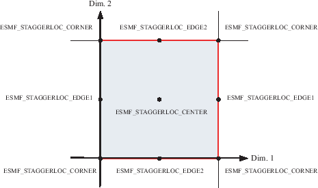
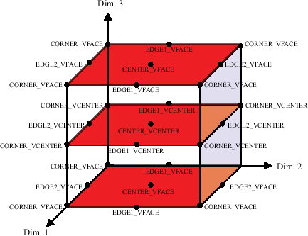
In the ESMC Grid class, data can be located at different positions in a Grid cell. When setting or retrieving coordinate data the stagger location is specified to tell the Grid method from where in the cell to get the data. Although the user may define their own custom stagger locations, ESMC provides a set of predefined locations for ease of use. The following are the valid predefined stagger locations.


Figure 9: 2D Predefined Stagger Locations
\scalebox{0.75}{\includegraphics{GridStaggerLoc2D}}

The 2D predefined stagger locations (illustrated in figure 9) are:

ESMC_STAGGERLOC_CENTER:
The center of the cell.
ESMC_STAGGERLOC_CORNER:
The corners of the cell.
ESMC_STAGGERLOC_EDGE1:
The edges offset from the center in the 1st dimension.
ESMC_STAGGERLOC_EDGE2:
The edges offset from the center in the 2nd dimension.


Figure 10: 3D Predefined Stagger Locations
\scalebox{1.0}{\includegraphics{GridStaggerLoc3D}}

The 3D predefined stagger locations (illustrated in figure 10) are:

ESMC_STAGGERLOC_CENTER_VCENTER:
The center of the 3D cell.
ESMC_STAGGERLOC_CORNER_VCENTER:
Half way up the vertical edges of the cell.
ESMC_STAGGERLOC_EDGE1_VCENTER:
The center of the face bounded by edge 1 and the vertical dimension.
ESMC_STAGGERLOC_EDGE2_VCENTER:
The center of the face bounded by edge 2 and the vertical dimension.
ESMC_STAGGERLOC_CORNER_VFACE:
The corners of the 3D cell.
ESMC_STAGGERLOC_EDGE1_VFACE:
The center of the edges of the 3D cell parallel offset from the center in the 1st dimension.
ESMC_STAGGERLOC_EDGE2_VFACE:
The center of the edges of the 3D cell parallel offset from the center in the 2nd dimension.
ESMC_STAGGERLOC_CENTER_VFACE:
The center of the top and bottom face. The face bounded by the 1st and 2nd dimensions.


19.2.6 ESMC_FILEFORMAT

DESCRIPTION:
This option is used by ESMC_GridCreateFromFile to specify the type of the input grid file.

The type of this flag is:

type(ESMC_FileFormat_Flag)

The valid values are:

ESMC_FILEFORMAT_SCRIP
SCRIP format grid file. The SCRIP format is the format accepted by the SCRIP regridding tool [1]. For Grid creation, files of this type only work when the grid_rank in the file is equal to 2.

ESMC_FILEFORMAT_GRIDSPEC
a single tile grid file comforming with the proposed CF-GRIDSPEC conventions.

19.3 Restrictions and Future Work

19.4 Design and Implementation Notes

19.4.1 Grid Topology

The ESMF_Grid class depends upon the ESMF_DistGrid class for the specification of its topology. That is, when creating a Grid, first an ESMF_DistGrid is created to describe the appropriate index space topology. This decision was made because it seemed redundant to have a system for doing this in both classes. It also seems most appropriate for the machinary for topology creation to be located at the lowest level possible so that it can be used by other classes (e.g. the ESMF_Array class). Because of this, however, the authors recommend that as a natural part of the implementation of subroutines to generate standard grid shapes (e.g. ESMF_GridGenSphere) a set of standard topology generation subroutines be implemented (e.g. ESMF_DistGridGenSphere) for users who want to create a standard topology, but a custom geometry.

19.5 Class API: General Grid Methods

19.5.1 ESMC_GridCreateNoPeriDim - Create a Grid with no periodic dimensions


INTERFACE:

 ESMC_Grid ESMC_GridCreateNoPeriDim(
   ESMC_InterArrayInt *maxIndex,           // in
   enum ESMC_CoordSys_Flag *coordSys,      // in
   enum ESMC_TypeKind_Flag *coordTypeKind, // in
   enum ESMC_IndexFlag *indexflag,         // in
   int *rc                                 // out
 );
RETURN VALUE:
    type(ESMC_Grid)
DESCRIPTION:

This call creates an ESMC_Grid with no periodic dimensions.

The arguments are:

maxIndex
The upper extent of the grid array.
coordSys
The coordinated system of the grid coordinate data. If not specified then defaults to ESMF_COORDSYS_SPH_DEG.
coordTypeKind
The type/kind of the grid coordinate data. If not specified then the type/kind will be 8 byte reals.
indexflag
Indicates the indexing scheme to be used in the new Grid. If not present, defaults to ESMC_INDEX_DELOCAL.
rc
Return code; equals ESMF_SUCCESS if there are no errors.

19.5.2 ESMC_GridCreate1PeriDim - Create a Grid with 1 periodic dimension


INTERFACE:

 ESMC_Grid ESMC_GridCreate1PeriDim(
   ESMC_InterArrayInt *maxIndex,           // in
   ESMC_InterArrayInt *polekindflag,       // in
   int *periodicDim,                       // in
   int *poleDim,                           // in
   enum ESMC_CoordSys_Flag *coordSys,      // in
   enum ESMC_TypeKind_Flag *coordTypeKind, // in
   enum ESMC_IndexFlag *indexflag,         // in
   int *rc                                 // out
 );
RETURN VALUE:
    type(ESMC_Grid)
DESCRIPTION:

This call creates an ESMC_Grid with 1 periodic dimension.

The arguments are:

maxIndex
The upper extent of the grid array.
polekindflag
Two item array which specifies the type of connection which occurs at the pole. polekindflag(1) the connection that occurs at the minimum end of the index dimension. polekindflag(2) the connection that occurs at the maximum end of the index dimension. If not specified, the default is ESMF_POLETYPE_MONOPOLE for both.
periodicDim
The periodic dimension. If not specified, defaults to 1.
poleDim
The dimension at which the poles are located at the ends. If not specified, defaults to 2.
coordSys
The coordinated system of the grid coordinate data. If not specified then defaults to ESMF_COORDSYS_SPH_DEG.
coordTypeKind
The type/kind of the grid coordinate data. If not specified then the type/kind will be 8 byte reals.
indexflag
Indicates the indexing scheme to be used in the new Grid. If not present, defaults to ESMC_INDEX_DELOCAL.
rc
Return code; equals ESMF_SUCCESS if there are no errors.

19.5.3 ESMC_GridCreateCubedSphere - Create a cubed sphere Grid


INTERFACE:

 ESMC_Grid ESMC_GridCreateCubedSphere(
   int *tilesize,                      // in
   ESMC_InterArrayInt *regDecompPTile, // in
   //ESMC_InterArrayInt *decompFlagPTile,  // in
   //ESMC_InterArrayInt *deLabelList,    // in
   //ESMC_DELayout *delayout,            // in
   ESMC_InterArrayInt *staggerLocList,   // in
   const char *name,                   // in
   int *rc);                           // out
RETURN VALUE:
    type(ESMC_Grid)
DESCRIPTION:

Create a six-tile ESMC_Grid for a cubed sphere grid using regular decomposition. Each tile can have different decomposition. The grid coordinates are generated based on the algorithm used by GEOS-5. The tile resolution is defined by tileSize.

The arguments are:

tilesize
The number of elements on each side of the tile of the cubed sphere grid.
regDecompPTile
List of DE counts for each dimension. The second index steps through the tiles. The total deCount is determined as the sum over the products of regDecompPTile elements for each tile. By default every tile is decomposed in the same way. If the total PET count is less than 6, one tile will be assigned to one DE and the DEs will be assigned to PETs sequentially, therefore, some PETs may have more than one DE. If the total PET count is greater than 6, the total number of DEs will be a multiple of 6 and less than or equal to the total PET count. For instance, if the total PET count is 16, the total DE count will be 12 with each tile decomposed into 1x2 blocks. The 12 DEs are mapped to the first 12 PETs and the remaining 4 PETs have no DEs locally, unless an optional delayout is provided.
staggerLocList
The list of stagger locations to fill with coordinates. Only ESMF_STAGGERLOC_CENTER and ESMF_STAGGERLOC_CORNER are supported. If not present, no coordinates will be added or filled.
name
The name of the ESMC_Grid.
rc
Return code; equals ESMF_SUCCESS if there are no errors.

19.5.4 ESMC_GridCreateFromFile - Create a Grid from a NetCDF file specification.


INTERFACE:

 ESMC_Grid ESMC_GridCreateFromFile(const char *filename, int fileTypeFlag, 
                   int *regDecomp, int *decompflag,
                   int *isSphere, ESMC_InterArrayInt *polekindflag,
                   int *addCornerStagger,
                   int *addUserArea, enum ESMC_IndexFlag *indexflag,
                   int *addMask, const char *varname,
                   const char **coordNames, int *rc);
RETURN VALUE:
    type(ESMC_Grid)
DESCRIPTION:

This function creates a ESMC_Grid object from the specification in a NetCDF file.

The arguments are:

filename
The NetCDF Grid filename.
fileTypeFlag
The Grid file format, please see Section 19.2.6 for a list of valid options.
regDecomp
A 2 element array specifying how the grid is decomposed. Each entry is the number of decounts for that dimension. The total decounts cannot exceed the total number of PETs. In other word, at most one DE is allowed per processor. If not specified, the default decomposition will be petCountx1.
[decompflag]
List of decomposition flags indicating how each dimension of the tile is to be divided between the DEs. The default setting is ESMF_DECOMP_BALANCED in all dimensions. Please see Section 33.3 for a full description of the possible options.
[isSphere]
Set to 1 for a spherical grid, or 0 for regional. Defaults to 1.
polekindflag
Two item array which specifies the type of connection which occurs at the pole. polekindflag(1) the connection that occurs at the minimum end of the index dimension. polekindflag(2) the connection that occurs at the maximum end of the index dimension. If not specified, the default is ESMF_POLETYPE_MONOPOLE for both.
[addCornerStagger]
Set to 1 to use the information in the grid file to add the Corner stagger to the Grid. The coordinates for the corner stagger are required for conservative regridding. If not specified, defaults to 0.
[addUserArea]
Set to 1 to read in the cell area from the Grid file; otherwise, ESMF will calculate it. This feature is only supported when the grid file is in the SCRIP format.
indexflag
Indicates the indexing scheme to be used in the new Grid. If not present, defaults to ESMC_INDEX_DELOCAL.
[addMask]
Set to 1 to generate the mask using the missing_value attribute defined in 'varname'. This flag is only needed when the grid file is in the GRIDSPEC format.
[varname]
If addMask is non-zero, provide a variable name stored in the grid file and the mask will be generated using the missing value of the data value of this variable. The first two dimensions of the variable has to be the longitude and the latitude dimension and the mask is derived from the first 2D values of this variable even if this data is 3D, or 4D array.
[coordNames]
A two-element array containing the longitude and latitude variable names in a GRIDSPEC file if there are multiple coordinates defined in the file.
[rc]
Return code; equals ESMF_SUCCESS if there are no errors.

19.5.5 ESMC_GridDestroy - Destroy a Grid


INTERFACE:

 int ESMC_GridDestroy(
   ESMC_Grid *grid             // in
 );
RETURN VALUE:
    Return code; equals ESMF_SUCCESS if there are no errors.
DESCRIPTION:

Destroy the Grid.

The arguments are:

grid
Grid object whose memory is to be freed.

19.5.6 ESMC_GridAddItem - Add items to a Grid


INTERFACE:

 int ESMC_GridAddItem(
   ESMC_Grid grid,                   // in
   enum ESMC_GridItem_Flag itemflag, // in
   enum ESMC_StaggerLoc staggerloc   // in
 );
RETURN VALUE:
    Return code; equals ESMF_SUCCESS if there are no errors.
DESCRIPTION:

Add an item (e.g. a mask) to the Grid.

The arguments are:

grid
Grid object to which the coordinates will be added
itemflag
The grid item to add.
staggerloc
The stagger location to add.

19.5.7 ESMC_GridGetItem - Get item from a Grid


INTERFACE:

 void * ESMC_GridGetItem(
   ESMC_Grid grid,                         // in
   enum ESMC_GridItem_Flag itemflag,       // in
   enum ESMC_StaggerLoc staggerloc,        // in
   int *localDE,                           // in
   int *rc                                 // out
 );
RETURN VALUE:
    A pointer to the item data.
DESCRIPTION:

Get a pointer to item data (e.g. mask data) in the Grid.

The arguments are:

grid
Grid object from which to obtain the coordinates.
itemflag
The grid item to add.
staggerloc
The stagger location to add.
localDE
The local decompositional element. If not present, defaults to 0.
rc
Return code; equals ESMF_SUCCESS if there are no errors.

19.5.8 ESMC_GridAddCoord - Add coordinates to a Grid


INTERFACE:

 int ESMC_GridAddCoord(
   ESMC_Grid grid,                   // in
   enum ESMC_StaggerLoc staggerloc   // in
 );
RETURN VALUE:
    Return code; equals ESMF_SUCCESS if there are no errors.
DESCRIPTION:

Add coordinates to the Grid.

The arguments are:

grid
Grid object to which the coordinates will be added
staggerloc
The stagger location to add.

19.5.9 ESMC_GridGetCoord - Get coordinates from a Grid


INTERFACE:

 void * ESMC_GridGetCoord(
   ESMC_Grid grid,                         // in
   int coordDim,                           // in
   enum ESMC_StaggerLoc staggerloc,        // in
   int *localDE,
   int *exclusiveLBound,                   // out
   int *exclusiveUBound,                   // out
   int *rc                                 // out
 );
RETURN VALUE:
    A pointer to coordinate data in the Grid.
DESCRIPTION:

Get a pointer to coordinate data in the Grid.

The arguments are:

grid
Grid object from which to obtain the coordinates.
coordDim
The coordinate dimension from which to get the data.
staggerloc
The stagger location to add.
localDE
The local decompositional element. If not present, defaults to 0.
exclusiveLBound
Upon return this holds the lower bounds of the exclusive region. This bound must be allocated to be of size equal to the coord dimCount.
exclusiveUBound
Upon return this holds the upper bounds of the exclusive region. This bound must be allocated to be of size equal to the coord dimCount.
rc
Return code; equals ESMF_SUCCESS if there are no errors.

19.5.10 ESMC_GridGetCoordBounds - Get coordinate bounds from a Grid


INTERFACE:

 int ESMC_GridGetCoordBounds(
   ESMC_Grid grid,                         // in
   enum ESMC_StaggerLoc staggerloc,        // in
   int *localDE,                           // in
   int *exclusiveLBound,                   // out
   int *exclusiveUBound,                   // out
   int *rc                                 // out
 );
RETURN VALUE:
    Return code; equals ESMF_SUCCESS if there are no errors.
DESCRIPTION:

Get coordinates bounds from the Grid.

The arguments are:

grid
Grid object from which to obtain the coordinates.
staggerloc
The stagger location to add.
localDE
The local decompositional element. If not present, defaults to 0.
exclusiveLBound
Upon return this holds the lower bounds of the exclusive region. This bound must be allocated to be of size equal to the coord dimCount.
exclusiveUBound
Upon return this holds the upper bounds of the exclusive region. This bound must be allocated to be of size equal to the coord dimCount.
rc
Return code; equals ESMF_SUCCESS if there are no errors.

20 Mesh Class

20.1 Description

Unstructured grids are commonly used in the computational solution of Partial Differential equations. These are especially useful for problems that involve complex geometry, where using the less flexible structured grids can result in grid representation of regions where no computation is needed. Finite element and finite volume methods map naturally to unstructured grids and are used commonly in hydrology, ocean modeling, and many other applications.

In order to provide support for application codes using unstructured grids, the ESMF library provides a class for representing unstructured grids called the Mesh. Fields can be created on a Mesh to hold data. In Fortran, Fields created on a Mesh can also be used as either the source or destination or both of an interpolation (i.e. an ESMF_FieldRegridStore() call). This capability is currently not supported with the C interface, however, if the C Field is passed via a State to a component written in Fortran then the regridding can be performed there. The rest of this section describes the Mesh class and how to create and use them in ESMF.

20.1.1 Mesh Representation in ESMF

A Mesh in ESMF is described in terms of nodes and elements. A node is a point in space which represents where the coordinate information in a Mesh is located. An element is a higher dimensional shape constructed of nodes. Elements give a Mesh its shape and define the relationship of the nodes to one another. Field data may be located on a Mesh's nodes.

20.1.2 Supported Meshes

The range of Meshes supported by ESMF are defined by several factors: dimension, element types, and distribution.

ESMF currently only supports Meshes whose number of coordinate dimensions (spatial dimension) is 2 or 3. The dimension of the elements in a Mesh (parametric dimension) must be less than or equal to the spatial dimension, but also must be either 2 or 3. This means that an ESMF mesh may be either 2D elements in 2D space, 3D elements in 3D space, or a manifold constructed of 2D elements embedded in 3D space.

ESMF currently supports two types of elements for each Mesh parametric dimension. For a parametric dimension of 2 the supported element types are triangles or quadrilaterals. For a parametric dimension of 3 the supported element types are tetrahedrons and hexahedrons. See Section 20.2.1 for diagrams of these. The Mesh supports any combination of element types within a particular dimension, but types from different dimensions may not be mixed, for example, a Mesh cannot be constructed of both quadrilaterals and tetrahedra.

ESMF currently only supports distributions where every node on a PET must be a part of an element on that PET. In other words, there must not be nodes without an element on a PET.

20.2 Constants


20.2.1 ESMC_MESHELEMTYPE

DESCRIPTION:
An ESMF Mesh can be constructed from a combination of different elements. The type of elements that can be used in a Mesh depends on the Mesh's parametric dimension, which is set during Mesh creation. The following are the valid Mesh element types for each valid Mesh parametric dimension (2D or 3D) .


                     3                          4 ---------- 3
                    / \                         |            |  
                   /   \                        |            |
                  /     \                       |            |
                 /       \                      |            |
                /         \                     |            |
               1 --------- 2                    1 ---------- 2

           ESMC_MESHELEMTYPE_TRI            ESMC_MESHELEMTYPE_QUAD

2D element types (numbers are the order for elementConn during 
                  Mesh create)

For a Mesh with parametric dimension of 2 the valid element types (illustrated above) are:

Element Type Number of Nodes Description
ESMC_MESHELEMTYPE_TRI 3 A triangle
ESMC_MESHELEMTYPE_QUAD 4 A quadrilateral (e.g. a rectangle)


                 3                               8---------------7
                /|\                             /|              /|
               / | \                           / |             / |
              /  |  \                         /  |            /  |
             /   |   \                       /   |           /   |
            /    |    \                     5---------------6    |
           4-----|-----2                    |    |          |    |
            \    |    /                     |    4----------|----3
             \   |   /                      |   /           |   /
              \  |  /                       |  /            |  /
               \ | /                        | /             | /
                \|/                         |/              |/
                 1                          1---------------2

       ESMC_MESHELEMTYPE_TETRA             ESMC_MESHELEMTYPE_HEX  

3D element types (numbers are the order for elementConn during 
                  Mesh create)

For a Mesh with parametric dimension of 3 the valid element types (illustrated above) are:

Element Type Number of Nodes Description
ESMC_MESHELEMTYPE_TETRA 4 A tetrahedron (CAN'T BE USED IN REGRID)
ESMC_MESHELEMTYPE_HEX 8 A hexahedron (e.g. a cube)


20.2.2 ESMF_FILEFORMAT

DESCRIPTION:
This option is used by ESMF_MeshCreate to specify the type of the input grid file.

The type of this flag is:

type(ESMF_FileFormat_Flag)

The valid values are:

ESMF_FILEFORMAT_SCRIP
SCRIP format grid file. The SCRIP format is the format accepted by the SCRIP regridding tool [1]. For Mesh creation, files of this type only work when the grid_rank in the file is equal to 1.

ESMF_FILEFORMAT_ESMFMESH
ESMF unstructured grid file format. This format was developed by the ESMF team to match the capabilities of the Mesh class and to be efficient to convert to that class.

ESMF_FILEFORMAT_UGRID
CF-convention unstructured grid file format. This format is a proposed extension to the CF-conventions for unstructured grid data model. Currently, only the 2D flexible mesh topology is supported in ESMF.

20.3 Class API


20.3.1 ESMC_MeshAddElements - Add elements to a Mesh


INTERFACE:

 int ESMC_MeshAddElements(
   ESMC_Mesh mesh,           // inout
   int  elementCount,        // in
   int *elementIds,          // in
   int *elementTypes,        // in
   int *elementConn,         // in
   int *elementMask,         // in
   double *elementArea,      // in
   double *elementCoords     // in
 );
RETURN VALUE:
    Return code; equals ESMF_SUCCESS if there are no errors.
DESCRIPTION:

This call is the third and last part of the three part mesh create sequence and should be called after the mesh is created with ESMF_MeshCreate() (20.3.3) and after the nodes are added with ESMF_MeshAddNodes() (20.3.2). This call adds the elements to the mesh and finalizes the create. After this call the Mesh is usable, for example a Field may be built on the created Mesh object and this Field may be used in a ESMF_FieldRegridStore() call.

The parameters to this call elementIds, elementTypes, and elementConn describe the elements to be created. The description for a particular element lies at the same index location in elementIds and elementTypes. Each entry in elementConn consists of the list of nodes used to create that element, so the connections for element $e$ in the elementIds array will start at $number\_of\_nodes\_in\_element(1) + number\_of\_nodes\_in\_element(2) +
\cdots + number\_of\_nodes\_in\_element(e-1) + 1$ in elementConn.

mesh
Mesh object.
elementCount
The number of elements on this PET.
elementIds
An array containing the global ids of the elements to be created on this PET. This input consists of a 1D array of size elementCount.
elementTypes
An array containing the types of the elements to be created on this PET. The types used must be appropriate for the parametric dimension of the Mesh. Please see Section 20.2.1 for the list of options. This input consists of a 1D array of size elementCount.
elementConn
An array containing the indexes of the sets of nodes to be connected together to form the elements to be created on this PET. The entries in this list are NOT node global ids, but rather each entry is a local index (1 based) into the list of nodes which were created on this PET by the previous ESMC_MeshAddNodes() call. In other words, an entry of 1 indicates that this element contains the node described by nodeIds(1), nodeCoords(1), etc. passed into the ESMC_MeshAddNodes() call on this PET. It is also important to note that the order of the nodes in an element connectivity list matters. Please see Section 20.2.1 for diagrams illustrating the correct order of nodes in a element. This input consists of a 1D array with a total size equal to the sum of the number of nodes in each element on this PET. The number of nodes in each element is implied by its element type in elementTypes. The nodes for each element are in sequence in this array (e.g. the nodes for element 1 are elementConn(1), elementConn(2), etc.).
[elementMask]
An array containing values which can be used for element masking. Which values indicate masking are chosen via the srcMaskValues or dstMaskValues arguments to ESMF_FieldRegridStore() call. This input consists of a 1D array the size of the number of elements on this PET. If not specified (i.e. NULL is passed in), then no masking will occur.
[elementArea]
An array containing element areas. This input consists of a 1D array the size of the number of elements on this PET. If not specified (i.e. NULL is passed in), the element areas are internally calculated.
[elementCoords]
An array containing the physical coordinates of the elements to be created on this PET. This input consists of a 1D array the size of the number of elements on this PET times the Mesh's spatial dimension (spatialDim). The coordinates in this array are ordered so that the coordinates for an element lie in sequence in memory. (e.g. for a Mesh with spatial dimension 2, the coordinates for element 1 are in elementCoords(1) and elementCoords(2), the coordinates for element 2 are in elementCoords(3) and elementCoords(4), etc.).


20.3.2 ESMC_MeshAddNodes - Add nodes to a Mesh


INTERFACE:

 int ESMC_MeshAddNodes(
   ESMC_Mesh mesh,          // inout
   int nodeCount,           // in
   int *nodeIds,            // in
   double *nodeCoords,      // in
   int *nodeOwners          // in
 );
RETURN VALUE:
    Return code; equals ESMF_SUCCESS if there are no errors.
DESCRIPTION:

This call is the second part of the three part mesh create sequence and should be called after the mesh's dimensions are set using ESMC_MeshCreate(). This call adds the nodes to the mesh. The next step is to call ESMC_MeshAddElements() (20.3.3).

The parameters to this call nodeIds, nodeCoords, and nodeOwners describe the nodes to be created on this PET. The description for a particular node lies at the same index location in nodeIds and nodeOwners. Each entry in nodeCoords consists of spatial dimension coordinates, so the coordinates for node $n$ in the nodeIds array will start at $(n-1)*spatialDim+1$.

mesh
Mesh object.
nodeCount
The number of nodes on this PET.
nodeIds
An array containing the global ids of the nodes to be created on this PET. This input consists of a 1D array the size of the number of nodes on this PET (i.e. nodeCount).
nodeCoords
An array containing the physical coordinates of the nodes to be created on this PET. The coordinates in this array are ordered so that the coordinates for a node lie in sequence in memory. (e.g. for a Mesh with spatial dimension 2, the coordinates for node 1 are in nodeCoords(0) and nodeCoords(1), the coordinates for node 2 are in nodeCoords(2) and nodeCoords(3), etc.). This input consists of a 1D array the size of nodeCount times the Mesh's spatial dimension (spatialDim).
nodeOwners
An array containing the PETs that own the nodes to be created on this PET. If the node is shared with another PET, the value may be a PET other than the current one. Only nodes owned by this PET will have PET local entries in a Field created on the Mesh. This input consists of a 1D array the size of the number of nodes on this PET (i.e. nodeCount).


20.3.3 ESMC_MeshCreate - Create a Mesh as a 3 step process


INTERFACE:

 ESMC_Mesh ESMC_MeshCreate(
   int parametricDim,         // in
   int spatialDim,            // in
   enum ESMC_CoordSys_Flag *coordSys, // in
   int *rc                    // out
 );
RETURN VALUE:
    type(ESMC_Mesh)         :: ESMC_MeshCreate
DESCRIPTION:

This call is the first part of the three part mesh create sequence. This call sets the dimension of the elements in the mesh (parametricDim) and the number of coordinate dimensions in the mesh (spatialDim). The next step is to call ESMC_MeshAddNodes() (20.3.2) to add the nodes and then ESMC_MeshAddElements() (20.3.1) to add the elements and finalize the mesh.

The arguments are:

parametricDim
Dimension of the topology of the Mesh. (E.g. a mesh constructed of squares would have a parametric dimension of 2, whereas a Mesh constructed of cubes would have one of 3.)
spatialDim
The number of coordinate dimensions needed to describe the locations of the nodes making up the Mesh. For a manifold, the spatial dimension can be larger than the parametric dim (e.g. the 2D surface of a sphere in 3D space), but it can't be smaller.
[coordSys]
Set the coordinate system of the mesh. If not specified, then defaults to ESMC_COORDSYS_SPH_DEG.
rc
Return code; equals ESMF_SUCCESS if there are no errors.


20.3.4 ESMC_MeshCreateFromFile - Create a Mesh from a NetCDF grid file


INTERFACE:

 ESMC_Mesh ESMC_MeshCreateFromFile(
                                   const char *filename, // in (required)
                                   int fileTypeFlag,     // in (required)
                                   int *convertToDual,   // in (optional)
                                   int *addUserArea,     // in (optional)
                                   const char *meshname, // in (optional)
                                   int *maskFlag,        // in (optional)
                                   const char *varname,  // in (optional)
                                   int *rc               // out
 );
RETURN VALUE:
    type(ESMC_Mesh)         :: ESMC_MeshCreateFromFile
DESCRIPTION:

Method to create a Mesh object from a NetCDF file in either SCRIP, UGRID, or ESMF file formats.

The required arguments are:

filename
The name of the grid file
filetypeflag
The file type of the grid file to be read, please see Section 20.2.2 for a list of valid options.
[convertToDual]
if 1, the mesh will be converted to its dual. If not specified, defaults to 0. Converting to dual is only supported with file type ESMF_FILEFORMAT_SCRIP.
[addUserArea]
if 1, the cell area will be read in from the GRID file. This feature is only supported when the grid file is in the SCRIP or ESMF format. If not specified, defaults to 0.
[meshname]
The dummy variable for the mesh metadata in the UGRID file if the filetypeflag is ESMF_FILEFORMAT_UGRID. If not specified, defaults to empty string.
[maskFlag]
An enumerated integer that, if specified, tells whether a mask in a UGRID file should be defined on the nodes (MeshLoc.NODE) or elements (MeshLoc.ELEMENT) of the mesh. If specified, generate the mask using the missing_value attribute defined in 'varname'. This flag is only supported when the grid file is in the UGRID format. If not specified, defaults to no mask.
[varname]
If maskFlag is specified, provide a variable name stored in the UGRID file and the mask will be generated using the missing value of the data value of this variable. The first two dimensions of the variable has to be the the longitude and the latitude dimension and the mask is derived from the first 2D values of this variable even if this data is 3D, or 4D array. If not specified, defaults to empty string.
[rc]
Return code; equals ESMF_SUCCESS if there are no errors.


20.3.5 ESMC_MeshGetCoord - Get lat/lon coordinates from a Mesh


INTERFACE:

 void ESMC_MeshGetCoord(
                          ESMC_Mesh mesh_in, // in (required)
                          double *nodeCoord, // out
                          int *num_nodes,    // out
                          int *num_dims,     // out
                          int *rc            // out
                          );
RETURN VALUE:
    None
DESCRIPTION:

This call returns the node coordinates of the given ESMC_Mesh in the provided nodeCoord buffer of doubles. At completion, this buffer is a 1-D array with the coordinates for a given node in adjacent indices. For example, for $d$-dimensional coordinates, the first $d$ values in the returned array are the coordinates for the first node, the second $d$ values are the coordinates for the second node, etc.

The arguments are:

mesh_in
Mesh object.
nodeCoord
Pointer to doubles. The node coordinates are returned here.
num_nodes
Pointer to an integer. The number of nodes found in the input Mesh is returned here.
num_dims
Pointer to an integer. The number of coordinate dimensions is returned here.
rc
Return code; equals ESMF_SUCCESS if there are no errors.


20.3.6 ESMC_MeshGetElemCoord - Get lat/lon element center coordinates from a Mesh


INTERFACE:

 void ESMC_MeshGetElemCoord(
                          ESMC_Mesh mesh_in, // in (required)
                          double *elemCoord, // out
                          int *num_elems,    // out
                          int *num_dims,     // out
                          int *rc            // out
                          );
RETURN VALUE:
    None
DESCRIPTION:

This call returns the element coordinates of the given ESMC_Mesh in the provided elemCoord buffer of doubles. At completion, this buffer is a 1-D array with the coordinates for a given element in adjacent indices. For example, for $d$-dimensional coordinates, the first $d$ values in the returned array are the coordinates for the first element, the second $d$ values are the coordinates for the second element, etc.

The arguments are:

mesh_in
Mesh object.
elemCoord
Pointer to doubles. The element coordinates are returned here.
num_elems
Pointer to an integer. The number of elements found in the input Mesh is returned here.
num_dims
Pointer to an integer. The number of coordinate dimensions is returned here.
rc
Return code; equals ESMF_SUCCESS if there are no errors.

20.3.7 ESMC_MeshGetConnectivity - Get Mesh connectivity


INTERFACE:

 void ESMC_MeshGetConnectivity(
                          ESMC_Mesh mesh_in,     // in (required)
                          double *connCoord,     // out
                          int *nodesPerElem,  // out
                          int *rc                // out
                          );
RETURN VALUE:
    None
DESCRIPTION:

NOTE: At this time the connectivity that is returned from this call is not necessarily in the same format as how it was passed into the creation routine.

This call returns the connectivity of the given ESMC_Mesh in the provided connCoord buffer of doubles. At completion, this buffer is a 1-D array with the coordinates for the nodes of a given element in counterclockwise order. The /tt nodesPerElem buffer of integers contains the number of nodes to expect per element.

The arguments are:

mesh_in
Mesh object.
connCoord
Pointer to doubles. The connectivity is returned here.
nodesPerElem
Pointer to integers. The number of nodes in each element.
rc
Return code; equals ESMF_SUCCESS if there are no errors.

20.3.8 ESMC_MeshDestroy - Destroy a Mesh


INTERFACE:

 int ESMC_MeshDestroy(
   ESMC_Mesh *mesh             // in
 );
RETURN VALUE:
    Return code; equals ESMF_SUCCESS if there are no errors.
DESCRIPTION:

Destroy the Mesh. This call removes all internal memory associated with mesh. After this call mesh will no longer be usable.

The arguments are:

mesh
Mesh object whose memory is to be freed.

20.3.9 ESMC_MeshFreeMemory - Remove a Mesh and its memory


INTERFACE:

 int ESMC_MeshFreeMemory(
   ESMC_Mesh mesh            // in
 );
RETURN VALUE:
    Return code; equals ESMF_SUCCESS if there are no errors.
DESCRIPTION:

This call removes the portions of mesh which contain connection and coordinate information. After this call, Fields build on mesh will no longer be usable as part of an ESMF_FieldRegridStore() operation. However, after this call Fields built on mesh can still be used in an ESMF_FieldRegrid() operation if the routehandle was generated beforehand. New Fields may also be built on mesh after this call.

The arguments are:

mesh
Mesh object whose memory is to be freed.

20.3.10 ESMC_MeshGetLocalElementCount - Get the number of elements in a Mesh on the current PET


INTERFACE:

 int ESMC_MeshGetLocalElementCount(
   ESMC_Mesh mesh,           // in
   int *elementCount         // out
 );
RETURN VALUE:
    Return code; equals ESMF_SUCCESS if there are no errors.
DESCRIPTION:

Query the number of elements in a mesh on the local PET. The arguments are:

mesh
The mesh
elementCount
The number of elements on this PET.

20.3.11 ESMC_MeshGetLocalNodeCount - Get the number of nodes in a Mesh on the current PET


INTERFACE:

 int ESMC_MeshGetLocalNodeCount(
   ESMC_Mesh mesh,          // in
   int *nodeCount           // out
 );
RETURN VALUE:
    Return code; equals ESMF_SUCCESS if there are no errors.
DESCRIPTION:

Query the number of nodes in a mesh on the local PET. The arguments are:

mesh
The mesh
nodeCount
The number of nodes on this PET.

20.3.12 ESMC_MeshGetOwnedElementCount - Get the number of elements in a Mesh owned by the current PET


INTERFACE:

 int ESMC_MeshGetOwnedElementCount(
   ESMC_Mesh mesh,           // in
   int *elementCount         // out
 );
RETURN VALUE:
    Return code; equals ESMF_SUCCESS if there are no errors.
DESCRIPTION:

Query the number of elements in a mesh owned by the local PET. This number will be equal or less than the local element count. The arguments are:

mesh
The mesh
elementCount
The number of elements owned by this PET.

20.3.13 ESMC_MeshGetOwnedNodeCount - Get the number of nodes in a Mesh owned by the current PET


INTERFACE:

 int ESMC_MeshGetOwnedNodeCount(
   ESMC_Mesh mesh,          // in
   int *nodeCount           // out
 );
RETURN VALUE:
    Return code; equals ESMF_SUCCESS if there are no errors.
DESCRIPTION:

Query the number of nodes in a mesh owned by the local PET. This number will be equal or less than the local node count. The arguments are:

mesh
The mesh
nodeCount
The number of nodes owned by this PET.

21 XGrid Class

21.1 Description

An exchange grid represents the 2D boundary layer usually between the atmosphere on one side and ocean and land on the other in an Earth system model. There are dynamical and thermodynamical processes on either side of the boundary layer and on the boundary layer itself. The boundary layer exchanges fluxes from either side and adjusts boundary conditions for the model components involved. For climate modeling, it is critical that the fluxes transferred by the boundary layer are conservative.

The ESMF exchange grid is implemented as the ESMC_XGrid class. Internally it's represented by a collection of the intersected cells between atmosphere and ocean/land[3] grids. These polygonal cells can have irregular shapes and can be broken down into triangles facilitating a finite element approach.

Through the C API there is one way to create an ESMC_XGrid object from user supplied information. The ESMC_XGrid takes two lists of ESMC_Grid or ESMC_Mesh that represent the model component grids on either side of the exchange grid. From the two lists of ESMC_Grid or ESMC_Mesh, information required for flux exchange calculation between any pair of the model components from either side of the exchange grid is computed. In addition, the internal representation of the ESMC_XGrid is computed and can be optionally stored as an ESMC_Mesh. This internal representation is the collection of the intersected polygonal cells as a result of merged ESMC_Meshes from both sides of the exchange grid. ESMC_Field can be created on the ESMC_XGrid and used for weight generation and regridding as the internal representation in the ESMC_XGrid has a complete geometrical description of the exchange grid.

Once an ESMC_XGrid has been created, information describing it (e.g. cell areas, mesh representation, etc.) can be retrieved from the object using a set of get calls (e.g. ESMC_XGridGetElementArea()). The full extent of these can be found in the API section below.

21.2 Restrictions and Future Work

21.2.1 Restrictions and Future Work

  1. CAUTION: Any Grid or Mesh pair picked from the A side and B side of the XGrid cannot point to the same Grid or Mesh in memory on a local PET. This prevents Regrid from selecting the right source and destination grid automatically to calculate the regridding routehandle. It's okay for the Grid and Mesh to have identical topological and geographical properties as long as they are stored in different memory.

21.3 Design and Implementation Notes

  1. The XGrid class is implemented in Fortran, and as such is defined inside the framework by a XGrid derived type and a set of subprograms (functions and subroutines) which operate on that derived type. The XGrid class contains information needed to create Grid, Field, and communication routehandle.

  2. XGrid follows the framework-wide convention of the unison creation and operation rule: All PETs which are part of the currently executing VM must create the same XGrids at the same point in their execution. In addition to the unison rule, XGrid creation also performs inter-PET communication within the current executing VM.

21.4 Class API

21.4.1 ESMC_XGridCreate - Create an XGrid


INTERFACE:

   ESMC_XGrid ESMC_XGridCreate(
                               int sideAGridCount,  ESMC_Grid *sideAGrid, // in
                               int sideAMeshCount,  ESMC_Mesh *sideAMesh, // in
                               int sideBGridCount,  ESMC_Grid *sideBGrid, // in
                               int sideBMeshCount,  ESMC_Mesh *sideBMesh, // in
                               ESMC_InterArrayInt *sideAGridPriority,     // in
                               ESMC_InterArrayInt *sideAMeshPriority,     // in
                               ESMC_InterArrayInt *sideBGridPriority,     // in
                               ESMC_InterArrayInt *sideBMeshPriority,     // in
                               ESMC_InterArrayInt *sideAMaskValues,       // in
                               ESMC_InterArrayInt *sideBMaskValues,       // in
                               int storeOverlay,                          // in
                               int *rc                                    // out
 );
RETURN VALUE:
    Newly created ESMC_XGrid object.
DESCRIPTION:

Create an ESMC_XGrid object from user supplied input: the list of Grids or Meshes on side A and side B, and other optional arguments. A user can supply both Grids and Meshes on one side to create the XGrid. By default, the Grids have a higher priority over Meshes but the order of priority can be adjusted by the optional GridPriority and MeshPriority arguments. The priority order of Grids and Meshes can also be interleaved by rearranging the optional GridPriority and MeshPriority arguments accordingly.

Sparse matrix multiplication coefficients are internally computed and uniquely determined by the Grids or Meshes provided in sideA and sideB. User can supply a single ESMC_Grid or an array of ESMC_Grid on either side of the ESMC_XGrid. For an array of ESMC_Grid or ESMC_Mesh in sideA or sideB, a merging process concatenates all the ESMC_Grids and ESMC_Meshes into a super mesh represented by ESMC_Mesh. The super mesh is then used to compute the XGrid. Grid or Mesh objects in sideA and sideB arguments must have coordinates defined for the corners of a Grid or Mesh cell. XGrid creation can be potentially memory expensive given the size of the input Grid and Mesh objects. By default, the super mesh is not stored to reduce memory usage.

If sideA and sideB have a single Grid or Mesh object, it's erroneous if the two Grids or Meshes are spatially disjoint. It is also erroneous to specify a Grid or Mesh object in sideA or sideB that is spatially disjoint from the ESMC_XGrid.

This call is collective across the current VM. For more details please refer to the description 21.1 of the XGrid class.

The arguments are:

sideAGridCount
The number of Grids in the sideAGrid array.
[sideAGrid]
Parametric 2D Grids on side A, for example, these Grids can be either Cartesian 2D or Spherical.
sideAMeshCount
The number of Meshes in the sideAMesh array.
[sideAMesh]
Parametric 2D Meshes on side A, for example, these Meshes can be either Cartesian 2D or Spherical.
sideBGridCount
The number of Grids in the sideBGrid array.
[sideBGrid]
Parametric 2D Grids on side B, for example, these Grids can be either Cartesian 2D or Spherical.
sideBMeshCount
The number of Meshes in the sideBMesh array.
[sideBMesh]
Parametric 2D Meshes on side B, for example, these Meshes can be either Cartesian 2D or Spherical.
[sideAGridPriority]
Priority array of Grids on sideA during overlay generation. The priority arrays describe the priorities of Grids at the overlapping region. Flux contributions at the overlapping region are computed in the order from the Grid of the highest priority to the lowest priority.
[sideAMeshPriority]
Priority array of Meshes on sideA during overlay generation. The priority arrays describe the priorities of Meshes at the overlapping region. Flux contributions at the overlapping region are computed in the order from the Mesh of the highest priority to the lowest priority.
[sideBGridPriority]
Priority of Grids on sideB during overlay generation The priority arrays describe the priorities of Grids at the overlapping region. Flux contributions at the overlapping region are computed in the order from the Grid of the highest priority to the lowest priority.
[sideBMeshPriority]
Priority array of Meshes on sideB during overlay generation. The priority arrays describe the priorities of Meshes at the overlapping region. Flux contributions at the overlapping region are computed in the order from the Mesh of the highest priority to the lowest priority.
[sideAMaskValues]
Mask information can be set in the Grid (see 19.1.8) or Mesh upon which the Field is built. The sideAMaskValues argument specifies the values in that mask information which indicate a point should be masked out. In other words, a location is masked if and only if the value for that location in the mask information matches one of the values listed in sideAMaskValues. If sideAMaskValues is not specified, no masking on side A will occur.
[sideBMaskValues]
Mask information can be set in the Grid (see 19.1.8) or Mesh upon which the Field is built. The sideBMaskValues argument specifies the values in that mask information which indicate a point should be masked out. In other words, a location is masked if and only if the value for that location in the mask information matches one of the values listed in sideBMaskValues. If sideBMaskValues is not specified, no masking on side B will occur.
storeOverlay
Setting the storeOverlay optional argument to 0. allows a user to bypass storage of the Mesh used to represent the XGrid. Only a DistGrid is stored to allow Field to be built on the XGrid. If the temporary mesh object is of interest, storeOverlay can be set to a value not equal to 0. so a user can retrieve it for future use.
[rc]
Return code; equals ESMF_SUCCESS only if the ESMF_XGrid is created.

21.4.2 ESMC_XGridDestroy - Destroy a XGrid


INTERFACE:

 int ESMC_XGridDestroy(
   ESMC_XGrid *xgrid     // inout
 );
RETURN VALUE:
    Return code; equals ESMF_SUCCESS if there are no errors.
DESCRIPTION:

Releases all resources associated with this ESMC_XGrid. Return code; equals ESMF_SUCCESS if there are no errors.

The arguments are:

xgrid
Destroy contents of this ESMC_XGrid.

21.4.3 ESMC_XGridGetSideAGridCount - Get the number of Grids on side A.


INTERFACE:

 int ESMC_XGridGetSideAGridCount(
   ESMC_XGrid xgrid,     // in
   int *rc               // out
 );
RETURN VALUE:
    The number of Grids on side A.
DESCRIPTION:

Get the number of Grids on side A.

The arguments are:

xgrid
The XGrid from which to get the information.
[rc]
Return code; equals ESMF_SUCCESS if there are no errors.

21.4.4 ESMC_XGridGetSideAMeshCount - Get the number of Meshes on side A.


INTERFACE:

 int ESMC_XGridGetSideAMeshCount(
   ESMC_XGrid xgrid,     // in
   int *rc               // out
 );
RETURN VALUE:
    The number of Meshes on side A.
DESCRIPTION:

Get the number of Meshes on side A.

The arguments are:

xgrid
The XGrid from which to get the information.
[rc]
Return code; equals ESMF_SUCCESS if there are no errors.

21.4.5 ESMC_XGridGetSideBGridCount - Get the number of Grids on side B.


INTERFACE:

 int ESMC_XGridGetSideBGridCount(
   ESMC_XGrid xgrid,     // in
   int *rc               // out
 );
RETURN VALUE:
    The number of Grids on side B.
DESCRIPTION:

Get the number of Grids on side B.

The arguments are:

xgrid
The XGrid from which to get the information.
[rc]
Return code; equals ESMF_SUCCESS if there are no errors.

21.4.6 ESMC_XGridGetSideBMeshCount - Get the number of Meshes on side B.


INTERFACE:

 int ESMC_XGridGetSideBMeshCount(
   ESMC_XGrid xgrid,     // in
   int *rc               // out
 );
RETURN VALUE:
    The number of Meshes on side B.
DESCRIPTION:

Get the number of Meshes on side B.

The arguments are:

xgrid
The XGrid from which to get the information.
[rc]
Return code; equals ESMF_SUCCESS if there are no errors.

21.4.7 ESMC_XGridGetDimCount - Get the dimension of the XGrid.


INTERFACE:

 int ESMC_XGridGetDimCount(
   ESMC_XGrid xgrid,     // in
   int *rc               // out
 );
RETURN VALUE:
    The dimension of the XGrid.
DESCRIPTION:

Get the dimension of the XGrid.

The arguments are:

xgrid
The XGrid from which to get the information.
[rc]
Return code; equals ESMF_SUCCESS if there are no errors.

21.4.8 ESMC_XGridGetElementCount - Get the number of elements in the XGrid.


INTERFACE:

 int ESMC_XGridGetElementCount(
   ESMC_XGrid xgrid,     // in
   int *rc               // out
 );
RETURN VALUE:
       The number of elements in the XGrid.
DESCRIPTION:

Get the number of elements in the XGrid.

The arguments are:

xgrid
The XGrid from which to get the information.
[rc]
Return code; equals ESMF_SUCCESS if there are no errors.

21.4.9 ESMC_XGridGetMesh - Get the Mesh representation of the XGrid.


INTERFACE:

 ESMC_Mesh ESMC_XGridGetMesh(
   ESMC_XGrid xgrid,     // in
   int *rc               // out
 );
RETURN VALUE:
    The ESMC_Mesh object representing the XGrid.
DESCRIPTION:

Get the ESMC_Mesh object representing the XGrid.

The arguments are:

xgrid
The xgrid from which to get the information.
[rc]
Return code; equals ESMF_SUCCESS if there are no errors.

21.4.10 ESMC_XGridGetElementArea - Get the area of elements in the XGrid.


INTERFACE:

 void ESMC_XGridGetElementArea(
   ESMC_XGrid xgrid,     // in
   ESMC_R8 *area,        // out
   int *rc               // out
 );
RETURN VALUE:
       The number of elements in the XGrid.
DESCRIPTION:

Get the number of elements in the XGrid.

The arguments are:

xgrid
The XGrid from which to get the information.
area
An array to fill with element areas. The array must be allocated to size elementCount.
[rc]
Return code; equals ESMF_SUCCESS if there are no errors.

21.4.11 ESMC_XGridGetElementCentroid - Get the centroid of elements in the XGrid.


INTERFACE:

 void ESMC_XGridGetElementCentroid(
   ESMC_XGrid xgrid,     // in
   ESMC_R8 *centroid,    // out
   int *rc               // out
 );
RETURN VALUE:
       The number of elements in the XGrid.
DESCRIPTION:

Get the centroid for each element in the exchange grid.

The arguments are:

xgrid
The XGrid from which to get the information.
centroid
An array to fill with element centroids. The array must be allocated to size elementCount*dimCount.
[rc]
Return code; equals ESMF_SUCCESS if there are no errors.

21.4.12 ESMC_XGridGetSparseMatA2X - Get the sparse matrix that goes from a side A grid to the exchange grid.


INTERFACE:

 void ESMC_XGridGetSparseMatA2X(
                                ESMC_XGrid xgrid,      // in
                                int sideAIndex,        // in
                                int *factorListCount,  // out
                                double **factorList,   // out
                                int **factorIndexList, // out
                                int *rc);
RETURN VALUE:
       N/A
DESCRIPTION:

Get the sparse matrix that goes from a side A grid to the exchange grid.

The arguments are:

xgrid
The XGrid from which to get the information.
sideAIndex
The 0 based index of the Grid/Mesh on side A to get the sparse matrix for. If a priority has been specified for Grids and Meshes, then this index is in priority order. If no priority was specified, then the all the Grids are first followed by all the Meshes in the order they were passed into the XGrid create call.
factorListCount
The size of the sparse matrix.
factorList
A pointer to the list of factors for the requested sparse matrix. The list is of size factorListCount. To save space this is a pointer to the internal xgrid memory for this list. Don't deallocate it.
factorIndexList
A pointer to the list of indices for the requested sparse matrix. The list is of size 2*factorListCount. For each pair of entries in this array: entry 0 is the sequence index in the source grid, and entry 1 is the sequence index in the destination grid. To save space this is a pointer to the internal xgrid memory for this list. Don't deallocate it.
[rc]
Return code; equals ESMF_SUCCESS if there are no errors.

21.4.13 ESMC_XGridGetSparseMatA2X - Get the sparse matrix that goes from the exchange grid to a side A grid.


INTERFACE:

 void ESMC_XGridGetSparseMatX2A(
                                ESMC_XGrid xgrid,      // in
                                int sideAIndex,        // in
                                int *factorListCount,  // out
                                double **factorList,   // out
                                int **factorIndexList, // out
                                int *rc);
RETURN VALUE:
       N/A
DESCRIPTION:

Get the sparse matrix that goes from the exchange grid to a side A grid.

The arguments are:

xgrid
The XGrid from which to get the information.
sideAIndex
The 0 based index of the Grid/Mesh on side A to get the sparse matrix for. If a priority has been specified for Grids and Meshes, then this index is in priority order. If no priority was specified, then the all the Grids are first followed by all the Meshes in the order they were passed into the XGrid create call.
factorListCount
The size of the sparse matrix.
factorList
A pointer to the list of factors for the requested sparse matrix. The list is of size factorListCount. To save space this is a pointer to the internal xgrid memory for this list. Don't deallocate it.
factorIndexList
A pointer to the list of indices for the requested sparse matrix. The list is of size 2*factorListCount. For each pair of entries in this array: entry 0 is the sequence index in the source grid, and entry 1 is the sequence index in the destination grid. To save space this is a pointer to the internal xgrid memory for this list. Don't deallocate it.
[rc]
Return code; equals ESMF_SUCCESS if there are no errors.

21.4.14 ESMC_XGridGetSparseMatB2X - Get the sparse matrix that goes from a side B grid to the exchange grid.


INTERFACE:

 void ESMC_XGridGetSparseMatB2X(
                                ESMC_XGrid xgrid,      // in
                                int sideBIndex,        // in
                                int *factorListCount,  // out
                                double **factorList,   // out
                                int **factorIndexList, // out
                                int *rc);
RETURN VALUE:
       N/A
DESCRIPTION:

Get the sparse matrix that goes from a side B grid to the exchange grid.

The arguments are:

xgrid
The XGrid from which to get the information.
sideBIndex
The 0 based index of the Grid/Mesh on side B to get the sparse matrix for. If a priority has been specified for Grids and Meshes, then this index is in priority order. If no priority was specified, then the all the Grids are first followed by all the Meshes in the order they were passed into the XGrid create call.
factorListCount
The size of the sparse matrix.
factorList
A pointer to the list of factors for the requested sparse matrix. The list is of size factorListCount. To save space this is a pointer to the internal xgrid memory for this list. Don't deallocate it.
factorIndexList
A pointer to the list of indices for the requested sparse matrix. The list is of size 2*factorListCount. For each pair of entries in this array: entry 0 is the sequence index in the source grid, and entry 1 is the sequence index in the destination grid. To save space this is a pointer to the internal xgrid memory for this list. Don't deallocate it.
[rc]
Return code; equals ESMF_SUCCESS if there are no errors.

21.4.15 ESMC_XGridGetSparseMatB2X - Get the sparse matrix that goes from the exchange grid to a side B grid.


INTERFACE:

 void ESMC_XGridGetSparseMatX2B(
                                ESMC_XGrid xgrid,      // in
                                int sideBIndex,        // in
                                int *factorListCount,  // out
                                double **factorList,   // out
                                int **factorIndexList, // out
                                int *rc);
RETURN VALUE:
       N/A
DESCRIPTION:

Get the sparse matrix that goes from the exchange grid to a side B grid.

The arguments are:

xgrid
The XGrid from which to get the information.
sideBIndex
The 0 based index of the Grid/Mesh on side B to get the sparse matrix for. If a priority has been specified for Grids and Meshes, then this index is in priority order. If no priority was specified, then the all the Grids are first followed by all the Meshes in the order they were passed into the XGrid create call.
factorListCount
The size of the sparse matrix.
factorList
A pointer to the list of factors for the requested sparse matrix. The list is of size factorListCount. To save space this is a pointer to the internal xgrid memory for this list. Don't deallocate it.
factorIndexList
A pointer to the list of indices for the requested sparse matrix. The list is of size 2*factorListCount. For each pair of entries in this array: entry 0 is the sequence index in the source grid, and entry 1 is the sequence index in the destination grid. To save space this is a pointer to the internal xgrid memory for this list. Don't deallocate it.
[rc]
Return code; equals ESMF_SUCCESS if there are no errors.

22 DistGrid Class

22.1 Description

The ESMF DistGrid class sits on top of the DELayout class (not currently directly accessible through the ESMF C API) and holds domain information in index space. A DistGrid object captures the index space topology and describes its decomposition in terms of DEs. Combined with DELayout and VM the DistGrid defines the data distribution of a domain decomposition across the computational resources of an ESMF Component.

The global domain is defined as the union of logically rectangular (LR) sub-domains or tiles. The DistGrid create methods allow the specification of such a multi-tile global domain and its decomposition into exclusive, DE-local LR regions according to various degrees of user specified constraints. Complex index space topologies can be constructed by specifying connection relationships between tiles during creation.

The DistGrid class holds domain information for all DEs. Each DE is associated with a local LR region. No overlap of the regions is allowed. The DistGrid offers query methods that allow DE-local topology information to be extracted, e.g. for the construction of halos by higher classes.

A DistGrid object only contains decomposable dimensions. The minimum rank for a DistGrid object is 1. A maximum rank does not exist for DistGrid objects, however, ranks greater than 7 may lead to difficulties with respect to the Fortran API of higher classes based on DistGrid. The rank of a DELayout object contained within a DistGrid object must be equal to the DistGrid rank. Higher class objects that use the DistGrid, such as an Array object, may be of different rank than the associated DistGrid object. The higher class object will hold the mapping information between its dimensions and the DistGrid dimensions.

22.2 Class API

22.2.1 ESMC_DistGridCreate - Create a DistGrid


INTERFACE:

 ESMC_DistGrid ESMC_DistGridCreate(
   ESMC_InterArrayInt minIndexInterfaceArg,  // in
   ESMC_InterArrayInt maxIndexInterfaceArg,  // in
   int *rc                                   // out
 );
RETURN VALUE:
    Newly created ESMC_DistGrid object.
DESCRIPTION:

Create an ESMC_DistGrid from a single logically rectangular (LR) tile with default decomposition. The default decomposition is deCount $\times 1 \times ... \times 1$, where deCount is the number of DEs in a default DELayout, equal to petCount. This means that the default decomposition will be into as many DEs as there are PETs, with 1 DE per PET.

The arguments are:

minIndex
Global coordinate tuple of the lower corner of the tile.
maxIndex
Global coordinate tuple of the upper corner of the tile.
[rc]
Return code; equals ESMF_SUCCESS if there are no errors.

22.2.2 ESMC_DistGridDestroy - Destroy a DistGrid


INTERFACE:

 int ESMC_DistGridDestroy(
   ESMC_DistGrid *distgrid         // inout
 );
RETURN VALUE:
    Return code; equals ESMF_SUCCESS if there are no errors.
DESCRIPTION:

Destroy an ESMC_DistGrid object.

The arguments are:

distgrid
ESMC_DistGrid object to be destroyed.

22.2.3 ESMC_DistGridPrint - Print a DistGrid


INTERFACE:

 int ESMC_DistGridPrint(
   ESMC_DistGrid distgrid          // in
 );
RETURN VALUE:
    Return code; equals ESMF_SUCCESS if there are no errors.
DESCRIPTION:

Print internal information of the specified ESMC_DistGrid object.

The arguments are:

distgrid
ESMC_DistGrid object to be destroyed.

23 RouteHandle Class

23.1 Description

The ESMF RouteHandle class provides a unified interface for all route-based communication methods across the Field, FieldBundle, Array, and ArrayBundle classes. All route-based communication methods implement a pre-computation step, returning a RouteHandle, an execution step, and a release step. Typically the pre-computation, or Store() step will be a lot more expensive (both in memory and time) than the execution step. The idea is that once precomputed, a RouteHandle will be executed many times over during a model run, making the execution time a very performance critical piece of code. In ESMF, Regridding, Redisting, and Haloing are implemented as route-based communication methods. The following sections discuss the RouteHandle concepts that apply uniformly to all route-based communication methods, across all of the above mentioned classes.

23.2 Use and Examples

The user interacts with the RouteHandle class through the route-based communication methods of Field, FieldBundle, Array, and ArrayBundle. The usage of these methods are described in detail under their respective class documentation section. The following examples focus on the RouteHandle aspects common across classes and methods.

23.3 Restrictions and Future Work

23.4 Design and Implementation Notes

Internally all route-based communication calls are implemented as sparse matrix multiplications. The precompute step for all of the supported communication methods can be broken up into three steps:

  1. Construction of the sparse matrix for the specific communication method.
  2. Generation of the communication pattern according to the sparse matrix.
  3. Encoding of the communication pattern for each participating PET in form of an XXE stream.

23.5 Class API

23.5.1 ESMC_RouteHandleCreateFromFile - Create a RouteHandle


INTERFACE:

 ESMC_RouteHandle ESMC_RouteHandleCreateFromFile(
   char *filename,
   int *rc
 );
RETURN VALUE:
    ESMC_RouteHandle
DESCRIPTION:

Create an ESMC_RouteHandle object.

The arguments are:

filename
The file that describes the ESMC_RouteHandle object.

23.5.2 ESMC_RouteHandlePrint - Print a RouteHandle


INTERFACE:

 int ESMC_RouteHandlePrint(
   ESMC_RouteHandle rh            // in
 );
RETURN VALUE:
    Return code; equals ESMF_SUCCESS if there are no errors.
DESCRIPTION:

Print internal information of the specified ESMC_RouteHandle object.

The arguments are:

rh
ESMC_RouteHandle object to be printed.

23.5.3 ESMC_RouteHandleWrite - Write a RouteHandle to file


INTERFACE:

 int ESMC_RouteHandleWrite(
   ESMC_RouteHandle rh,          // in
   char *filename                // in
 );
RETURN VALUE:
    Return code; equals ESMF_SUCCESS if there are no errors.
DESCRIPTION:

Write ESMC_RouteHandle object to file to save regrid information for fast input for regridding operations during runtime.

The arguments are:

rh
ESMC_RouteHandle object to be printed.
filename
The name of the file for writing the ESMC_RouteHandle object.

esmf_support@ucar.edu