|
Key Features |
| Hierarchy of data structures designed specifically for the Earth system domain and high performance, parallel computing. |
| Multi-use ESMF structures simplify user code overall. |
| Data objects support incremental construction and deferred allocation. |
| Native Fortran arrays can be associated with or retrieved from ESMF data objects, for ease of adoption, convenience, and performance. |
A FieldBundle functions mainly as a convenient container for storing similar Fields. It represents ``bundles'' of Fields that are discretized on the same Grid and distributed in the same manner. The FieldBundle is an important data structure because it can be added to a State, which is used for sending and receiving data between Components.
Fields within a FieldBundle may be located at different locations relative to the vertices of their common Grid. The Fields in a FieldBundle may be of different dimensions, as long as the Grid dimensions that are distributed are the same. For example, a surface Field on a distributed lat/lon Grid and a 3D Field with an added vertical dimension on the same distributed lat/lon Grid can be included in the same FieldBundle.
FieldBundles can be created and destroyed, can have Attributes added or retrieved, and can have Fields added or retrieved. Methods include queries that return information about the FieldBundle itself and about the Fields that it contains. The Fortran data pointer of a Field within a FieldBundle can be obtained by first retrieving the Field with a call to ESMF_FieldBundleGet(), and then using ESMF_FieldGet() to get the data.
In the future FieldBundles will serve as a mechanism for performance optimization. ESMF will take advantage of the similarities of the Fields within a FieldBundle to implement collective communication, IO, and regridding. See Section 19.4 for a description of features that are scheduled for future work.
DESCRIPTION:
Specifies whether a FieldBundle is packed or not. A packed
FieldBundle contains an array in which all the data in its
constituent Fields is packed contiguously. FieldBundles that
are not packed are not guaranteed to carry a contiguous
array of their data. This flag is not yet implemented;
the value is always set to ESMF_NO_PACKED_DATA.
Valid values are:
Examples of creating, destroying and accessing FieldBundles and their constituent Fields are provided in this section, along with some notes on FieldBundle methods.
After creating multiple Fields by calling ESMF_FieldCreate(), a FieldBundle can be created by passing a list of the Fields into the method ESMF_FieldBundleCreate(). The FieldBundle will contain references to the Fields. An empty FieldBundle can also be created and Fields added one at a time or in groups.
To access data in a FieldBundle the user can provide a Field name and retrieve the Field's Fortran data pointer. Alternatively, the user can retrieve the data in the form of an ESMF Field and use the Field-level interfaces.
The user must call ESMF_FieldBundleDestroy() before deleting any of the Fields it contains. Because Fields can be shared by multiple FieldBundles and States, they are not deleted by this call.
DESCRIPTION:
See the following code fragments for examples of how to create new FieldBundles.
     ! Example program showing various ways to create a FieldBundle object.

     program ESMF_FieldBundleCreateEx

     ! ESMF Framework module
     use ESMF_Mod

     implicit none

     ! Local variables
     integer :: i, rc, fieldcount
     type(ESMF_Grid) :: grid
     type(ESMF_ArraySpec) :: arrayspec
     character (len = ESMF_MAXSTR) :: bname1, fname1, fname2
     type(ESMF_Field) :: field(10), returnedfield1, returnedfield2
     type(ESMF_Field) :: simplefield
     type(ESMF_FieldBundle) :: bundle1, bundle2, bundle3
!-------------------------------------------------------------------------
!   !  Create several Fields and add them to a new FieldBundle.

    grid = ESMF_GridCreateShapeTile(minIndex=(/1,1/), maxIndex=(/100,200/), &
                                  regDecomp=(/2,2/), name="atmgrid", rc=rc)
    call ESMF_ArraySpecSet(arrayspec, 2, ESMF_TYPEKIND_R8, rc=rc)
    if (rc.NE.ESMF_SUCCESS) finalrc = ESMF_FAILURE

    field(1) = ESMF_FieldCreate(grid, arrayspec, &
                                staggerloc=ESMF_STAGGERLOC_CENTER, &
                                name="pressure", rc=rc)
    field(2) = ESMF_FieldCreate(grid, arrayspec, &
                                staggerloc=ESMF_STAGGERLOC_CENTER, &
                                name="temperature", rc=rc)
    field(3) = ESMF_FieldCreate(grid, arrayspec, &
                                staggerloc=ESMF_STAGGERLOC_CENTER, &
                                name="heat flux", rc=rc)
    bundle1 = ESMF_FieldBundleCreate(3, field, name="atmosphere data", rc=rc)

    print *, "FieldBundle example 1 returned"
!-------------------------------------------------------------------------
!   !  Create an empty FieldBundle and then add a single field to it.


    simplefield = ESMF_FieldCreate(grid, arrayspec, &
                  staggerloc=ESMF_STAGGERLOC_CENTER, name="rh", rc=rc)
bundle2 = ESMF_FieldBundleCreate(name="time step 1", rc=rc)
call ESMF_FieldBundleAdd(bundle2, simplefield, rc=rc)
    call ESMF_FieldBundleGet(bundle2, fieldCount=fieldcount, rc=rc)

    print *, "FieldBundle example 2 returned, fieldcount =", fieldcount
!-------------------------------------------------------------------------
!   !  Create an empty FieldBundle and then add multiple fields to it.


    bundle3 = ESMF_FieldBundleCreate(name="southern hemisphere", rc=rc)
call ESMF_FieldBundleAdd(bundle3, 3, field, rc=rc)
    call ESMF_FieldBundleGet(bundle3, fieldCount=fieldcount, rc=rc)

    print *, "FieldBundle example 3 returned, fieldcount =", fieldcount
!-------------------------------------------------------------------------
!   !  Get a Field back from a FieldBundle, first by name and then by index.
!   !  Also get the FieldBundle name.

    call ESMF_FieldBundleGet(bundle1, "pressure", returnedfield1, rc=rc)
call ESMF_FieldGet(returnedfield1, name=fname1, rc=rc)
call ESMF_FieldBundleGet(bundle1, 2, returnedfield2, rc=rc)
call ESMF_FieldGet(returnedfield2, name=fname2, rc=rc)
    call ESMF_FieldBundleGet(bundle1, name=bname1, rc=rc)

    print *, "FieldBundle example 4 returned, field names = ", &
                   trim(fname1), ", ", trim(fname2)
    print *, "FieldBundle name = ", trim(bname1)
!-------------------------------------------------------------------------

     call ESMF_FieldBundleDestroy(bundle1, rc=rc)
call ESMF_FieldBundleDestroy(bundle2, rc=rc)
call ESMF_FieldBundleDestroy(bundle3, rc=rc)
     do i=1, 3
         call ESMF_FieldDestroy(field(i),rc=rc)
     enddo

     call ESMF_FieldDestroy(simplefield, rc=rc)
end program ESMF_FieldBundleCreateEx
A user can use ESMF_FieldBundleRedist interface to redistribute data from source FieldBundle to destination FieldBundle. This interface is overloaded by type and kind; In the version of ESMF_FieldBundleRedist without factor argument, a default value of factor 1 is used.
In this example, we first create two FieldBundles, a source FieldBundle and a destination FieldBundle. Then we use ESMF_FieldBundleRedist to redistribute data from source FieldBundle to destination FieldBundle.
    ! retrieve VM and its context info such as PET number
    call ESMF_VMGetCurrent(vm, rc=rc)
    if(rc .ne. ESMF_SUCCESS) finalrc = ESMF_FAILURE

    call ESMF_VMGet(vm, localPet=lpe, rc=rc)
    if(rc .ne. ESMF_SUCCESS) finalrc = ESMF_FAILURE

    ! create distgrid and grid for field and fieldbundle creation
    distgrid = ESMF_DistGridCreate(minIndex=(/1,1/), maxIndex=(/10,20/), &
        regDecomp=(/2,2/), rc=rc)
    if(rc .ne. ESMF_SUCCESS) finalrc = ESMF_FAILURE

    grid = ESMF_GridCreate(distgrid=distgrid, name="grid", rc=rc)
    if(rc .ne. ESMF_SUCCESS) finalrc = ESMF_FAILURE

    call ESMF_ArraySpecSet(arrayspec, 3, ESMF_TYPEKIND_I4, rc=rc)
    if(rc .ne. ESMF_SUCCESS) finalrc = ESMF_FAILURE

    ! create src and dst FieldBundles pair
    srcFieldBundle = ESMF_FieldBundleCreate(grid, rc=rc)
    if(rc .ne. ESMF_SUCCESS) finalrc = ESMF_FAILURE

    dstFieldBundle = ESMF_FieldBundleCreate(grid, rc=rc)
    if(rc .ne. ESMF_SUCCESS) finalrc = ESMF_FAILURE

    ! create src and dst Fields and add the Fields into FieldBundles
    do i = 1, 3
        srcField(i) = ESMF_FieldCreate(grid, arrayspec, &
            ungriddedLBound=(/1/), ungriddedUBound=(/4/), &
            totalLWidth=(/1,1/), totalUWidth=(/1,2/), &
            rc=rc)
        if(rc .ne. ESMF_SUCCESS) finalrc = ESMF_FAILURE

        call ESMF_FieldGet(srcField(i), localDe=0, farrayPtr=srcfptr, rc=rc)
        if(rc .ne. ESMF_SUCCESS) finalrc = ESMF_FAILURE

        srcfptr = lpe

        call ESMF_FieldBundleAdd(srcFieldBundle, srcField(i), rc=rc)
        if(rc .ne. ESMF_SUCCESS) finalrc = ESMF_FAILURE

        dstField(i) = ESMF_FieldCreate(grid, arrayspec, &
            ungriddedLBound=(/1/), ungriddedUBound=(/4/), &
            totalLWidth=(/1,1/), totalUWidth=(/1,2/), &
            rc=rc)
        if(rc .ne. ESMF_SUCCESS) finalrc = ESMF_FAILURE

        call ESMF_FieldGet(dstField(i), localDe=0, farrayPtr=dstfptr, rc=rc)
        if(rc .ne. ESMF_SUCCESS) finalrc = ESMF_FAILURE

        dstfptr = 0

        call ESMF_FieldBundleAdd(dstFieldBundle, dstField(i), rc=rc)
        if(rc .ne. ESMF_SUCCESS) finalrc = ESMF_FAILURE
    enddo

    ! perform redist
    call ESMF_FieldBundleRedistStore(srcFieldBundle, dstFieldBundle, &
         routehandle, rc=rc)
    if(rc .ne. ESMF_SUCCESS) finalrc = ESMF_FAILURE

    call ESMF_FieldBundleRedist(srcFieldBundle, dstFieldBundle, &
         routehandle, rc=rc)
    if(rc .ne. ESMF_SUCCESS) finalrc = ESMF_FAILURE

    ! verify redist
    do l = 1, 3
        call ESMF_FieldGet(dstField(l), localDe=0, farrayPtr=fptr, &
          exclusiveLBound=exLB, exclusiveUBound=exUB, rc=rc)
        if(rc .ne. ESMF_SUCCESS) finalrc = ESMF_FAILURE

        ! Verify that the redistributed data in dstField is correct.
        ! Before the redist op, the dst Field contains all 0.
        ! The redist op reset the values to the PE value,
        ! verify this is the case.
        ! MUST use exclusive bounds because Redist operates
        ! within excl. region.
        do k = exLB(3), exUB(3)
            do j = exLB(2), exUB(2)
                do i = exLB(1), exUB(1)
                   if(fptr(i,j,k) .ne. lpe) finalrc = ESMF_FAILURE
                enddo
            enddo
        enddo
        if(rc .ne. ESMF_SUCCESS) finalrc = ESMF_FAILURE
    enddo

    ! release route handle
    call ESMF_FieldRedistRelease(routehandle, rc=rc)
    if(rc .ne. ESMF_SUCCESS) finalrc = ESMF_FAILURE

    call ESMF_FieldBundleDestroy(srcFieldBundle, rc=rc)
    if(rc .ne. ESMF_SUCCESS) finalrc = ESMF_FAILURE
    call ESMF_FieldBundleDestroy(dstFieldBundle, rc=rc)
    if(rc .ne. ESMF_SUCCESS) finalrc = ESMF_FAILURE
    do i = 1, 3
        call ESMF_FieldDestroy(srcField(i), rc=rc)
        if(rc .ne. ESMF_SUCCESS) finalrc = ESMF_FAILURE
        call ESMF_FieldDestroy(dstField(i), rc=rc)
        if(rc .ne. ESMF_SUCCESS) finalrc = ESMF_FAILURE
    enddo
    call ESMF_GridDestroy(grid, rc=rc)
    if(rc .ne. ESMF_SUCCESS) finalrc = ESMF_FAILURE
    call ESMF_DistGridDestroy(distgrid, rc=rc)
    if(rc .ne. ESMF_SUCCESS) finalrc = ESMF_FAILURE
A user can use ESMF_FieldBundleSMM interface to perform SMM from source FieldBundle to destination FieldBundle. This interface is overloaded by type and kind;
In this example, we first create two FieldBundles, a source FieldBundle and a destination FieldBundle. Then we use ESMF_FieldBundleSMM to perform sparse matrix multiplication from source FieldBundle to destination FieldBundle.
The operation performed in this example is better illustrated in section 20.3.34.
Section 22.2.17 provides a detailed discussion of the sparse matrix mulitiplication operation implemented in ESMF.
    call ESMF_VMGetCurrent(vm, rc=rc)
    if(rc .ne. ESMF_SUCCESS) finalrc = ESMF_FAILURE

    call ESMF_VMGet(vm, localPet=lpe, rc=rc)
    if(rc .ne. ESMF_SUCCESS) finalrc = ESMF_FAILURE

    ! create distgrid and grid
    distgrid = ESMF_DistGridCreate(minIndex=(/1/), maxIndex=(/16/), &
        regDecomp=(/4/), &
        rc=rc)
    if(rc .ne. ESMF_SUCCESS) finalrc = ESMF_FAILURE

    grid = ESMF_GridCreate(distgrid=distgrid, &
        gridEdgeLWidth=(/0/), gridEdgeUWidth=(/0/), &
        name="grid", rc=rc)
    if(rc .ne. ESMF_SUCCESS) finalrc = ESMF_FAILURE

    call ESMF_ArraySpecSet(arrayspec, 1, ESMF_TYPEKIND_I4, rc=rc)
    if(rc .ne. ESMF_SUCCESS) finalrc = ESMF_FAILURE

    ! create field bundles and fields
    srcFieldBundle = ESMF_FieldBundleCreate(grid, rc=rc)
    if(rc .ne. ESMF_SUCCESS) finalrc = ESMF_FAILURE

    dstFieldBundle = ESMF_FieldBundleCreate(grid, rc=rc)
    if(rc .ne. ESMF_SUCCESS) finalrc = ESMF_FAILURE

    do i = 1, 3
        srcField(i) = ESMF_FieldCreate(grid, arrayspec, &
            totalLWidth=(/1/), totalUWidth=(/2/), &
            rc=rc)
        if(rc .ne. ESMF_SUCCESS) finalrc = ESMF_FAILURE

        call ESMF_FieldGet(srcField(i), localDe=0, farrayPtr=srcfptr, rc=rc)
        if(rc .ne. ESMF_SUCCESS) finalrc = ESMF_FAILURE

        srcfptr = 1

        call ESMF_FieldBundleAdd(srcFieldBundle, srcField(i), rc=rc)
        if(rc .ne. ESMF_SUCCESS) finalrc = ESMF_FAILURE

        dstField(i) = ESMF_FieldCreate(grid, arrayspec, &
            totalLWidth=(/1/), totalUWidth=(/2/), &
            rc=rc)
        if(rc .ne. ESMF_SUCCESS) finalrc = ESMF_FAILURE

        call ESMF_FieldGet(dstField(i), localDe=0, farrayPtr=dstfptr, rc=rc)
        if(rc .ne. ESMF_SUCCESS) finalrc = ESMF_FAILURE

        dstfptr = 0

        call ESMF_FieldBundleAdd(dstFieldBundle, dstField(i), rc=rc)
        if(rc .ne. ESMF_SUCCESS) finalrc = ESMF_FAILURE
    enddo

    ! initialize factorList and factorIndexList
    allocate(factorList(4))
    allocate(factorIndexList(2,4))
    factorList = (/1,2,3,4/)
    factorIndexList(1,:) = (/lpe*4+1,lpe*4+2,lpe*4+3,lpe*4+4/)
    factorIndexList(2,:) = (/lpe*4+1,lpe*4+2,lpe*4+3,lpe*4+4/)
    call ESMF_FieldBundleSMMStore(srcFieldBundle, dstFieldBundle, &
        routehandle, factorList, factorIndexList, rc=rc)
    if(rc .ne. ESMF_SUCCESS) finalrc = ESMF_FAILURE

    ! perform smm
    call ESMF_FieldBundleSMM(srcFieldBundle, dstFieldBundle, routehandle, &
          rc=rc)
    if(rc .ne. ESMF_SUCCESS) finalrc = ESMF_FAILURE

    ! verify smm
    do l = 1, 3
        call ESMF_FieldGet(dstField(l), localDe=0, farrayPtr=fptr, &
            exclusiveLBound=exlb, exclusiveUBound=exub, rc=rc)
        if(rc .ne. ESMF_SUCCESS) finalrc = ESMF_FAILURE

        ! Verify that the smm data in dstField(l) is correct.
        ! Before the smm op, the dst Field contains all 0.
        ! The smm op reset the values to the index value, verify
        ! this is the case.
        !write(*, '(9I3)') l, lpe, fptr
        do i = exlb(1), exub(1)
            if(fptr(i) .ne. i) finalrc = ESMF_FAILURE
        enddo
        if(rc .ne. ESMF_SUCCESS) finalrc = ESMF_FAILURE
    enddo

    ! release SMM route handle
    call ESMF_FieldBundleSMMRelease(routehandle, rc=rc)
    if(rc .ne. ESMF_SUCCESS) finalrc = ESMF_FAILURE

    ! release all acquired resources
    call ESMF_FieldBundleDestroy(srcFieldBundle, rc=rc)
    if(rc .ne. ESMF_SUCCESS) finalrc = ESMF_FAILURE
    call ESMF_FieldBundleDestroy(dstFieldBundle, rc=rc)
    if(rc .ne. ESMF_SUCCESS) finalrc = ESMF_FAILURE
    do l = 1, 3
        call ESMF_FieldDestroy(srcField(l), rc=rc)
        if(rc .ne. ESMF_SUCCESS) finalrc = ESMF_FAILURE
        call ESMF_FieldDestroy(dstField(l), rc=rc)
        if(rc .ne. ESMF_SUCCESS) finalrc = ESMF_FAILURE
    enddo
    call ESMF_GridDestroy(grid, rc=rc)
    if(rc .ne. ESMF_SUCCESS) finalrc = ESMF_FAILURE
    call ESMF_DistGridDestroy(distgrid, rc=rc)
    if(rc .ne. ESMF_SUCCESS) finalrc = ESMF_FAILURE
    deallocate(factorList, factorIndexList)
ESMF_FieldBundleHalo interface can be used to perform halo update of all the Fields contained in the ESMF_FieldBundle.
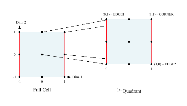
In this example, we will set up a FieldBundle for a 2D viscous and compressible flow problem. We will illustrate the FieldBundle halo update operation but we will not solve the non-linear PDEs here. The emphasis here is to demonstrate how to set up halo regions, how a numerical scheme updates the exclusive regions, and how halo update communicates data in the halo regions. Here are the governing equations:
![]() (conservation of momentum in x-direction)
(conservation of momentum in x-direction)
![]() (conservation of momentum in y-direction)
(conservation of momentum in y-direction)
![]() (conservation of mass)
(conservation of mass)
![]() (conservation of energy)
(conservation of energy)
The four unknowns are pressure ![]() , density
, density ![]() , velocity (
, velocity (![]() ,
, ![]() ). The grids
are set up using Arakawa D stagger (
). The grids
are set up using Arakawa D stagger (![]() on corner,
on corner, ![]() at center,
at center, ![]() and
and ![]() on edges).
on edges).
![]() ,
, ![]() ,
, ![]() , and
, and ![]() are bounded by necessary boundary conditions and initial conditions.
are bounded by necessary boundary conditions and initial conditions.
Section 22.2.14 provides a detailed discussion of the halo operation implemented in ESMF.
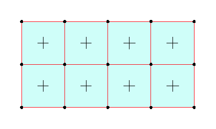
    ! create distgrid and grid according to the following decomposition
    ! and stagger pattern, r is density.
    !
    ! p--------u-------+p+-------u--------p
    ! !                 |                 |
    ! !                 |                 |
    ! !                 |                 |
    ! v        r        v        r        v
    ! !      PET 0      |      PET 1      |
    ! !                 |                 |
    ! !                 |                 |
    ! p--------u-------+p+-------u--------p
    ! !                 |                 |
    ! !                 |                 |
    ! !                 |                 |
    ! v        r        v        r        v
    ! !      PET 2      |      PET 3      |
    ! !                 |                 |
    ! !                 |                 |
    ! p--------u-------+p+-------u--------p
    !
    distgrid = ESMF_DistGridCreate(minIndex=(/1,1/), maxIndex=(/256,256/), &
        regDecomp=(/2,2/), &
        rc=rc)
    if(rc .ne. ESMF_SUCCESS) finalrc = ESMF_FAILURE

    grid = ESMF_GridCreate(distgrid=distgrid, name="grid", rc=rc)
    if(rc .ne. ESMF_SUCCESS) finalrc = ESMF_FAILURE

    call ESMF_ArraySpecSet(arrayspec, 2, ESMF_TYPEKIND_R4, rc=rc)
    if(rc .ne. ESMF_SUCCESS) finalrc = ESMF_FAILURE

    ! create field bundles and fields
    fieldBundle = ESMF_FieldBundleCreate(grid, rc=rc)
    if(rc .ne. ESMF_SUCCESS) finalrc = ESMF_FAILURE

    ! set up exclusive/total region for the fields
    !
    ! halo: L/U, nDim, nField, nPet
    ! halo configuration for pressure, and similarly for density, u, and v
    halo(1,1,1,1) = 0
    halo(2,1,1,1) = 0
    halo(1,2,1,1) = 0
    halo(2,2,1,1) = 0
    halo(1,1,1,2) = 1   ! halo in x direction on left hand side of pet 1
    halo(2,1,1,2) = 0
    halo(1,2,1,2) = 0
    halo(2,2,1,2) = 0
    halo(1,1,1,3) = 0
    halo(2,1,1,3) = 1   ! halo in y direction on upper side of pet 2
    halo(1,2,1,3) = 0
    halo(2,2,1,3) = 0
    halo(1,1,1,4) = 1   ! halo in x direction on left hand side of pet 3
    halo(2,1,1,4) = 1   ! halo in y direction on upper side of pet 3
    halo(1,2,1,4) = 0
    halo(2,2,1,4) = 0
    ! names and staggers of the 4 unknown fields
    names(1) = "pressure"
    names(2) = "density"
    names(3) = "u"
    names(4) = "v"
    staggers(1) = ESMF_STAGGERLOC_CORNER
    staggers(2) = ESMF_STAGGERLOC_CENTER
    staggers(3) = ESMF_STAGGERLOC_EDGE2
    staggers(4) = ESMF_STAGGERLOC_EDGE1

    ! create a FieldBundle
    lpe = lpe + 1
    do i = 1, 4
        field(i) = ESMF_FieldCreate(grid, arrayspec, &
                totalLWidth=(/halo(1,1,i,lpe), halo(1,2,i,lpe)/), &
                totalUWidth=(/halo(2,1,i,lpe), halo(2,2,i,lpe)/), &
                staggerloc=staggers(i), name=names(i), &
                rc=rc)
        if(rc .ne. ESMF_SUCCESS) finalrc = ESMF_FAILURE
        call ESMF_FieldBundleAdd(fieldBundle, field(i), rc=rc)
        if(rc .ne. ESMF_SUCCESS) finalrc = ESMF_FAILURE
    enddo

    ! compute the routehandle
    call ESMF_FieldBundleHaloStore(fieldBundle, routehandle=routehandle, &
                                   rc=rc)
    if(rc .ne. ESMF_SUCCESS) finalrc = ESMF_FAILURE

    do iter = 1, 10
        do i = 1, 4
            call ESMF_FieldGet(field(i), farrayPtr=fptr, &
                exclusiveLBound=excllb, exclusiveUBound=exclub, rc=rc)
            if(rc .ne. ESMF_SUCCESS) finalrc = ESMF_FAILURE
            sizes = exclub - excllb
            ! fill the total region with 0.
            fptr = 0.
            ! only update the exclusive region on local PET
            do j = excllb(1), exclub(1)
              do k = excllb(2), exclub(2)
                fptr(j,k) = iter * cos(2.*PI*j/sizes(1))*sin(2.*PI*k/sizes(2))
              enddo
            enddo
        enddo
        ! call halo execution to update the data in the halo region,
        ! it can be verified that the halo regions change from 0.
        ! to non zero values.
        call ESMF_FieldBundleHalo(fieldbundle, routehandle=routehandle, rc=rc)
        if(rc .ne. ESMF_SUCCESS) finalrc = ESMF_FAILURE
    enddo
    ! release halo route handle
    call ESMF_FieldBundleHaloRelease(routehandle, rc=rc)
    if(rc .ne. ESMF_SUCCESS) finalrc = ESMF_FAILURE
INTERFACE:
     interface assignment(=)
     fieldbundle1 = fieldbundle2
ARGUMENTS:
     type(ESMF_FieldBundle) :: fieldbundle1
     type(ESMF_FieldBundle) :: fieldbundle2
STATUS:
Backward compatible starting with ESMF 5.2r.
DESCRIPTION:
Assign fieldbundle1 as an alias to the same ESMF FieldBundle object in memory as fieldbundle2. If fieldbundle2 is invalid, then fieldbundle1 will be equally invalid after the assignment.
The arguments are:
INTERFACE:
   interface operator(==)
     if (fieldbundle1 == fieldbundle2) then ... endif
               OR
     result = (fieldbundle1 == fieldbundle2)
RETURN VALUE:
logical :: resultARGUMENTS:
     type(ESMF_FieldBundle), intent(in) :: fieldbundle1
     type(ESMF_FieldBundle), intent(in) :: fieldbundle2
STATUS:
Backward compatible starting with ESMF 5.2r.
DESCRIPTION:
Test whether fieldbundle1 and fieldbundle2 are valid aliases to the same ESMF FieldBundle object in memory. For a more general comparison of two ESMF FieldBundles, going beyond the simple alias test, the ESMF_FieldBundleMatch() function (not yet implemented) must be used.
The arguments are:
INTERFACE:
   interface operator(/=)
     if (fieldbundle1 == fieldbundle2) then ... endif
               OR
     result = (fieldbundle1 == fieldbundle2)
RETURN VALUE:
logical :: resultARGUMENTS:
     type(ESMF_FieldBundle), intent(in) :: fieldbundle1
     type(ESMF_FieldBundle), intent(in) :: fieldbundle2
STATUS:
Backward compatible starting with ESMF 5.2r.
DESCRIPTION:
Test whether fieldbundle1 and fieldbundle2 are not valid aliases to the same ESMF FieldBundle object in memory. For a more general comparison of two ESMF FieldBundles, going beyond the simple alias test, the ESMF_FieldBundleMatch() function (not yet implemented) must be used.
The arguments are:
INTERFACE:
       ! Private name; call using ESMF_FieldBundleAdd()
       subroutine ESMF_FieldBundleAddOneField(fieldbundle, field, &
         rc)
ARGUMENTS:
       type(ESMF_FieldBundle), intent(inout)         :: fieldbundle
       type(ESMF_Field),       intent(inout)         :: field
 -- The following arguments require argument keyword syntax (e.g. rc=rc). --
       integer,                intent(out), optional :: rc
STATUS:
Backward compatible starting with ESMF 5.2r.
DESCRIPTION:
Adds a single field to an existing fieldbundle. The field must be associated with the same geometry (i.e. ESMF_Grid, ESMF_Mesh, or ESMF_LocStream) as the other ESMF_Fields in the fieldbundle. The field is referenced by the fieldbundle, not copied.
The arguments are:
INTERFACE:
       ! Private name; call using ESMF_FieldBundleAdd()
       subroutine ESMF_FieldBundleAddFieldList(fieldbundle, fieldCount, &
           fieldList, rc)
ARGUMENTS:
       type(ESMF_FieldBundle),         intent(inout)         :: fieldbundle
       integer,                        intent(in)            :: fieldCount
       type(ESMF_Field), dimension(:), intent(inout)         :: fieldList
 -- The following arguments require argument keyword syntax (e.g. rc=rc). --
       integer,                        intent(out), optional :: rc
STATUS:
Backward compatible starting with ESMF 5.2r.
DESCRIPTION:
Adds a fieldList to an existing ESMF_FieldBundle. The items added from the fieldList must be associated with the same geometry (i.e. ESMF_Grid, ESMF_Mesh, or ESMF_LocStream) as the other ESMF_Fields in the fieldbundle. The items in the fieldList are referenced by the fieldbundle, not copied.
The arguments are:
INTERFACE:
       ! Private name; call using ESMF_FieldBundleCreate()
       function ESMF_FieldBundleCreateNew(fieldCount, fieldList, &
         packflag, name, rc)
RETURN VALUE:
type(ESMF_FieldBundle) :: ESMF_FieldBundleCreateNewARGUMENTS:
       integer,                        intent(in)            :: fieldCount
       type(ESMF_Field), dimension (:)                       :: fieldList
 -- The following arguments require argument keyword syntax (e.g. rc=rc). --
       type(ESMF_PackFlag),            intent(in),  optional :: packflag
       character (len = *),            intent(in),  optional :: name
       integer,                        intent(out), optional :: rc
STATUS:
Backward compatible starting with ESMF 5.2r.
DESCRIPTION:
Creates an ESMF_FieldBundle from a list of existing ESMF_Fields stored in a fieldList. All items in the fieldList must be associated with the same geometry (i.e. ESMF_Grid, ESMF_Mesh, or ESMF_LocStream). Returns a new ESMF_FieldBundle.
The arguments are:
INTERFACE:
       ! Private name; call using ESMF_FieldBundleCreate()
       function ESMF_FieldBundleCreateNFNone(name, rc)
RETURN VALUE:
type(ESMF_FieldBundle) :: ESMF_FieldBundleCreateNFNoneARGUMENTS:
 -- The following arguments require argument keyword syntax (e.g. rc=rc). --
       character (len = *), intent(in),  optional :: name
       integer,             intent(out), optional :: rc
STATUS:
Backward compatible starting with ESMF 5.2r.
DESCRIPTION:
Creates an ESMF_FieldBundle with no associated ESMF_Fields.
The arguments are:
INTERFACE:
       ! Private name; call using ESMF_FieldBundleCreate()
       function ESMF_FieldBundleCreateNFGrid(grid, name, rc)
RETURN VALUE:
type(ESMF_FieldBundle) :: ESMF_FieldBundleCreateNFGridARGUMENTS:
       type(ESMF_Grid),     intent(in)            :: grid
 -- The following arguments require argument keyword syntax (e.g. rc=rc). --
       character (len = *), intent(in),  optional :: name
       integer,             intent(out), optional :: rc
STATUS:
Backward compatible starting with ESMF 5.2r.
DESCRIPTION:
Creates an ESMF_FieldBundle with no associated ESMF_Fields.
The arguments are:
INTERFACE:
       ! Private name; call using ESMF_FieldBundleCreate()
       function ESMF_FieldBundleCreateNFMesh(mesh, name, rc)
RETURN VALUE:
type(ESMF_FieldBundle) :: ESMF_FieldBundleCreateNFMeshARGUMENTS:
       type(ESMF_Mesh),     intent(in)            :: mesh
 -- The following arguments require argument keyword syntax (e.g. rc=rc). --
       character (len = *), intent(in),  optional :: name
       integer,             intent(out), optional :: rc
STATUS:
Backward compatible starting with ESMF 5.2r.
DESCRIPTION:
Creates an ESMF_FieldBundle with no associated ESMF_Fields.
The arguments are:
INTERFACE:
       ! Private name; call using ESMF_FieldBundleCreate()
       function ESMF_FieldBundleCreateNFLS(locstream, name, rc)
RETURN VALUE:
type(ESMF_FieldBundle) :: ESMF_FieldBundleCreateNFLSARGUMENTS:
       type(ESMF_LocStream), intent(in)            :: locstream
 -- The following arguments require argument keyword syntax (e.g. rc=rc). --
       character (len = *),  intent(in),  optional :: name
       integer,              intent(out), optional :: rc
STATUS:
Backward compatible starting with ESMF 5.2r.
DESCRIPTION:
Creates an ESMF_FieldBundle with no associated ESMF_Fields.
The arguments are:
INTERFACE:
subroutine ESMF_FieldBundleDestroy(fieldbundle, rc)ARGUMENTS:
       type(ESMF_FieldBundle), intent(inout)          :: fieldbundle
 -- The following arguments require argument keyword syntax (e.g. rc=rc). --
       integer,                intent(out),  optional :: rc
STATUS:
Backward compatible starting with ESMF 5.2r.
DESCRIPTION:
Releases resources associated with the fieldbundle. This method does not destroy the ESMF_Fields that the fieldbundle contains. The fieldbundle should be destroyed before the ESMF_Fields within it are.
INTERFACE:
       ! Private name; call using ESMF_FieldBundleGet()
       subroutine ESMF_FieldBundleGetInfo(fieldbundle, &
         geomtype, grid, mesh, locstream, fieldNameList, fieldCount, name, rc)
ARGUMENTS:
       type(ESMF_FieldBundle), intent(in)            :: fieldbundle
 -- The following arguments require argument keyword syntax (e.g. rc=rc). --
       type(ESMF_GeomType),    intent(out), optional :: geomtype
       type(ESMF_Grid),        intent(out), optional :: grid
       type(ESMF_Mesh),        intent(out), optional :: mesh
       type(ESMF_LocStream),   intent(out), optional :: locstream
       character (len = *),    intent(out), optional :: fieldNameList(:)
       integer,                intent(out), optional :: fieldCount
       character (len = *),    intent(out), optional :: name
       integer,                intent(out), optional :: rc
STATUS:
Backward compatible starting with ESMF 5.2r.
DESCRIPTION:
Returns information about the fieldbundle. If the ESMF_FieldBundle was originally created without specifying a name, a unique name will have been generated by the framework.
The arguments are:
INTERFACE:
       ! Private name; call using ESMF_FieldBundleGet()
       subroutine ESMF_FieldBundleGetFieldByName(fieldbundle, fieldname, field, &
         rc)
ARGUMENTS:
       type(ESMF_FieldBundle), intent(in)            :: fieldbundle
       character (len = *),    intent(in)            :: fieldname
       type(ESMF_Field),       intent(out)           :: field
 -- The following arguments require argument keyword syntax (e.g. rc=rc). --
       integer,                intent(out), optional :: rc
STATUS:
Backward compatible starting with ESMF 5.2r.
DESCRIPTION:
Returns a field from a fieldbundle using the field's name.
The arguments are:
INTERFACE:
       ! Private name; call using ESMF_FieldBundleGet()
       subroutine ESMF_FieldBundleGetFieldByNum(fieldbundle, fieldIndex, &
         field, rc)
ARGUMENTS:
       type(ESMF_FieldBundle), intent(in)            :: fieldbundle
       integer,                intent(in)            :: fieldIndex
       type(ESMF_Field),       intent(out)           :: field
 -- The following arguments require argument keyword syntax (e.g. rc=rc). --
       integer,                intent(out), optional :: rc
STATUS:
Backward compatible starting with ESMF 5.2r.
DESCRIPTION:
Returns a field from a fieldbundle by index number.
The arguments are:
INTERFACE:
subroutine ESMF_FieldBundlePrint(fieldbundle, rc)ARGUMENTS:
       type(ESMF_FieldBundle), intent(in)            :: fieldbundle
 -- The following arguments require argument keyword syntax (e.g. rc=rc). --
       integer,                intent(out), optional :: rc
STATUS:
Backward compatible starting with ESMF 5.2r.
DESCRIPTION:
Prints diagnostic information about the fieldbundle
to stdout.
Note: Many ESMF_<class>Print methods are implemented in C++.
On some platforms/compilers there is a potential issue with interleaving
Fortran and C++ output to stdout such that it doesn't appear in
the expected order. If this occurs, the ESMF_IOUnitFlush() method
may be used on unit 6 to get coherent output.
The arguments are:
INTERFACE:
       subroutine ESMF_FieldBundleRead(fieldbundle, file, &
         singleFile, iofmt, rc)
ARGUMENTS:
       type(ESMF_FieldBundle), intent(inout)           :: fieldbundle
       character(*),           intent(in)              :: file
 -- The following arguments require argument keyword syntax (e.g. rc=rc). --
       logical,                intent(in),   optional  :: singleFile
       type(ESMF_IOFmtFlag),   intent(in),   optional  :: iofmt
       integer,                intent(out),  optional  :: rc
DESCRIPTION:
Read Field data to a FieldBundle object from file(s). For this API to be functional, the environment variable ESMF_PIO should be set to "internal" when the ESMF library is built. Please see the section on Data I/O, 30.3.
Limitations:
The arguments are:
INTERFACE:
subroutine ESMF_FieldBundleValidate(fieldbundle, rc)ARGUMENTS:
       type(ESMF_FieldBundle), intent(in)            :: fieldbundle
 -- The following arguments require argument keyword syntax (e.g. rc=rc). --
       integer,                intent(out), optional :: rc
STATUS:
Backward compatible starting with ESMF 5.2r.
DESCRIPTION:
Validates that the fieldbundle is internally consistent. Currently this method determines if the fieldbundle is uninitialized or already destroyed. The method returns an error code if problems are found.
The arguments are:
INTERFACE:
       subroutine ESMF_FieldBundleWrite(fieldbundle, file, &
         singleFile, timeslice, iofmt, rc)
ARGUMENTS:
       type(ESMF_FieldBundle), intent(inout)          :: fieldbundle
       character(*),           intent(in)             :: file
 -- The following arguments require argument keyword syntax (e.g. rc=rc). --
       logical,                intent(in),  optional  :: singleFile
       integer,                intent(in),  optional  :: timeslice
       type(ESMF_IOFmtFlag),   intent(in),  optional  :: iofmt
       integer,                intent(out), optional  :: rc
DESCRIPTION:
Write the Fields into a file. For this API to be functional, the environment variable ESMF_PIO should be set to "internal" when the ESMF library is built. Please see the section on Data I/O, 30.3.
Limitations:
The arguments are:
INTERFACE:
   subroutine ESMF_FieldBundleHalo(fieldbundle, routehandle, &
     checkflag, rc)
ARGUMENTS:
         type(ESMF_FieldBundle), intent(inout)           :: fieldbundle
         type(ESMF_RouteHandle), intent(inout)           :: routehandle
         type(ESMF_KeywordEnforcer),           optional  :: keywordEnforcer ! must use keywords below
         logical,                intent(in),   optional  :: checkflag
         integer,                intent(out),  optional  :: rc
STATUS:
Backward compatible starting with ESMF 5.2r.
DESCRIPTION:
Execute a precomputed FieldBundle halo operation for the Fields in fieldbundle. See ESMF_FieldBundleStore() on how to compute routehandle.
halo operation
INTERFACE:
subroutine ESMF_FieldBundleHaloRelease(routehandle, rc)ARGUMENTS:
         type(ESMF_RouteHandle), intent(inout)           :: routehandle
 -- The following arguments require argument keyword syntax (e.g. rc=rc). --
         integer,                intent(out),  optional  :: rc
STATUS:
Backward compatible starting with ESMF 5.2r.
DESCRIPTION:
Release resouces associated with a FieldBundle halo operation. After this call routehandle becomes invalid.
INTERFACE:
     subroutine ESMF_FieldBundleHaloStore(fieldbundle, routehandle, &
       rc)
ARGUMENTS:
     type(ESMF_FieldBundle), intent(inout)           :: fieldbundle
     type(ESMF_RouteHandle), intent(inout)           :: routehandle
 -- The following arguments require argument keyword syntax (e.g. rc=rc). --
     integer,                intent(out),   optional :: rc
STATUS:
Backward compatible starting with ESMF 5.2r.
DESCRIPTION:
Store a FieldBundle halo operation over the data in fieldbundle. By definition, all elements in the total Field regions that lie outside the exclusive regions will be considered potential destination elements for halo. However, only those elements that have a corresponding halo source element, i.e. an exclusive element on one of the DEs, will be updated under the halo operation. Elements that have no associated source remain unchanged under halo.
The routine returns an ESMF_RouteHandle that can be used to call ESMF_FieldBundleHalo() on any FieldBundle that is weakly congruent and typekind conform to fieldbundle. Congruency for FieldBundles is given by the congruency of its constituents. Congruent Fields possess matching DistGrids, and the shape of the local array tiles matches between the Fields for every DE. For weakly congruent Fields the sizes of the undistributed dimensions, that vary faster with memory than the first distributed dimension, are permitted to be different. This means that the same routehandle can be applied to a large class of similar Fields that differ in the number of elements in the left most undistributed dimensions.
This call is collective across the current VM.
INTERFACE:
   subroutine ESMF_FieldBundleRedist(srcFieldBundle, dstFieldBundle, &
     routehandle, checkflag, rc)
ARGUMENTS:
         type(ESMF_FieldBundle), intent(in),    optional  :: srcFieldBundle
         type(ESMF_FieldBundle), intent(inout), optional  :: dstFieldBundle
         type(ESMF_RouteHandle), intent(inout)            :: routehandle
 -- The following arguments require argument keyword syntax (e.g. rc=rc). --
         logical,                intent(in),    optional  :: checkflag
         integer,                intent(out),   optional  :: rc
STATUS:
Backward compatible starting with ESMF 5.2r.
DESCRIPTION:
Execute a precomputed FieldBundle redistribution from srcFieldBundle to dstFieldBundle. Both srcFieldBundle and dstFieldBundle must be weakly congruent and typekind conform with the respective FieldBundles used during ESMF_FieldBundleRedistStore(). Congruent FieldBundles possess matching DistGrids and the shape of the local array tiles matches between the FieldBundles for every DE. For weakly congruent Fields the sizes of the undistributed dimensions, that vary faster with memory than the first distributed dimension, are permitted to be different. This means that the same routehandle can be applied to a large class of similar Fields that differ in the number of elements in the left most undistributed dimensions.
It is erroneous to specify the identical FieldBundle object for srcFieldBundle and dstFieldBundle arguments.
See ESMF_FieldBundleRedistStore() on how to precompute routehandle.
This call is collective across the current VM.
For examples and associated documentations using this method see Section 19.3.4.
redistribution
INTERFACE:
subroutine ESMF_FieldBundleRedistRelease(routehandle, rc)ARGUMENTS:
         type(ESMF_RouteHandle), intent(inout)           :: routehandle
 -- The following arguments require argument keyword syntax (e.g. rc=rc). --
         integer,                intent(out),  optional  :: rc
STATUS:
Backward compatible starting with ESMF 5.2r.
DESCRIPTION:
Release resouces associated with a FieldBundle redistribution. After this call routehandle becomes invalid.
with local factor argument
INTERFACE:
   ! Private name; call using ESMF_FieldBundleRedistStore()
   subroutine ESMF_FieldBundleRedistStore<type><kind>(srcFieldBundle, &
     dstFieldBundle, & routehandle, factor, &
     srcToDstTransposeMap, rc)
ARGUMENTS:
     type(ESMF_FieldBundle),   intent(in)             :: srcFieldBundle
     type(ESMF_FieldBundle),   intent(inout)          :: dstFieldBundle
     type(ESMF_RouteHandle),   intent(inout)          :: routehandle
     <type>(ESMF_KIND_<kind>), intent(in)             :: factor
 -- The following arguments require argument keyword syntax (e.g. rc=rc). --
     integer,                  intent(in),   optional :: srcToDstTransposeMap(:)
     integer,                  intent(out),  optional :: rc
STATUS:
Backward compatible starting with ESMF 5.2r.
DESCRIPTION:
Store a FieldBundle redistribution operation from srcFieldBundle to dstFieldBundle. PETs that specify a factor argument must use the <type><kind> overloaded interface. Other PETs call into the interface without factor argument. If multiple PETs specify the factor argument its type and kind as well as its value must match across all PETs. If none of the PETs specifies a factor argument the default will be a factor of 1.
Both srcFieldBundle and dstFieldBundle are interpreted as sequentialized vectors. The sequence is defined by the order of DistGrid dimensions and the order of tiles within the DistGrid or by user-supplied arbitrary sequence indices. See section 22.2.17 for details on the definition of sequence indices. Redistribution corresponds to an identity mapping of the source FieldBundle vector to the destination FieldBundle vector.
Source and destination FieldBundles may be of different <type><kind>. Further source and destination FieldBundles may differ in shape, however, the number of elements must match.
It is erroneous to specify the identical FieldBundle object for srcFieldBundle and dstFieldBundle arguments.
The routine returns an ESMF_RouteHandle that can be used to call ESMF_FieldBundleRedist() on any pair of FieldBundles that are congruent and typekind conform with the srcFieldBundle, dstFieldBundle pair. Congruent FieldBundles possess matching DistGrids and the shape of the local array tiles matches between the FieldBundles for every DE. For weakly congruent Fields the sizes of the undistributed dimensions, that vary faster with memory than the first distributed dimension, are permitted to be different. This means that the same routehandle can be applied to a large class of similar Fields that differ in the number of elements in the left most undistributed dimensions.
This method is overloaded for:
ESMF_TYPEKIND_I4, ESMF_TYPEKIND_I8,
ESMF_TYPEKIND_R4, ESMF_TYPEKIND_R8.
This call is collective across the current VM.
For examples and associated documentations using this method see Section 19.3.4.
The arguments are:
INTERFACE:
   ! Private name; call using ESMF_FieldBundleRedistStore()
   subroutine ESMF_FieldBundleRedistStoreNF(srcFieldBundle, dstFieldBundle, &
          routehandle, factor, srcToDstTransposeMap, rc)
ARGUMENTS:
     type(ESMF_FieldBundle),  intent(in)             :: srcFieldBundle
     type(ESMF_FieldBundle),  intent(inout)          :: dstFieldBundle
     type(ESMF_RouteHandle),  intent(inout)          :: routehandle
 -- The following arguments require argument keyword syntax (e.g. rc=rc). --
     integer,                 intent(in),   optional :: srcToDstTransposeMap(:)
     integer,                 intent(out),  optional :: rc
STATUS:
Backward compatible starting with ESMF 5.2r.
DESCRIPTION:
Store a FieldBundle redistribution operation from srcFieldBundle to dstFieldBundle. PETs that specify non-zero matrix coefficients must use the <type><kind> overloaded interface and provide the factorList and factorIndexList arguments. Providing factorList and factorIndexList arguments with size(factorList) = (/0/) and size(factorIndexList) = (/2,0/) or (/4,0/) indicates that a PET does not provide matrix elements. Alternatively, PETs that do not provide matrix elements may also call into the overloaded interface without factorList and factorIndexList arguments.
Both srcFieldBundle and dstFieldBundle are interpreted as sequentialized vectors. The sequence is defined by the order of DistGrid dimensions and the order of tiles within the DistGrid or by user-supplied arbitrary sequence indices. See section 22.2.17 for details on the definition of sequence indices. Redistribution corresponds to an identity mapping of the source FieldBundle vector to the destination FieldBundle vector.
Source and destination Fields may be of different <type><kind>. Further source and destination Fields may differ in shape, however, the number of elements must match.
It is erroneous to specify the identical FieldBundle object for srcFieldBundle and dstFieldBundle arguments.
The routine returns an ESMF_RouteHandle that can be used to call ESMF_FieldBundleRedist() on any pair of Fields that are congruent and typekind conform with the srcFieldBundle, dstFieldBundle pair. Congruent Fields possess matching DistGrids and the shape of the local array tiles matches between the Fields for every DE. For weakly congruent Fields the sizes of the undistributed dimensions, that vary faster with memory than the first distributed dimension, are permitted to be different. This means that the same routehandle can be applied to a large class of similar Fields that differ in the number of elements in the left most undistributed dimensions.
This method is overloaded for:
ESMF_TYPEKIND_I4, ESMF_TYPEKIND_I8,
ESMF_TYPEKIND_R4, ESMF_TYPEKIND_R8.
This call is collective across the current VM.
For examples and associated documentations using this method see Section 19.3.4.
The arguments are:
INTERFACE:
   subroutine ESMF_FieldBundleRegrid(srcFieldBundle, dstFieldBundle, &
          routehandle, zeroflag, checkflag, rc)
ARGUMENTS:
         type(ESMF_FieldBundle), intent(in),    optional  :: srcFieldBundle
         type(ESMF_FieldBundle), intent(inout), optional  :: dstFieldBundle
         type(ESMF_RouteHandle), intent(inout)            :: routehandle
 -- The following arguments require argument keyword syntax (e.g. rc=rc). --
         type(ESMF_RegionFlag),  intent(in),    optional  :: zeroflag
         logical,                intent(in),    optional  :: checkflag
         integer,                intent(out),   optional  :: rc
STATUS:
Backward compatible starting with ESMF 5.2r.
DESCRIPTION:
Execute a precomputed FieldBundle regrid from srcFieldBundle to dstFieldBundle. Both srcFieldBundle and dstFieldBundle must be congruent and typekind conform with the respective FieldBundles used during ESMF_FieldBundleRegridStore(). Congruent FieldBundles possess matching DistGrids and the shape of the local array tiles matches between the FieldBundles for every DE. For weakly congruent Fields the sizes of the undistributed dimensions, that vary faster with memory than the first distributed dimension, are permitted to be different. This means that the same routehandle can be applied to a large class of similar Fields that differ in the number of elements in the left most undistributed dimensions.
It is erroneous to specify the identical FieldBundle object for srcFieldBundle and dstFieldBundle arguments.
See ESMF_FieldBundleRegridStore() on how to precompute routehandle.
This call is collective across the current VM.
INTERFACE:
subroutine ESMF_FieldBundleRegridRelease(routehandle, rc)ARGUMENTS:
         type(ESMF_RouteHandle), intent(inout)           :: routehandle
 -- The following arguments require argument keyword syntax (e.g. rc=rc). --
         integer,                intent(out),  optional  :: rc
STATUS:
Backward compatible starting with ESMF 5.2r.
DESCRIPTION:
Release resouces associated with a FieldBundle regrid operation. After this call routehandle becomes invalid.
INTERFACE:
     subroutine ESMF_FieldBundleRegridStore(srcFieldBundle, dstFieldBundle, &
                                            &
                                            srcMaskValues, dstMaskValues, &
                                            regridMethod, regridPoleType, &
                                            regridPoleNPnts, regridScheme, &
                                            unmappedDstAction, routehandle, rc)
ARGUMENTS:
     type(ESMF_FieldBundle),    intent(inout)           :: srcFieldBundle
     type(ESMF_FieldBundle),    intent(inout)           :: dstFieldBundle
 -- The following arguments require argument keyword syntax (e.g. rc=rc). --
     integer(ESMF_KIND_I4),     intent(in),    optional :: srcMaskValues(:)
     integer(ESMF_KIND_I4),     intent(in),    optional :: dstMaskValues(:)
     type(ESMF_RegridMethod),   intent(in),    optional :: regridMethod
     type(ESMF_RegridPole),     intent(in),    optional :: regridPoleType
     integer,                   intent(in),    optional :: regridPoleNPnts
     integer,                   intent(in),    optional :: regridScheme
     type(ESMF_UnmappedAction), intent(in),    optional :: unmappedDstAction
     type(ESMF_RouteHandle),    intent(inout), optional :: routehandle
     integer,                   intent(out),   optional :: rc
DESCRIPTION:
Store a FieldBundle regrid operation over the data in srcFieldBundle and dstFieldBundle pair.
The routine returns an ESMF_RouteHandle that can be used to call ESMF_FieldBundleRegrid() on any FieldBundle pairs that are weakly congruent and typekind conform to the FieldBundle pair used here. Congruency for FieldBundles is given by the congruency of its constituents. Congruent Fields possess matching DistGrids, and the shape of the local array tiles matches between the Fields for every DE. For weakly congruent Fields the sizes of the undistributed dimensions, that vary faster with memory than the first distributed dimension, are permitted to be different. This means that the same routehandle can be applied to a large class of similar Fields that differ in the number of elements in the left most undistributed dimensions. Note ESMF_FieldBundleRegridStore() assumes the coordinates used in the Grids upon which the FieldBundles are built are in degrees.
This call is collective across the current VM.
INTERFACE:
   subroutine ESMF_FieldBundleSMM(srcFieldBundle, dstFieldBundle, &
         routehandle, zeroflag, checkflag, rc)
ARGUMENTS:
         type(ESMF_FieldBundle), intent(in),    optional  :: srcFieldBundle
         type(ESMF_FieldBundle), intent(inout), optional  :: dstFieldBundle
         type(ESMF_RouteHandle), intent(inout)            :: routehandle
 -- The following arguments require argument keyword syntax (e.g. rc=rc). --
         type(ESMF_RegionFlag),  intent(in),    optional  :: zeroflag
         logical,                intent(in),    optional  :: checkflag
         integer,                intent(out),   optional  :: rc
STATUS:
Backward compatible starting with ESMF 5.2r.
DESCRIPTION:
Execute a precomputed FieldBundle sparse matrix multiplication from srcFieldBundle to dstFieldBundle. Both srcFieldBundle and dstFieldBundle must be congruent and typekind conform with the respective FieldBundles used during ESMF_FieldBundleSMMStore(). Congruent FieldBundles possess matching DistGrids and the shape of the local array tiles matches between the FieldBundles for every DE. For weakly congruent Fields the sizes of the undistributed dimensions, that vary faster with memory than the first distributed dimension, are permitted to be different. This means that the same routehandle can be applied to a large class of similar Fields that differ in the number of elements in the left most undistributed dimensions.
It is erroneous to specify the identical FieldBundle object for srcFieldBundle and dstFieldBundle arguments.
See ESMF_FieldBundleSMMStore() on how to precompute routehandle.
This call is collective across the current VM.
For examples and associated documentations using this method see Section 19.3.5.
ESMF_REGION_SELECT will only zero out those elements in the destination FieldBundle that will be updated by the sparse matrix multiplication. See section 9.2.14 for a complete list of valid settings.
sparse matrix multiplication
INTERFACE:
subroutine ESMF_FieldBundleSMMRelease(routehandle, rc)ARGUMENTS:
         type(ESMF_RouteHandle), intent(inout)           :: routehandle
 -- The following arguments require argument keyword syntax (e.g. rc=rc). --
         integer,                intent(out),  optional  :: rc
STATUS:
Backward compatible starting with ESMF 5.2r.
DESCRIPTION:
Release resouces associated with a FieldBundle sparse matrix multiplication. After this call routehandle becomes invalid.
INTERFACE:
   ! Private name; call using ESMF_FieldBundleSMMStore()
   subroutine ESMF_FieldBundleSMMStore<type><kind>(srcFieldBundle, &
     dstFieldBundle,  routehandle, factorList, factorIndexList, &
     rc)
ARGUMENTS:
     type(ESMF_FieldBundle),   intent(in)            :: srcFieldBundle
     type(ESMF_FieldBundle),   intent(inout)         :: dstFieldBundle
     type(ESMF_RouteHandle),   intent(inout)         :: routehandle
     <type>(ESMF_KIND_<kind>), intent(in)            :: factorList(:)
     integer,                  intent(in),           :: factorIndexList(:,:)
 -- The following arguments require argument keyword syntax (e.g. rc=rc). --
     integer,                  intent(out), optional :: rc
STATUS:
Backward compatible starting with ESMF 5.2r.
DESCRIPTION:
Store a FieldBundle sparse matrix multiplication operation from srcFieldBundle to dstFieldBundle. PETs that specify non-zero matrix coefficients must use the <type><kind> overloaded interface and provide the factorList and factorIndexList arguments. Providing factorList and factorIndexList arguments with size(factorList) = (/0/) and size(factorIndexList) = (/2,0/) or (/4,0/) indicates that a PET does not provide matrix elements. Alternatively, PETs that do not provide matrix elements may also call into the overloaded interface without factorList and factorIndexList arguments.
Both srcFieldBundle and dstFieldBundle are interpreted as sequentialized vectors. The sequence is defined by the order of DistGrid dimensions and the order of tiles within the DistGrid or by user-supplied arbitrary sequence indices. See section 22.2.17 for details on the definition of sequence indices. SMM corresponds to an identity mapping of the source FieldBundle vector to the destination FieldBundle vector.
Source and destination Fields may be of different <type><kind>. Further source and destination Fields may differ in shape, however, the number of elements must match.
It is erroneous to specify the identical FieldBundle object for srcFieldBundle and dstFieldBundle arguments.
The routine returns an ESMF_RouteHandle that can be used to call ESMF_FieldBundleSMM() on any pair of FieldBundles that are congruent and typekind conform with the srcFieldBundle, dstFieldBundle pair. Congruent FieldBundles possess matching DistGrids and the shape of the local array tiles matches between the FieldBundles for every DE. For weakly congruent Fields the sizes of the undistributed dimensions, that vary faster with memory than the first distributed dimension, are permitted to be different. This means that the same routehandle can be applied to a large class of similar Fields that differ in the number of elements in the left most undistributed dimensions.
This method is overloaded for:
ESMF_TYPEKIND_I4, ESMF_TYPEKIND_I8,
ESMF_TYPEKIND_R4, ESMF_TYPEKIND_R8.
This call is collective across the current VM.
For examples and associated documentations using this method see Section 19.3.5.
The arguments are:
The second dimension of factorIndexList steps through the list of pairs, i.e. size(factorIndexList,2) == size(factorList). The first dimension of factorIndexList is either of size 2 or size 4.
In the size 2 format factorIndexList(1,:) specifies the sequence index of the source element in the srcFieldBundle while factorIndexList(2,:) specifies the sequence index of the destination element in dstFieldBundle. For this format to be a valid option source and destination FieldBundles must have matching number of tensor elements (the product of the sizes of all Field tensor dimensions). Under this condition an identiy matrix can be applied within the space of tensor elements for each sparse matrix factor.
The size 4 format is more general and does not require a matching tensor element count. Here the
factorIndexList(1,:) specifies the sequence index while factorIndexList(2,:) specifies the tensor sequence index of the source element in the srcFieldBundle. Further factorIndexList(3,:) specifies the sequence index and factorIndexList(4,:) specifies the tensor sequence index of the destination element in the dstFieldBundle.
See section 22.2.17 for details on the definition of sequence indices and tensor sequence indices.
INTERFACE:
   ! Private name; call using ESMF_FieldBundleSMMStore()
   subroutine ESMF_FieldBundleSMMStoreNF(srcFieldBundle, dstFieldBundle, &
          routehandle, rc)
ARGUMENTS:
     type(ESMF_FieldBundle),   intent(in)            :: srcFieldBundle
     type(ESMF_FieldBundle),   intent(inout)         :: dstFieldBundle
     type(ESMF_RouteHandle),   intent(inout)         :: routehandle
 -- The following arguments require argument keyword syntax (e.g. rc=rc). --
     integer,                  intent(out), optional :: rc
STATUS:
Backward compatible starting with ESMF 5.2r.
DESCRIPTION:
Store a FieldBundle sparse matrix multiplication operation from srcFieldBundle to dstFieldBundle. PETs that specify non-zero matrix coefficients must use the <type><kind> overloaded interface and provide the factorList and factorIndexList arguments. Providing factorList and factorIndexList arguments with size(factorList) = (/0/) and size(factorIndexList) = (/2,0/) or (/4,0/) indicates that a PET does not provide matrix elements. Alternatively, PETs that do not provide matrix elements may also call into the overloaded interface without factorList and factorIndexList arguments.
Both srcFieldBundle and dstFieldBundle are interpreted as sequentialized vectors. The sequence is defined by the order of DistGrid dimensions and the order of tiles within the DistGrid or by user-supplied arbitrary sequence indices. See section 22.2.17 for details on the definition of sequence indices. SMM corresponds to an identity mapping of the source FieldBundle vector to the destination FieldBundle vector.
Source and destination Fields may be of different <type><kind>. Further source and destination Fields may differ in shape, however, the number of elements must match.
It is erroneous to specify the identical FieldBundle object for srcFieldBundle and dstFieldBundle arguments.
The routine returns an ESMF_RouteHandle that can be used to call ESMF_FieldBundleSMM() on any pair of FieldBundles that are congruent and typekind conform with the srcFieldBundle, dstFieldBundle pair. Congruent FieldBundles possess matching DistGrids and the shape of the local array tiles matches between the FieldBundles for every DE. For weakly congruent Fields the sizes of the undistributed dimensions, that vary faster with memory than the first distributed dimension, are permitted to be different. This means that the same routehandle can be applied to a large class of similar Fields that differ in the number of elements in the left most undistributed dimensions.
This method is overloaded for ESMF_TYPEKIND_I4, ESMF_TYPEKIND_I8, ESMF_TYPEKIND_R4, ESMF_TYPEKIND_R8.
This call is collective across the current VM.
For examples and associated documentations using this method see Section 19.3.5.
The arguments are:
An ESMF Field represents a physical field, such as temperature. The motivation for including Fields in ESMF is that bundles of Fields are the entities that are normally exchanged when coupling Components.
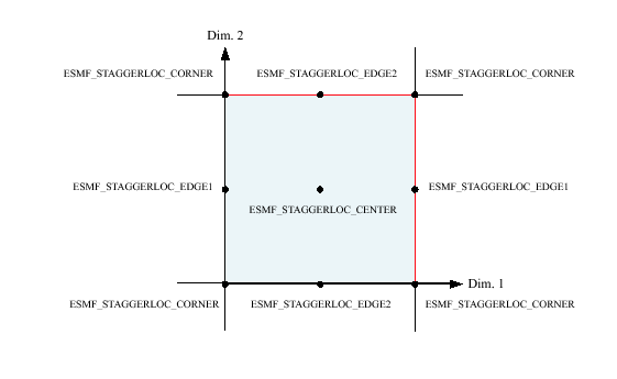
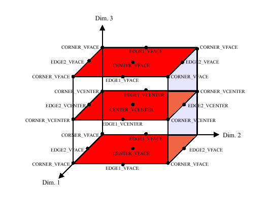
The ESMF Field class contains distributed and discretized field data, a reference to its associated grid, and metadata. The Field class stores the grid staggering for that physical field. This is the relationship of how the data array of a field maps onto a grid (e.g. one item per cell located at the cell center, one item per cell located at the NW corner, one item per cell vertex, etc.). This means that different Fields which are on the same underlying ESMF Grid but have different staggerings can share the same Grid object without needing to replicate it multiple times.
Fields can be added to States for use in inter-Component data communications. Fields can also be added to FieldBundles, which are groups of Fields on the same underlying Grid. One motivation for packing Fields into FieldBundles is convenience; another is the ability to perform optimized collective data transfers.
Field communication capabilities include: data redistribution, regridding, scatter, gather, sparse-matrix multiplication, and halo update. These are discussed in more detail in the documentation for the specific method calls. ESMF does not currently support vector fields, so the components of a vector field must be stored as separate Field objects.
Valid values are:
Valid values are:
A Field serves as an annotator of data, since it carries a description of the grid it is associated with and metadata such as name and units. Fields can be used in this capacity alone, as convenient, descriptive containers into which arrays can be placed and retrieved. However, for most codes the primary use of Fields is in the context of import and export States, which are the objects that carry coupling information between Components. Fields enable data to be self-describing, and a State holding ESMF Fields contains data in a standard format that can be queried and manipulated.
The sections below go into more detail about Field usage.
Fields can be created and destroyed at any time during application execution. However, these Field methods require some time to complete. We do not recommend that the user create or destroy Fields inside performance-critical computational loops.
All versions of the ESMF_FieldCreate() routines require a Grid object as input, or require a Grid be added before most operations involving Fields can be performed. The Grid contains the information needed to know which Decomposition Elements (DEs) are participating in the processing of this Field, and which subsets of the data are local to a particular DE.
The details of how the create process happens depends on which of the variants of the ESMF_FieldCreate() call is used. Some of the variants are discussed below.
There are versions of the ESMF_FieldCreate() interface which create the Field based on the input Grid. The ESMF can allocate the proper amount of space but not assign initial values. The user code can then get the pointer to the uninitialized buffer and set the initial data values.
Other versions of the ESMF_FieldCreate() interface allow user code to attach arrays that have already been allocated by the user. Empty Fields can also be created in which case the data can be added at some later time.
For versions of Create which do not specify data values, user code can create an ArraySpec object, which contains information about the typekind and rank of the data values in the array. Then at Field create time, the appropriate amount of memory is allocated to contain the data which is local to each DE.
When finished with a ESMF_Field, the ESMF_FieldDestroy method removes it. However, the objects inside the ESMF_Field created externally should be destroyed separately, since objects can be added to more than one ESMF_Field. For example, the same ESMF_Grid can be referenced by multiple ESMF_Fields. In this case the internal Grid is not deleted by the ESMF_FieldDestroy call.
A user can get bounds and counts information from an ESMF_Field through the ESMF_FieldGet() interface. Also available through this interface is the intrinsic Fortran data pointer contained in the internal ESMF_Array object of an ESMF_Field. The bounds and counts information are DE specific for the associated Fortran data pointer.
For a better discussion of the terminologies, bounds and widths in ESMF e.g. exclusive, computational, total bounds for the lower and upper corner of data region, etc.., user can refer to the explanation of these concepts for Grid and Array in their respective sections in the Reference Manual, e.g. Section 22.2.6 on Array and Section 25.3.15 on Grid.
In this example, we first create a 3D Field based on a 3D Grid and Array. Then we use the ESMF_FieldGet() interface to retrieve the data pointer, potentially updating or verifying its values. We also retrieve the bounds and counts information of the 3D Field to assist in data element iteration.
    xdim = 180
    ydim = 90
    zdim = 50

    ! create a 3D data Field from a Grid and Array.
    ! first create a Grid
    grid3d = ESMF_GridCreateShapeTile(minIndex=(/1,1,1/), &
            maxIndex=(/xdim,ydim,zdim/), &
            regDecomp=(/2,2,1/), name="grid", rc=rc)
    if(rc .ne. ESMF_SUCCESS) finalrc = ESMF_FAILURE

    call ESMF_GridGet(grid=grid3d, staggerloc=ESMF_STAGGERLOC_CENTER, &
           distgrid=distgrid3d, rc=rc)
    if(rc .ne. ESMF_SUCCESS) finalrc = ESMF_FAILURE

    call ESMF_FieldGet(grid=grid3d, localDe=0, &
        staggerloc=ESMF_STAGGERLOC_CENTER, totalCount=fa_shape, rc=rc)
    if(rc .ne. ESMF_SUCCESS) finalrc = ESMF_FAILURE

    allocate(farray(fa_shape(1), fa_shape(2), fa_shape(3)) )

    ! create an Array
    array3d = ESMF_ArrayCreate(farray, distgrid=distgrid3d, &
	indexflag=ESMF_INDEX_DELOCAL, rc=rc)
    if(rc .ne. ESMF_SUCCESS) finalrc = ESMF_FAILURE

    ! create a Field
    field = ESMF_FieldCreate(grid=grid3d, array=array3d, rc=rc)
    if(rc .ne. ESMF_SUCCESS) finalrc = ESMF_FAILURE

    ! retrieve the Fortran data pointer from the Field
    call ESMF_FieldGet(field=field, localDe=0, farrayPtr=farray1, rc=rc)
    if(rc .ne. ESMF_SUCCESS) finalrc = ESMF_FAILURE

    ! retrieve the Fortran data pointer from the Field and bounds
    call ESMF_FieldGet(field=field, localDe=0, farrayPtr=farray1, &
        computationalLBound=compLBnd, computationalUBound=compUBnd, &
        exclusiveLBound=exclLBnd, exclusiveUBound=exclUBnd, &
        totalLBound=totalLBnd, totalUBound=totalUBnd, &
        computationalCount=comp_count, &
        exclusiveCount=excl_count, &
        totalCount=total_count, &
        rc=rc)

    ! iterate through the total bounds of the field data pointer
    do k = totalLBnd(3), totalUBnd(3)
        do j = totalLBnd(2), totalUBnd(2)
            do i = totalLBnd(1), totalUBnd(1)
                farray1(i, j, k) = sin(2*i/total_count(1)*PI) + &
                    sin(4*j/total_count(2)*PI) + &
                    sin(8*k/total_count(2)*PI)
            enddo
        enddo
    enddo
A user can get the internal ESMF_Grid and ESMF_Array from a ESMF_Field. Note that the user should not issue any destroy command on the retrieved grid or array object since they are referenced from within the ESMF_Field. The retrieved objects should be used in a read-only fashion to query additional information not directly available through the ESMF_FieldGet() interface.
    call ESMF_FieldGet(field, grid=grid, array=array, &
        typekind=typekind, dimCount=dimCount, staggerloc=staggerloc, &
        gridToFieldMap=gridToFieldMap, &
        ungriddedLBound=ungriddedLBound, ungriddedUBound=ungriddedUBound, &
        totalLWidth=totalLWidth, totalUWidth=totalUWidth, &
        name=name, &
        rc=rc)
A user can create an ESMF_Field from an ESMF_Grid and typekind/rank. This create method associates the two objects.
We first create a Grid with a regular distribution that is 10x20 index in 2x2 DEs. This version of Field create simply associates the data with the Grid. The data is referenced explicitly on a regular 2x2 uniform grid. Finally we create a Field from the Grid, typekind, rank, and a user specified StaggerLoc.
This example also illustrates a typical use of this Field creation method. By creating a Field from a Grid and typekind/rank, the user allows the ESMF library to create a internal Array in the Field. Then the user can use ESMF_FieldGet() to retrieve the Fortran data array and necessary bounds information to assign initial values to it.
    ! create a grid
    grid = ESMF_GridCreateShapeTile(minIndex=(/1,1/), maxIndex=(/10,20/), &
          regDecomp=(/2,2/), name="atmgrid", rc=rc)
    if (rc.NE.ESMF_SUCCESS) finalrc = ESMF_FAILURE

    ! create a Field from the Grid and arrayspec
    field1 = ESMF_FieldCreate(grid, typekind=ESMF_TYPEKIND_R4, &
        indexflag=ESMF_INDEX_DELOCAL, &
        staggerloc=ESMF_STAGGERLOC_CENTER, name="pressure", rc=rc)
    if (rc.NE.ESMF_SUCCESS) finalrc = ESMF_FAILURE

    call ESMF_FieldGet(field1, localDe=0, farrayPtr=farray2dd, &
        totalLBound=ftlb, totalUBound=ftub, totalCount=ftc, rc=rc)

    do i = ftlb(1), ftub(1)
        do j = ftlb(2), ftub(2)
            farray2dd(i, j) = sin(i/ftc(1)*PI) * cos(j/ftc(2)*PI)
        enddo
    enddo

    if (rc.NE.ESMF_SUCCESS) finalrc = ESMF_FAILURE
A user can create an ESMF_Field from an ESMF_Grid and a ESMF_Arrayspec with corresponding rank and type. This create method associates the two objects.
We first create a Grid with a regular distribution that is 10x20 index in 2x2 DEs. This version of Field create simply associates the data with the Grid. The data is referenced explicitly on a regular 2x2 uniform grid. Then we create an ArraySpec. Finally we create a Field from the Grid, ArraySpec, and a user specified StaggerLoc.
This example also illustrates a typical use of this Field creation method. By creating a Field from a Grid and an ArraySpec, the user allows the ESMF library to create a internal Array in the Field. Then the user can use ESMF_FieldGet() to retrieve the Fortran data array and necessary bounds information to assign initial values to it.
    ! create a grid
    grid = ESMF_GridCreateShapeTile(minIndex=(/1,1/), maxIndex=(/10,20/), &
          regDecomp=(/2,2/), name="atmgrid", rc=rc)
    if (rc.NE.ESMF_SUCCESS) finalrc = ESMF_FAILURE

    ! setup arrayspec
    call ESMF_ArraySpecSet(arrayspec, 2, ESMF_TYPEKIND_R4, rc=rc)
    if (rc.NE.ESMF_SUCCESS) finalrc = ESMF_FAILURE

    ! create a Field from the Grid and arrayspec
    field1 = ESMF_FieldCreate(grid, arrayspec, indexflag=ESMF_INDEX_DELOCAL, &
         staggerloc=ESMF_STAGGERLOC_CENTER, name="pressure", rc=rc)
    if (rc.NE.ESMF_SUCCESS) finalrc = ESMF_FAILURE

    call ESMF_FieldGet(field1, localDe=0, farrayPtr=farray2dd, &
        totalLBound=ftlb, totalUBound=ftub, totalCount=ftc, rc=rc)

    do i = ftlb(1), ftub(1)
        do j = ftlb(2), ftub(2)
            farray2dd(i, j) = sin(i/ftc(1)*PI) * cos(j/ftc(2)*PI)
        enddo
    enddo

    if (rc.NE.ESMF_SUCCESS) finalrc = ESMF_FAILURE
A user can also create an ArraySpec that has a different rank from the Grid, For example, the following code shows creation of of 3D Field from a 2D Grid using a 3D ArraySpec.
This example also demonstrates the technique to create a typical 3D data Field that has 2 gridded dimensions and 1 ungridded dimension.
First we create a 2D grid with an index space of 180x360 equivalent to 180x360 Grid cells (note that for a distributed memory computer, this means each grid cell will be on a separate PE!). In the FieldCreate call, we use gridToFieldMap to indicate the mapping between Grid dimension and Field dimension. For the ungridded dimension (typically the altitude), we use ungriddedLBound and ungriddedUBound to describe its bounds. Internally the ungridded dimension has a stride of 1, so the number of elements of the ungridded dimension is ungriddedUBound - ungriddedLBound + 1.
Note that gridToFieldMap in this specific example is (/1,2/) which is the default value so the user can neglect this argument for the FieldCreate call.
    grid2d = ESMF_GridCreateShapeTile(minIndex=(/1,1/), &
          maxIndex=(/180,360/), regDecomp=(/2,2/), name="atmgrid", rc=rc)
    if (rc.NE.ESMF_SUCCESS) finalrc = ESMF_FAILURE

    call ESMF_ArraySpecSet(arrayspec, 3, ESMF_TYPEKIND_R4, rc=rc)
    if (rc.NE.ESMF_SUCCESS) finalrc = ESMF_FAILURE

    field1 = ESMF_FieldCreate(grid2d, arrayspec, indexflag=ESMF_INDEX_DELOCAL, &
         staggerloc=ESMF_STAGGERLOC_CENTER, &
         gridToFieldMap=(/1,2/), &
         ungriddedLBound=(/1/), ungriddedUBound=(/50/), &
         name="pressure", rc=rc)
    if (rc.NE.ESMF_SUCCESS) finalrc = ESMF_FAILURE
A user can create an ESMF_Field from an ESMF_Grid and a ESMF_Array. The Grid was created in the previous example.
This example creates a 2D ESMF_Field from a 2D ESMF_Grid and a 2D ESMF_Array.
    ! Get necessary information from the Grid
    call ESMF_GridGet(grid, staggerloc=ESMF_STAGGERLOC_CENTER, &
        distgrid=distgrid, rc=rc)
    if (rc.NE.ESMF_SUCCESS) finalrc = ESMF_FAILURE

    ! Create a 2D ESMF_TYPEKIND_R4 arrayspec
    call ESMF_ArraySpecSet(arrayspec, 2, ESMF_TYPEKIND_R4, rc=rc)
    if (rc.NE.ESMF_SUCCESS) finalrc = ESMF_FAILURE

    ! Create a ESMF_Array from the arrayspec and distgrid
    array2d = ESMF_ArrayCreate(arrayspec=arrayspec, &
            distgrid=distgrid, rc=rc)
    if(rc .ne. ESMF_SUCCESS) finalrc = ESMF_FAILURE

    ! Create a ESMF_Field from the grid and array
    field4 = ESMF_FieldCreate(grid, array2d, rc=rc)
    if(rc .ne. ESMF_SUCCESS) finalrc = ESMF_FAILURE
A user can create an empty ESMF_Field. Then the user can finalize the empty ESMF_Field from a ESMF_Grid and a intrinsic Fortran data array. This interface is overloaded for typekind and rank of the Fortran data array.
In this example, both grid and Fortran array pointer are 2 dimensional and each dimension index maps in order, i.e. 1st dimension of grid maps to 1st dimension of Fortran array pointer, 2nd dimension of grid maps to 2nd dimension of Fortran array pointer, so on and so forth.
In order to create or finish a Field from a Grid and a Fortran array pointer, certain rules of the Fortran array bounds must be obeyed. We will discuss these rules as we progress in Field creation examples. We will make frequent reference to the terminologies for bounds and widths in ESMF. For a better discussion of these terminologies and concepts behind them, e.g. exclusive, computational, total bounds for the lower and upper corner of data region, etc.., users can refer to the explanation of these concepts for Grid and Array in their respective sections in the Reference Manual, e.g. Section 22.2.6 on Array and Section 25.3.15 on Grid. The examples here are designed to help a user to get up to speed with creating Fields for typical use.
This example introduces a helper method, part of the ESMF_FieldGet interface that facilitates the computation of Fortran data array bounds and shape to assist ESMF_FieldSetCommit finalizing a Field from a instrinsic Fortran data array and a Grid.
    ! create an empty Field
    field3 = ESMF_FieldCreateEmpty(name="precip", rc=rc)
    if (rc.NE.ESMF_SUCCESS) finalrc = ESMF_FAILURE

    ! use FieldGet to retrieve total counts
    call ESMF_FieldGet(grid2d, localDe=0, &
        staggerloc=ESMF_STAGGERLOC_CENTER, totalCount=ftc, rc=rc)
    if (rc.NE.ESMF_SUCCESS) finalrc = ESMF_FAILURE

    ! allocate the 2d Fortran array based on retrieved total counts
    allocate(farray2d(ftc(1), ftc(2)))

    ! finalize the Field
    call ESMF_FieldSetCommit(field3, grid2d, farray2d, rc=rc)
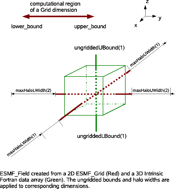
In this example, we will show how to create a 7D Field from a 5D ESMF_Grid and 2D ungridded bounds with arbitrary halo widths and gridToFieldMap.
We first create a 5D DistGrid and a 5D Grid based on the DistGrid; then ESMF_FieldGet computes the shape of a 7D array in fsize. We can then create a 7D Field from the 5D Grid and the 7D Fortran data array with other assimilating parameters.
    ! create a 5d distgrid
    distgrid5d = ESMF_DistGridCreate(minIndex=(/1,1,1,1,1/), &
        maxIndex=(/10,4,10,4,6/), regDecomp=(/2,1,2,1,1/), rc=rc)
    if (rc.NE.ESMF_SUCCESS) finalrc = ESMF_FAILURE

    ! Create a 5d Grid
    grid5d = ESMF_GridCreate(distgrid=distgrid5d, name="grid", rc=rc)
    if (rc.NE.ESMF_SUCCESS) finalrc = ESMF_FAILURE

    ! use FieldGet to retrieve total counts
    call ESMF_FieldGet(grid5d, localDe=0, ungriddedLBound=(/1,2/), &
        ungriddedUBound=(/4,5/), &
        totalLWidth=(/1,1,1,2,2/), totalUWidth=(/1,2,3,4,5/), &
        gridToFieldMap=(/3,2,5,4,1/), &
        totalCount=fsize, &
        rc=rc)
    if (rc.NE.ESMF_SUCCESS) finalrc = ESMF_FAILURE

    ! allocate the 7d Fortran array based on retrieved total counts
    allocate(farray7d(fsize(1), fsize(2), fsize(3), fsize(4), fsize(5), &
			fsize(6), fsize(7)))

    ! create the Field
    field7d = ESMF_FieldCreate(grid5d, farray7d, ESMF_INDEX_DELOCAL, &
        ungriddedLBound=(/1,2/), ungriddedUBound=(/4,5/), &
        totalLWidth=(/1,1,1,2,2/), totalUWidth=(/1,2,3,4,5/), &
        gridToFieldMap=(/3,2,5,4,1/), &
        rc=rc)
    if (rc.NE.ESMF_SUCCESS) finalrc = ESMF_FAILURE
A user can allocate the Fortran array in a different manner using the lower and upper bounds returned from FieldGet through the optional totalLBound and totalUBound arguments. In the following example, we create another 7D Field by retrieving the bounds and allocate the Fortran array with this approach. In this scheme, indexing the Fortran array is sometimes more convenient than using the shape directly.
    call ESMF_FieldGet(grid5d, localDe=0, ungriddedLBound=(/1,2/), &
        ungriddedUBound=(/4,5/), &
        totalLWidth=(/1,1,1,2,2/), totalUWidth=(/1,2,3,4,5/), &
        gridToFieldMap=(/3,2,5,4,1/), &
        totalLBound=flbound, totalUBound=fubound, &
        rc=rc)
    if (rc.NE.ESMF_SUCCESS) finalrc = ESMF_FAILURE

    allocate(farray7d2(flbound(1):fubound(1), flbound(2):fubound(2), &
		       flbound(3):fubound(3), flbound(4):fubound(4), &
		       flbound(5):fubound(5), flbound(6):fubound(6), &
                       flbound(7):fubound(7)) )

    field7d2 = ESMF_FieldCreate(grid5d, farray7d2, ESMF_INDEX_DELOCAL, &
        ungriddedLBound=(/1,2/), ungriddedUBound=(/4,5/), &
        totalLWidth=(/1,1,1,2,2/), totalUWidth=(/1,2,3,4,5/), &
        gridToFieldMap=(/3,2,5,4,1/), &
        rc=rc)
    if (rc.NE.ESMF_SUCCESS) finalrc = ESMF_FAILURE
A user can create an ESMF_Field directly from an ESMF_Grid and an intrinsic Fortran data array. This interface is overloaded for typekind and rank of the Fortran data array.
In the following example, each dimension size of the Fortran array is equal to the exclusive bounds of its corresponding Grid dimension queried from the Grid through ESMF_GridGet() public interface.
Formally let fa_shape(i) be the shape of i-th dimension of user supplied Fortran array, then rule 1 states:
    (1) fa_shape(i) = exclusiveCount(i)
                  i = 1...GridDimCount
fa_shape(i) defines the shape of i-th dimension of the Fortran array. ExclusiveCount are the number of data elements of i-th dimension in the exclusive region queried from ESMF_GridGet interface. Rule 1 assumes that the Grid and the Fortran intrinsic array have same number of dimensions; and optional arguments of FieldCreate from Fortran array are left unspecified using default setup. These assumptions are true for most typical use of FieldCreate from Fortran data array. This is the easiest way to create a Field from a Grid and Fortran intrinsic data array.
Fortran array dimension sizes (called shape in most Fortran language books) are equivalent to the bounds and counts used in this manual. The following equation holds:
fa_shape(i) = shape(i) = counts(i) = upper_bound(i) - lower_bound(i) + 1
These typically mean the same concept unless specifically explained to mean something else. For example, ESMF uses DimCount very often to mean number of dimensions instead of its meaning implied in the above equation. We'll clarify the meaning of a word when ambiguity could occur.
Rule 1 is most useful for a user working with Field creation from a Grid and a Fortran data array in most scenarios. It extends to higher dimension count, 3D, 4D, etc... Typically, as the code example demonstrates, a user first creates a Grid , then uses ESMF_GridGet() to retrieve the exclusive counts. Next the user calculates the shape of each Fortran array dimension according to rule 1. The Fortran data array is allocated and initialized based on the computed shape. A Field can either be created in one shot created empty and finished using ESMF_FieldSetCommit.
There are important details that can be skipped but are good to know for ESMF_FieldSetCommit
and ESMF_FieldCreate from a Fortran data array. 1) these methods require each PET contains
exactly one DE. This implies that a code using FieldCreate from a data array or FieldSetCommit must
have the same number of DEs and PETs, formally
![]() . Violation of this condition
will cause run time failures. 2) the bounds and counts retrieved from GridGet are DE specific
or equivalently PET specific, which means that the Fortran array shape could be different from one
PET to another.
. Violation of this condition
will cause run time failures. 2) the bounds and counts retrieved from GridGet are DE specific
or equivalently PET specific, which means that the Fortran array shape could be different from one
PET to another.
    grid = ESMF_GridCreateShapeTile(minIndex=(/1,1/), maxIndex=(/10,20/), &
          regDecomp=(/2,2/), name="atmgrid", rc=rc)
    if (rc.NE.ESMF_SUCCESS) finalrc = ESMF_FAILURE

    call ESMF_GridGet(grid, localDE=0, staggerloc=ESMF_STAGGERLOC_CENTER, &
        exclusiveCount=gec, rc=rc)
    if (rc.NE.ESMF_SUCCESS) finalrc = ESMF_FAILURE

    allocate(farray(gec(1), gec(2)) )

    field = ESMF_FieldCreate(grid, farray, ESMF_INDEX_DELOCAL, rc=rc)
    if(rc .ne. ESMF_SUCCESS) finalrc = ESMF_FAILURE
The setup of this example is similar to the previous section except that the Field is created from a data pointer instead of a data array. We highlight the ability to deallocate the internal fortran data pointer queried from the Field. This gives a user more flexibility with memory management.
    allocate(farrayPtr(gec(1), gec(2)) )

    field = ESMF_FieldCreate(grid, farrayPtr, rc=rc)
    if(rc .ne. ESMF_SUCCESS) finalrc = ESMF_FAILURE
    call ESMF_FieldGet(field, farrayPtr=farrayPtr2, rc=rc)
    if(rc .ne. ESMF_SUCCESS) finalrc = ESMF_FAILURE
    ! deallocate the retrieved fortran array pointer
    deallocate(farrayPtr2)
This example demonstrates a typical use of ESMF_Field combining a 2D grid and a 3D Fortran native data array. One immediate problem follows: how does one define the bounds of the ungridded dimension? This is solved by the optional arguments ungriddedLBound and ungriddedUBound of the ESMF_FieldCreate interface. By definition, ungriddedLBound and ungriddedUBound are both 1 dimensional integer Fortran arrays.
Formally, let fa_shape(j=1...FieldDimCount-GridDimCount) be the shape of the ungridded dimensions of a Field relative to the Grid used in Field creation. The Field dimension count is equal to the number of dimensions of the Fortran array, which equals the number of dimensions of the resultant Field. GridDimCount is the number of dimensions of the Grid.
fa_shape(j) is computed as:
fa_shape(j) = ungriddedUBound(j) - ungriddedLBound(j) + 1
fa_shape is easy to compute when the gridded and ungridded dimensions do not mix. However, it's conceivable that at higher dimension count, gridded and ungridded dimensions can interleave. To aid the computation of ungridded dimension shape we formally introduce the mapping concept.
Let
![]() , and
, and
![]() .
. ![]() is the number
of elements in set A,
is the number
of elements in set A, ![]() is the number of elements in set B.
is the number of elements in set B. ![]() defines
a mapping from i-th element of set A to
defines
a mapping from i-th element of set A to ![]() -th element in set B.
-th element in set B. ![]() indicates there does not exist a mapping from i-th element of set A to set B.
indicates there does not exist a mapping from i-th element of set A to set B.
Suppose we have a mapping from dimension index of ungriddedLBound (or
ungriddedUBound) to Fortran array dimension index, called ugb2fa.
By definition, ![]() equals to the dimension count of
ungriddedLBound (or ungriddedUBound),
equals to the dimension count of
ungriddedLBound (or ungriddedUBound), ![]() equals to the dimension count of
the Fortran array. We can now formulate the computation of ungridded
dimension shape as rule 2:
equals to the dimension count of
the Fortran array. We can now formulate the computation of ungridded
dimension shape as rule 2:
    (2) fa_shape(ugb2fa(j)) = ungriddedUBound(j) - ungriddedLBound(j) + 1
                          j = 1..FortranArrayDimCount - GridDimCount
The mapping can be computed in linear time proportional to the Fortran array dimension count (or rank) using the following algorithm in pseudocode:
    map_index = 1
    do i = 1, farray_rank
        if i-th dimension of farray is ungridded
            ugb2fa(map_index) = i
            map_index = map_index + 1
        endif
    enddo
Here we use rank and dimension count interchangably. These 2 terminologies are typically equivalent. But there are subtle differences under certain conditions. Rank is the total number of dimensions of a tensor object. Dimension count allows a finer description of the heterogeneous dimensions in that object. For example, A Field of rank 5 can have 3 gridded dimensions and 2 ungridded dimensions. Rank is precisely the summation of dimension count of all types of dimensions.
For example, if a 5D array is used with a 3D Grid, there are 2 ungridded dimensions: ungriddedLBound=(/1,2/) and ungriddedUBound=(/5,7/). Suppose the distribution of dimensions look like (O, X, O, X, O), O means gridded, X means ungridded. Then the mapping from ungridded bounds to Fortran array is ugb2fa=(/2, 4/). The shape of 2nd and 4th dimension of Fortran array should equal (5, 8).
Back to our 3D Field created from a 2D Grid and 3D Fortran array example, suppose the 3rd Field dimension is ungridded, ungriddedLBound=(/3/), ungriddedUBound=(/9/). First we use rule 1 to compute shapes of the gridded Fortran array dimension, then we use rule 2 to compute shapes of the ungridded Fortran array dimension. In this example, we used the exclusive bounds obtained in the previous example.
    fa_shape(1) = gec(1) ! rule 1
    fa_shape(2) = gec(2)
    fa_shape(3) = 7 ! rule 2 9-3+1
    allocate(farray3d(fa_shape(1), fa_shape(2), fa_shape(3)))
    field = ESMF_FieldCreate(grid, farray3d, ESMF_INDEX_DELOCAL, &
        ungriddedLBound=(/3/), ungriddedUBound=(/9/), &
        rc=rc)
    if(rc .ne. ESMF_SUCCESS) finalrc = ESMF_FAILURE
Building upon the previous example, we will create a 3D Field from a 2D grid and 3D array but with a slight twist. In this example, we introduce the gridToFieldMap argument that allows a user to map Grid dimension index to Field dimension index.
In this example, both dimensions of the Grid are distributed and the mapping from DistGrid to Grid is (/1,2/). We will introduce rule 3 assuming distgridToGridMap=(/1,2,3...gridDimCount/), and distgridDimCount equals to gridDimCount. This is a reasonable assumption in typical Field use.
We apply the mapping gridToFieldMap on rule 1 to create rule 3:
    (3) fa_shape(gridToFieldMap(i)) = exclusiveCount(i)
                                  i = 1,..GridDimCount.
Back to our example, suppose the 2nd Field dimension is ungridded, ungriddedLBound=(/3/), ungriddedUBound=(/9/). gridToFieldMap=(/3,1/), meaning the 1st Grid dimension maps to 3rd Field dimension, and 2nd Grid dimension maps to 1st Field dimension.
First we use rule 3 to compute shapes of the gridded Fortran array dimension, then we use rule 2 to compute shapes of the ungridded Fortran array dimension. In this example, we use the exclusive bounds obtained in the previous example.
    gridToFieldMap2d(1) = 3
    gridToFieldMap2d(2) = 1
    do i = 1, 2
        fa_shape(gridToFieldMap2d(i)) = gec(i)
    end do
    fa_shape(2) = 7
    allocate(farray3d(fa_shape(1), fa_shape(2), fa_shape(3)))
    field = ESMF_FieldCreate(grid, farray3d, ESMF_INDEX_DELOCAL, &
        ungriddedLBound=(/3/), ungriddedUBound=(/9/), &
        gridToFieldMap=gridToFieldMap2d, &
        rc=rc)
    if(rc .ne. ESMF_SUCCESS) finalrc = ESMF_FAILURE
This example is similar to example 20.3.12, in addition we will show a user can associate different halo width to a Fortran array to create a Field through the totalLWidth and totalUWidth optional arguments. A diagram of the dimension configuration from Grid, halos, and Fortran data array is shown here.
The ESMF_FieldCreate() interface supports creating a Field from a Grid and a Fortran array padded with halos on the distributed dimensions of the Fortran array. Using this technique one can avoid passing non-contiguous Fortran array slice to FieldCreate. It guarantees the same exclusive region, and by using halos, it also defines a bigger total region to contain the entire contiguous memory block of the Fortran array.
The elements of totalLWidth and totalUWidth are applied in the order distributed dimensions appear in the Fortran array. By definition, totalLWidth and totalUWidth are 1 dimensional arrays of non-negative integer values. The size of haloWidth arrays is equal to the number of distributed dimensions of the Fortran array, which is also equal to the number of distributed dimensions of the Grid used in the Field creation.
Because the order of totalWidth (representing both totalLWidth and totalUWidth) element is applied to the order distributed dimensions appear in the Fortran array dimensions, it's quite simple to compute the shape of distributed dimensions of the Fortran array. They are done in a similar manner when applying ungriddedLBound and ungriddedUBound to ungridded dimensions of the Fortran array defined by rule 2.
Assume we have the mapping from the dimension index of totalWidth to the dimension index of Fortran array, called mhw2fa; and we also have the mapping from dimension index of Fortran array to dimension index of the Grid, called fa2g. The shape of distributed dimensions of a Fortran array can be computed by rule 4:
    (4) fa_shape(mhw2fa(k)) = exclusiveCount(fa2g(mhw2fa(k)) +
                              totalUWidth(k) + totalLWidth(k)
                          k = 1...size(totalWidth)
This rule may seem confusing but algorithmically the computation can be done by the following pseudocode:
    fa_index = 1
    do i = 1, farray_rank
       if i-th dimension of Fortran array is distributed
           fa_shape(i) = exclusiveCount(fa2g(i)) +
                         totalUWidth(fa_index) + totalLWidth(fa_index)
           fa_index = fa_index + 1
       endif
    enddo
The only complication then is to figure out the mapping from Fortran array dimension index to Grid dimension index. This process can be done by computing the reverse mapping from Field to Grid.
Typically, we don't have to consider these complications if the following conditions are met: 1) All Grid dimensions are distributed. 2) DistGrid in the Grid has a dimension index mapping to the Grid in the form of natural order (/1,2,3,.../). This natural order mapping is the default mapping between various objects throughout ESMF. 3) Grid to Field mapping is in the form of natural order, i.e. default mapping. These seem like a lot of conditions but they are the default case in the interaction among DistGrid, Grid, and Field. When these conditions are met, which is typically true, the shape of distributed dimensions of Fortran array follows rule 5 in a simple form:
    (5) fa_shape(k) = exclusiveCount(k) +
                      totalUWidth(k) + totalLWidth(k)
                  k = 1...size(totalWidth)
Let's examine an example on how to apply rule 5. Suppose we have a 5D array and a 3D Grid that has its first 3 dimensions mapped to the first 3 dimensions of the Fortran array. totalLWidth=(/1,2,3/), totalUWidth=(/7,9,10/), then by rule 5, the following pseudo code can be used to compute the shape of the first 3 dimensions of the Fortran array. The shape of the remaining two ungridded dimensions can be computed according to rule 2.
    do k = 1, 3
        fa_shape(k) = exclusiveCount(k) +
                      totalUWidth(k) + totalLWidth(k))
    enddo
Suppose now gridToFieldMap=(/2,3,4/) instead which says the first dimension of Grid maps to the 2nd dimension of Field (or Fortran array) and so on and so forth, we can obtain a more general form of rule 5 by introducing first_distdim_index shift when Grid to Field map (gridToFieldMap) is in the form of (/a,a+1,a+2.../).
    (6) fa_shape(k+first_distdim_index-1) = exclusiveCount(k) +
                                            totalUWidth(k) + totalLWidth(k)
                                        k = 1...size(totalWidth)
It's obvious that first_distdim_index=a. If the first dimension of the Fortran array is distributed, then rule 6 degenerates into rule 5, which is the typical case.
Back to our example creating a 3D Field from a 2D Grid and a 3D intrinsic Fortran array, we will use the Grid created from previous example that satisfies condition 1 and 2. We'll also use a simple gridToFieldMap (1,2) which is the default mapping that satisfies condition 3. First we use rule 5 to compute the shape of distributed dimensions then we use rule 2 to compute the shape of the ungridded dimensions.
    gridToFieldMap2d(1) = 1
    gridToFieldMap2d(2) = 2
    totalLWidth2d(1) = 3
    totalLWidth2d(2) = 4
    totalUWidth2d(1) = 3
    totalUWidth2d(2) = 5
    do k = 1, 2
        fa_shape(k) = gec(k) + totalLWidth2d(k) + totalUWidth2d(k)
    end do
    fa_shape(3) = 7          ! 9-3+1
    allocate(farray3d(fa_shape(1), fa_shape(2), fa_shape(3)))
    field = ESMF_FieldCreate(grid, farray3d, ESMF_INDEX_DELOCAL, &
        ungriddedLBound=(/3/), ungriddedUBound=(/9/), &
        totalLWidth=totalLWidth2d, totalUWidth=totalUWidth2d, &
        gridToFieldMap=gridToFieldMap2d, &
        rc=rc)
    if(rc .ne. ESMF_SUCCESS) finalrc = ESMF_FAILURE
In this example, an ESMF_Field is created from an ESMF_LocStream and typekind/rank. The location stream object is uniformly distributed in a 1 dimensional space on 4 DEs. The rank is 1 dimensional. Please refer to LocStream examples section for more information on LocStream creation.
    locs = ESMF_LocStreamCreate(minIndex=1, maxIndex=16, rc=rc)
    if (rc.NE.ESMF_SUCCESS) finalrc = ESMF_FAILURE

    field = ESMF_FieldCreate(locs, typekind=ESMF_TYPEKIND_I4, &
        rc=rc)
    if (rc.NE.ESMF_SUCCESS) finalrc = ESMF_FAILURE
In this example, an ESMF_Field is created from an ESMF_LocStream and an ESMF_Arrayspec. The location stream object is uniformly distributed in a 1 dimensional space on 4 DEs. The arrayspec is 1 dimensional. Please refer to LocStream examples section for more information on LocStream creation.
    locs = ESMF_LocStreamCreate(minIndex=1, maxIndex=16, rc=rc)
    if (rc.NE.ESMF_SUCCESS) finalrc = ESMF_FAILURE

    call ESMF_ArraySpecSet(arrayspec, 1, ESMF_TYPEKIND_I4, rc=rc)
    if (rc.NE.ESMF_SUCCESS) finalrc = ESMF_FAILURE

    field = ESMF_FieldCreate(locs, arrayspec, &
        rc=rc)
    if (rc.NE.ESMF_SUCCESS) finalrc = ESMF_FAILURE
In this example, an ESMF_Field is created from an ESMF_Mesh and typekind/rank. The mesh object is on a Euclidean surface that is partitioned to a 2x2 rectangular space with 4 elements and 9 nodes. The nodal space is represented by a distgrid with 9 indices. Field is created on locally owned nodes on each PET. Therefore, the created Field has 9 data points globally. The mesh object can be represented by the picture below. For more information on Mesh creation, please see Section 27.3.1.
                Mesh Ids

    2.0   7 ------- 8 -------- 9
          |         |          |
          |    3    |    4     |
          |         |          |
    1.0   4 ------- 5 -------- 6
          |         |          |
          |    1    |    2     |
          |         |          |
    0.0   1 ------- 2 -------- 3

         0.0       1.0        2.0

        Node Ids at corners
        Element Ids in centers


               Mesh Owners

    2.0   2 ------- 2 -------- 3
          |         |          |
          |    2    |    3     |
          |         |          |
    1.0   0 ------- 0 -------- 1
          |         |          |
          |    0    |    1     |
          |         |          |
    0.0   0 ------- 0 -------- 1

         0.0       1.0        2.0

        Node Owners at corners
        Element Owners in centers
      ! Create Mesh structure in 1 step
      mesh=ESMF_MeshCreate(parametricDim=2,spatialDim=2, &
             nodeIds=nodeIds, nodeCoords=nodeCoords, &
             nodeOwners=nodeOwners, elementIds=elemIds,&
             elementTypes=elemTypes, elementConn=elemConn, &
             rc=rc)
      if(rc .ne. ESMF_SUCCESS) finalrc = ESMF_FAILURE

      ! Field is created on the 1 dimensinonal nodal distgrid. On
      ! each PET, Field is created on the locally owned nodes.
      field = ESMF_FieldCreate(mesh, typekind=ESMF_TYPEKIND_I4, rc=rc)
      if(rc .ne. ESMF_SUCCESS) finalrc = ESMF_FAILURE
In this example, an ESMF_Field is created from an ESMF_Mesh and an ESMF_Arrayspec. The mesh object is on a Euclidean surface that is partitioned to a 2x2 rectangular space with 4 elements and 9 nodes. The nodal space is represented by a distgrid with 9 indices. Field is created on locally owned nodes on each PET. Therefore, the created Field has 9 data points globally. The mesh object can be represented by the picture below. For more information on Mesh creation, please see Section 27.3.1.
      ! Create Mesh structure in 1 step
      mesh=ESMF_MeshCreate(parametricDim=2,spatialDim=2, &
             nodeIds=nodeIds, nodeCoords=nodeCoords, &
             nodeOwners=nodeOwners, elementIds=elemIds,&
             elementTypes=elemTypes, elementConn=elemConn, &
             rc=rc)
      if(rc .ne. ESMF_SUCCESS) finalrc = ESMF_FAILURE

      call ESMF_ArraySpecSet(arrayspec, 1, ESMF_TYPEKIND_I4, rc=rc)
      if(rc .ne. ESMF_SUCCESS) finalrc = ESMF_FAILURE

      ! Field is created on the 1 dimensinonal nodal distgrid. On
      ! each PET, Field is created on the locally owned nodes.
      field = ESMF_FieldCreate(mesh, arrayspec, rc=rc)
      if(rc .ne. ESMF_SUCCESS) finalrc = ESMF_FAILURE
In this example, an ESMF_Field is created from an ESMF_Mesh and an ESMF_Array. The mesh object is created in the previous example and the array object is retrieved from the field created in the previous example too.
    call ESMF_MeshGet(mesh, nodalDistgrid=distgrid, rc=rc)
    if (rc.NE.ESMF_SUCCESS) finalrc = ESMF_FAILURE
    array = ESMF_ArrayCreate(distgrid=distgrid, arrayspec=arrayspec, rc=rc)
    if (rc.NE.ESMF_SUCCESS) finalrc = ESMF_FAILURE
    ! query the array from the previous example
    call ESMF_FieldGet(field, array=array, rc=rc)
    if (rc.NE.ESMF_SUCCESS) finalrc = ESMF_FAILURE
    ! create a Field from a mesh and an array
    field1 = ESMF_FieldCreate(mesh, array, rc=rc)
    if (rc.NE.ESMF_SUCCESS) finalrc = ESMF_FAILURE
In this example, an ESMF_Field is created from an ESMF_Mesh and an ESMF_ArraySpec. The mesh object is created in the previous example. The Field is also created with optional arguments such as ungridded dimensions and dimension mapping.
In this example, the mesh is mapped to the 2nd dimension of the ESMF_Field, with its first dimension being the ungridded dimension with bounds 1,3.
    call ESMF_ArraySpecSet(arrayspec, 2, ESMF_TYPEKIND_I4, rc=rc)
    field = ESMF_FieldCreate(mesh, arrayspec=arrayspec, gridToFieldMap=(/2/), &
        ungriddedLBound=(/1/), ungriddedUBound=(/3/), rc=rc)
    if (rc.NE.ESMF_SUCCESS) finalrc = ESMF_FAILURE
In this example an ESMF_Field with replicated dimension is created from an ESMF_Grid and an ESMF_Arrayspec. A user can also use other ESMF_FieldCreate() methods to create replicated dimension Field, this example illustrates the key concepts and use of a replicated dimension Field.
Normally gridToFieldMap argument in ESMF_FieldCreate() should not contain 0 value entries. However, for Field with replicated dimension, a 0 entry in gridToFieldMap indicates the corresponding Grid dimension is replicated in the Field. In such a Field, the rank of the Field is no longer necessarily greater than its Grid rank. An example will make this clear. We will start by creating Distgrid and Grid.
    ! create 4D distgrid
    distgrid = ESMF_DistGridCreate(minIndex=(/1,1,1,1/), &
        maxIndex=(/6,4,6,4/), regDecomp=(/2,1,2,1/), rc=rc)
    if (rc.NE.ESMF_SUCCESS) finalrc = ESMF_FAILURE

    ! create 4D grid on top of the 4D distgrid
    grid = ESMF_GridCreate(distgrid=distgrid, name="grid", rc=rc)
    if (rc.NE.ESMF_SUCCESS) finalrc = ESMF_FAILURE

    ! create 3D arrayspec
    call ESMF_ArraySpecSet(arrayspec, 3, ESMF_TYPEKIND_R8, rc=rc)
    if (rc.NE.ESMF_SUCCESS) finalrc = ESMF_FAILURE
In this example, a user creates a 3D Field with replicated dimension replicated along the 2nd and 4th dimension of its underlying 4D Grid. In addition, the 2nd dimension of the Field is ungridded (why?). The 1st and 3rd dimensions of the Field have halos.
    ! create field, 2nd and 4th dimensions of the Grid are replicated
    field = ESMF_FieldCreate(grid, arrayspec, indexflag=ESMF_INDEX_DELOCAL, &
        gridToFieldMap=(/1,0,2,0/), &
        ungriddedLBound=(/1/), ungriddedUBound=(/4/), &
        totalLWidth=(/1,1/), totalUWidth=(/4,5/), &
        staggerloc=ESMF_STAGGERLOC_CORNER, &
        rc=rc)
    if (rc.NE.ESMF_SUCCESS) finalrc = ESMF_FAILURE

    ! get basic information from the field
    call ESMF_FieldGet(field, grid=grid1, array=array, typekind=typekind, &
        dimCount=dimCount, staggerloc=lstaggerloc, &
        gridToFieldMap=lgridToFieldMap, ungriddedLBound=lungriddedLBound, &
        ungriddedUBound=lungriddedUBound, totalLWidth=ltotalLWidth, &
        totalUWidth=ltotalUWidth, rc=rc)
    if (rc.NE.ESMF_SUCCESS) finalrc = ESMF_FAILURE

    ! get bounds information from the field
    call ESMF_FieldGet(field, localDe=0, farrayPtr=farray, &
        exclusiveLBound=felb, exclusiveUBound=feub, exclusiveCount=fec, &
        computationalLBound=fclb, computationalUBound=fcub, &
        computationalCount=fcc, totalLBound=ftlb, totalUBound=ftub, &
        totalCount=ftc, rc=rc)
    if (rc.NE.ESMF_SUCCESS) finalrc = ESMF_FAILURE
Next we verify that the field and array bounds agree with each other
    call ESMF_ArrayGet(array, rank=arank, dimCount=adimCount, rc=rc)
    if (rc.NE.ESMF_SUCCESS) finalrc = ESMF_FAILURE

    gridrank_repdim = 0
    do i = 1, size(gridToFieldMap)
        if(gridToFieldMap(i) == 0) gridrank_repdim = gridrank_repdim + 1
    enddo
Number of undistributed dimension of the array X is computed from total rank of the array A, the dimension count of its underlying distgrid B and number of replicated dimension in the distgrid C. We have the following formula: X = A - (B - C)
    allocate(audlb(arank-adimCount+gridrank_repdim), &
	audub(arank-adimCount+gridrank_repdim))
    call ESMF_ArrayGet(array, exclusiveLBound=aelb, exclusiveUBound=aeub, &
        computationalLBound=aclb, computationalUBound=acub, &
        totalLBound=atlb, totalUBound=atub, &
        undistLBound=audlb, undistUBound=audub, &
        rc=rc)
    if (rc.NE.ESMF_SUCCESS) finalrc = ESMF_FAILURE

    ! verify the ungridded bounds from field match
    ! undistributed bounds from its underlying array
    do i = 1, arank-adimCount
        if(lungriddedLBound(i) .ne. audlb(i) ) &
            rc = ESMF_FAILURE
    enddo
    if (rc.NE.ESMF_SUCCESS) finalrc = ESMF_FAILURE

    do i = 1, arank-adimCount
        if(lungriddedUBound(i) .ne. audub(i) ) &
            rc = ESMF_FAILURE
    enddo
    if (rc.NE.ESMF_SUCCESS) finalrc = ESMF_FAILURE
We then verify the data in the replicated dimension Field can be updated and accessed.
    do ik = ftlb(3), ftub(3)
     do ij = ftlb(2), ftub(2)
      do ii = ftlb(1), ftub(1)
        farray(ii,ij,ik) = ii+ij*2+ik
      enddo
     enddo
    enddo
    ! access and verify
    call ESMF_FieldGet(field, localDe=0, farrayPtr=farray1, &
        rc=rc)
    if (rc.NE.ESMF_SUCCESS) finalrc = ESMF_FAILURE
    do ik = ftlb(3), ftub(3)
     do ij = ftlb(2), ftub(2)
      do ii = ftlb(1), ftub(1)
        n = ii+ij*2+ik
        if(farray1(ii,ij,ik) .ne. n ) rc = ESMF_FAILURE
      enddo
     enddo
    enddo
    if (rc.NE.ESMF_SUCCESS) finalrc = ESMF_FAILURE

    ! release resources
    call ESMF_FieldDestroy(field)
    call ESMF_GridDestroy(grid)
    call ESMF_DistGridDestroy(distgrid)
With the introduction of Field on arbitrarily distributed Grid, Field has two kinds of dimension count: one associated geometrical (or physical) dimensionality, the other one associated with its memory index space representation. Field and Grid dimCount reflect the physical index space of the objects. A new type of dimCount rank should be added to both of these entities. rank gives the number of dimensions of the memory index space of the objects. This would be the dimension of the pointer pulled out of Field and the size of the bounds vector, for example.
For non-arbitrary Grids rank=dimCount, but for grids and fields with arbitrary dimensions rank = dimCount - (number of Arb dims) + 1 (Internally Field can use the Arb info from the grid to create the mapping from the Field Array to the DistGrid)
When creating a Field size(GridToFieldMap)=dimCount for both Arb and Non-arb grids This array specifies the mapping of Field to Grid identically for both Arb and Nonarb grids If a zero occurs in an entry corresponding to any arbitrary dimension, then a zero must occur in every entry corresponding to an arbitrary dimension (i.e. all arbitrary dimensions must either be all replicated or all not replicated, they can't be broken apart).
In this example an ESMF_Field is created from an arbitrarily distributed ESMF_Grid and an ESMF_Arrayspec. A user can also use other ESMF_FieldCreate() methods to create such a Field, this example illustrates the key concepts and use of Field on arbitrary distributed Grid.
The Grid is 3 dimensional in physics index space but the first two dimension are collapsed into a single memory index space. Thus the result Field is 3D in physics index space and 2D in memory index space. This is made obvious with the 2D arrayspec used to create this Field.
    ! create a 3D grid with the first 2 dimensions collapsed
    ! and arbitrarily distributed
    grid3d = ESMF_GridCreateShapeTile(coordTypeKind=ESMF_TYPEKIND_R8, &
      minIndex=(/1,1,1/), maxIndex=(/xdim, ydim,zdim/), &
      arbIndexList=localArbIndex,arbIndexCount=localArbIndexCount, &
      name="arb3dgrid", rc=rc)
    if(rc .ne. ESMF_SUCCESS) finalrc = ESMF_FAILURE

    ! create a 2D arrayspec
    call ESMF_ArraySpecSet(arrayspec2D, rank=2, typekind=ESMF_TYPEKIND_R4, &
         rc=rc)
    if(rc .ne. ESMF_SUCCESS) finalrc = ESMF_FAILURE

    ! create a 2D Field using the Grid and the arrayspec
    field = ESMF_FieldCreate(grid3d, arrayspec2D, rc=rc)
    if(rc .ne. ESMF_SUCCESS) finalrc = ESMF_FAILURE

    call ESMF_FieldGet(field, rank=rank, dimCount=dimCount, &
                       rc=rc)
    if (myPet .eq. 0) print *, 'Field rank, dimCount', &
                                rank, dimCount
    if(rc .ne. ESMF_SUCCESS) finalrc = ESMF_FAILURE

    ! verify that the dimension counts are correct
    if (rank .ne. 2) correct = .false.
    if (dimCount .ne. 3) correct = .false.
The next example is slightly more complicated in that the Field also contains ungridded dimension and its gridded dimension is replicated on the arbitrarily distributed dimension of the Grid.
The same 3D Grid and 2D arrayspec in the previous example are used but a gridToFieldMap argument is supplied to the ESMF_FieldCreate() call. The first 2 entries of the map are 0, the last (3rd) entry is 1. The 3rd dimension of the Grid is mapped to the first dimension of the Field, this dimension is then replicated on the arbitrarily distributed dimensions of the Grid. In addition, the Field also has one ungridded dimension. Thus the final dimension count of the Field is 2 in both physics and memory index space.
    field = ESMF_FieldCreate(grid3d, arrayspec2D,gridToFieldMap=(/0,0,1/), &
            ungriddedLBound=(/1/), ungriddedUBound=(/10/),rc=rc)
    if(rc .ne. ESMF_SUCCESS) finalrc = ESMF_FAILURE

    call ESMF_FieldGet(field, rank=rank, dimCount=dimCount, &
                       rc=rc)
    if (myPet .eq. 0) print *, 'Field rank, dimCount', &
                                rank, dimCount
    if(rc .ne. ESMF_SUCCESS) finalrc = ESMF_FAILURE

    if (rank .ne. 2) correct = .false.
    if (dimCount .ne. 2) correct = .false.
The Field regrid operation moves data between Fields which lie on different Grids. In order to do this the data in the source Field is interpolated to the destination Grid and then put into the destination Field. In ESMF the regrid operation is implemented as a sparse matrix multiply. The ESMF_FieldRegridStore() call generates the sparse matrix for the regrid operation. This matrix may be either retrieved in a factor and index raw form, or may be retrieved in the form of a routeHandle which contains an internal representation of the communication and mathermatical operations necessary to perform the regrid. Note ESMF_FieldRegridStore() assumes the latitude and longitude coordinates of the grid are in degrees. The routeHandle can then be used in an ESMF_FieldRegrid() call to perform the interpolation between the two Fields. The routeHandle depends only on the coordinates in the Grids where the Fields are built, so as long as the coordinates stay the same, the operation can be performed multiple times using the same routeHandle. This is true even if the Field data changes. The same routeHandle may also be used to interpolate between any source and destination Field which lie on the same stagger location and Grid as the original Fields. When it's no longer needed the routeHandle should be destroyed by using ESMF_FieldRegridRelease() to free the memory it's using.
There are two options for accessing ESMF regridding functionality: online and offline. Online regridding means that the weights are generated via subroutine calls during the execution of the users code. This is the method described in the following sections. Offline regridding means that the weights are generated by a seperate application from the user code. Please see Section 12 for a description of the offline regridding application and the options it supports.
ESMF currently supports regridding only on a subset of the full range of Grids and Meshes it supports.
In 2D ESMF supports regridding between any combination of the following:
In 3D ESMF supports regridding between any combination of the following:
In terms of masking, ESMF regrid currently supports masking for Fields built on structured Grids. The user may mask out points in the source Field or destination Field or both. The user also has the option to return an error for unmapped destination points or to ignore them. At this point ESMF does not support extrapolation to destination points outside the unmasked source Field.
ESMF currently supports three options for interpolation: bilinear, patch, and conservative. Bilinear interpolation calculates the value for the destination point as a combination of multiple linear interpolations, one for each dimension of the Grid. Note that for ease of use, the term bilinear interpolation is used for 3D interpolation in ESMF as well, although it should more properly be referred to as trilinear interpolation.
Patch (or higher-order) interpolation is the ESMF version of a techique called ``patch recovery'' commonly used in finite element modeling [3] [7]. It typically results in better approximations to values and derivatives when compared to bilinear interpolation. Patch interpolation works by constructing multiple polynomial patches to represent the data in a source cell. For 2D grids, these polynomials are currently 2nd degree 2D polynomials. One patch is constructed for each corner of the source cell, and the patch is constructed by doing a least squared fit through the data in the cells surrounding the corner. The interpolated value at the destination point is then a weighted average of the values of the patches at that point. The patch method has a larger stencil than the bilinear, for this reason the patch weight matrix can be correspondingly larger than the bilinear matrix (e.g. for a quadrilateral grid the patch matrix is around 4x the size of the bilinear matrix). This can be an issue when performing a regrid operation close to the memory limit on a machine.
First-order conservative interpolation [16] is also available as a regridding method. This method will typically have a larger interpolation error than the previous two methods, but will do a much better job of preserving the value of the integral of data between the source and destination grid. In this method the value across each source cell is treated as a constant. The weights for a particular destination cell, are the area of intersection of each source cell with the destination cell divided by the area of the destination cell. Areas in this case are the great circle areas of the polygons which make up the cells (the cells around each center are defined by the corner coordinates in the grid file). To use this method the user must have created their Fields on the center stagger location (ESMF_STAGGERLOC_CENTER) for Grids or the element location (ESMF_MESHLOC_ELEMENT) for Meshes. For Grids, the corner stagger location (ESMF_STAGGERLOC_CORNER) must contain coordinates describing the outer perimeter of the Grid cells. Currently conservative interpolation is only supported for 2D Grids and Meshes.
The following sections give examples of using the regridding functionality.
  call ESMF_FieldRegridStore(srcField=srcField, dstField=dstField, &
                  routeHandle=routeHandle, &
                  indicies=indicies, weights=weights, &
                  regridMethod=ESMF_REGRID_METHOD_BILINEAR, rc=localrc)
call ESMF_FieldRegrid(srcField, dstField, routeHandle, rc=localrc)
call ESMF_FieldRegridRelease(routeHandle, rc=localrc)
  call ESMF_FieldRegridStore(srcField=srcField, srcMaskValues=(/1/),       &
                             dstField=dstField, dstMaskValues=(/1/),       &
                             unmappedDstAction=ESMF_UNMAPPEDACTION_IGNORE, &
                             routeHandle=routeHandle,                      &
                             indicies=indicies, weights=weights,           &
                             regridMethod=ESMF_REGRID_METHOD_BILINEAR,     &
                             rc=localrc)
The ESMF_FieldRegrid and ESMF_FieldRegridRelease calls may then be applied as in the previous example.
The below is a list of problems users commonly encounter with regridding and potential solutions. This is by no means an exhaustive list, so if none of these problems fit your case, or if the solutions don't fix your problem, please feel free to email esmf support (esmf_support@list.woc.noaa.gov).
Problem: Regridding is too slow.
Possible Cause: The ESMF_FieldRegridStore() method is called more than is necessary.
The ESMF_FieldRegridStore() operation is a complex one and can be
relatively slow for some cases (large Grids, 3D grids, etc.)
Solution: Reduce the number of ESMF_FieldRegridStore() calls to the minimum necessary. The routeHandle generated by the ESMF_FieldRegridStore() call depends on only four factors: the stagger locations that the input Fields are created on, the coordinates in the Grids the input Fields are built on at those stagger locations, the padding of the input Fields (specified by the totalWidth arguments in FieldCreate) and the size of the tensor dimensions in the input Fields (specified by the ungridded arguments in FieldCreate). For any pair of Fields which share these attributes with the Fields used in the ESMF_FieldRegridStore call the same routeHandle can be used. Note, that the data in the Fields does NOT matter, the same routeHandle can be used no matter how the data in the Fields changes.
In particular:
Problem: Distortions in destination Field at periodic boundary.
Possible Cause: The Grid overlaps itself. With a periodic Grid, the regrid system expects the first point to not be a repeat of the last point. In other words, regrid constructs its own connection and overlap between the first and last points of the periodic dimension and so the Grid doesn't need to contain these. If the Grid does, then this can cause problems.
Solution: Define the Grid so that it doesn't contain the overlap point. This typically means simply making the Grid one point smaller in the periodic dimension. If a Field constructuted on the Grid needs to contain these overlap points then the user can use the totalWidth arguments to include this extra padding in the Field. Note, however, that the regrid won't update these extra points, so the user will have to do a copy to fill the points in the overlap region in the Field.
  !!!!!!!!!!!!!!!!!!!!!!!!!!!!!!!!!!!!!!!!!!!!!!!
  ! Create Source Mesh
  !!!!!!!!!!!!!!!!!!!!!!!!!!!!!!!!!!!!!!!!!!!!!!!

  ! Create the Mesh structure.
  ! For brevity's sake, the code to fill the Mesh creation
  ! arrays is omitted from this example. However, here
  ! is a brief description of the arrays:
  ! srcNodeIds    - the global ids for the src nodes
  ! srcNodeCoords - the coordinates for the src nodes
  ! srcNodeOwners - which PET owns each src node
  ! srcElemIds    - the global ids of the src elements
  ! srcElemTypes  - the topological shape of each src element
  ! srcElemConn   - how to connect the nodes to form the elements
  !                 in the source mesh
  ! Several examples of setting up these arrays can be seen in
  ! the Mesh Section "Mesh Creation".
  srcMesh=ESMF_MeshCreate(parametricDim=2,spatialDim=2, &
         nodeIds=srcNodeIds, nodeCoords=srcNodeCoords, &
         nodeOwners=srcNodeOwners, elementIds=srcElemIds,&
         elementTypes=srcElemTypes, elementConn=srcElemConn, rc=rc)


  !!!!!!!!!!!!!!!!!!!!!!!!!!!!!!!!!!!!!!!!!!!!!!!
  ! Create and Fill Source Field
  !!!!!!!!!!!!!!!!!!!!!!!!!!!!!!!!!!!!!!!!!!!!!!!

  ! Set description of source Field
  call ESMF_ArraySpecSet(arrayspec, 1, ESMF_TYPEKIND_R8, rc=rc)

  ! Create source Field
  srcField = ESMF_FieldCreate(srcMesh, arrayspec, &
                        name="source", rc=rc)

  ! Get source Field data pointer to put data into
  call ESMF_FieldGet(srcField, 0, fptr1D,  rc=rc)

  ! Get number of local nodes to allocate space
  ! to hold local node coordinates
  call ESMF_MeshGet(srcMesh, &
         numOwnedNodes=numOwnedNodes, rc=rc)

  ! Allocate space to hold local node coordinates
  ! (spatial dimension of Mesh*number of local nodes)
  allocate(ownedNodeCoords(2*numOwnedNodes))

  ! Get local node coordinates
  call ESMF_MeshGet(srcMesh, &
         ownedNodeCoords=ownedNodeCoords, rc=rc)

  ! Set the source Field to the function 20.0+x+y
  do i=1,numOwnedNodes
    ! Get coordinates
    x=ownedNodeCoords(2*i-1)
    y=ownedNodeCoords(2*i)

   ! Set source function
   fptr1D(i) = 20.0+x+y
  enddo

  ! Deallocate local node coordinates
  deallocate(ownedNodeCoords)


  !!!!!!!!!!!!!!!!!!!!!!!!!!!!!!!!!!!!!!!!!!!!!!!
  ! Create Destination Mesh
  !!!!!!!!!!!!!!!!!!!!!!!!!!!!!!!!!!!!!!!!!!!!!!!

  ! Create the Mesh structure.
  ! For brevity's sake, the code to fill the Mesh creation
  ! arrays is omitted from this example. However, here
  ! is a brief description of the arrays:
  ! dstNodeIds    - the global ids for the dst nodes
  ! dstNodeCoords - the coordinates for the dst nodes
  ! dstNodeOwners - which PET owns each dst node
  ! dstElemIds    - the global ids of the dst elements
  ! dstElemTypes  - the topological shape of each dst element
  ! dstElemConn   - how to connect the nodes to form the elements
  !                 in the destination mesh
  ! Several examples of setting up these arrays can be seen in
  ! the Mesh Section "Mesh Creation".
  dstMesh=ESMF_MeshCreate(parametricDim=2,spatialDim=2, &
         nodeIds=dstNodeIds, nodeCoords=dstNodeCoords, &
         nodeOwners=dstNodeOwners, elementIds=dstElemIds,&
         elementTypes=dstElemTypes, elementConn=dstElemConn, rc=rc)


  !!!!!!!!!!!!!!!!!!!!!!!!!!!!!!!!!!!!!!!!!!!!!!!
  ! Create Destination Field
  !!!!!!!!!!!!!!!!!!!!!!!!!!!!!!!!!!!!!!!!!!!!!!!

  ! Set description of source Field
  call ESMF_ArraySpecSet(arrayspec, 1, ESMF_TYPEKIND_R8, rc=rc)

  ! Create destination Field
  dstField = ESMF_FieldCreate(dstMesh, arrayspec, &
                        name="destination", rc=rc)

  !!!!!!!!!!!!!!!!!!!!!!!!!!!!!!!!!!!!!!!!!!!!!!!
  ! Do Regrid
  !!!!!!!!!!!!!!!!!!!!!!!!!!!!!!!!!!!!!!!!!!!!!!!

  ! Compute RouteHandle which contains the regrid operation
  call ESMF_FieldRegridStore( &
          srcField, &
          dstField=dstField, &
          routeHandle=routeHandle, &
          regridMethod=ESMF_REGRID_METHOD_BILINEAR, &
          rc=rc)

  ! Perform Regrid operation moving data from srcField to dstField
  call ESMF_FieldRegrid(srcField, dstField, routeHandle, rc=rc)


  !!!!!!!!!!!!!!!!!!!!!!!!!!!!!!!!!!!!!!!!!!!!!!!
  ! dstField now contains the interpolated data.
  ! If the Meshes don't change, then routeHandle
  ! may be used repeatedly to interpolate from
  ! srcField to dstField.
  !!!!!!!!!!!!!!!!!!!!!!!!!!!!!!!!!!!!!!!!!!!!!!!


  ! User code to use the routeHandle, Fields, and
  ! Meshes goes here before they are freed below.


  !!!!!!!!!!!!!!!!!!!!!!!!!!!!!!!!!!!!!!!!!!!!!!!
  ! Free the objects created in the example.
  !!!!!!!!!!!!!!!!!!!!!!!!!!!!!!!!!!!!!!!!!!!!!!!

  ! Free the RouteHandle
  call ESMF_FieldRegridRelease(routeHandle, rc=rc)

  ! Free the Fields
  call ESMF_FieldDestroy(srcField, rc=rc)

  call ESMF_FieldDestroy(dstField, rc=rc)

  ! Free the Meshes
  call ESMF_MeshDestroy(dstMesh, rc=rc)

  call ESMF_MeshDestroy(srcMesh, rc=rc)
User can use ESMF_FieldGather interface to gather Field data from multiple PETS onto a single root PET. This interface is overloaded by type, kind, and rank.
In this example, we first create a 2D Field, then use ESMF_FieldGather to collect all the data in this Field into a data pointer on PET 0.
    ! Get current VM and pet number
    call ESMF_VMGetCurrent(vm, rc=rc)
    if(rc .ne. ESMF_SUCCESS) finalrc = ESMF_FAILURE

    call ESMF_VMGet(vm, localPet=lpe, rc=rc)
    if(rc .ne. ESMF_SUCCESS) finalrc = ESMF_FAILURE

    ! Create a 2D Grid and use this grid to create a Field
    ! farray is the Fortran data array that contains data on each PET.
    grid = ESMF_GridCreateShapeTile(minIndex=(/1,1/), maxIndex=(/10,20/), &
        regDecomp=(/2,2/), &
        gridEdgeLWidth=(/0,0/), gridEdgeUWidth=(/0,0/), &
        name="grid", rc=rc)
    if(rc .ne. ESMF_SUCCESS) finalrc = ESMF_FAILURE

    call ESMF_GridGet(grid, distgrid=distgrid, rc=rc)
    if(rc .ne. ESMF_SUCCESS) finalrc = ESMF_FAILURE

    call ESMF_FieldGet(grid, localDe=0, totalCount=fa_shape, rc=rc)
    if(rc .ne. ESMF_SUCCESS) finalrc = ESMF_FAILURE

    allocate(farray(fa_shape(1), fa_shape(2)))
    farray = lpe
    array = ESMF_ArrayCreate(farray, distgrid=distgrid, &
		indexflag=ESMF_INDEX_DELOCAL, rc=rc)
    if(rc .ne. ESMF_SUCCESS) finalrc = ESMF_FAILURE

    field = ESMF_FieldCreate(grid, array, rc=rc)
    if(rc .ne. ESMF_SUCCESS) finalrc = ESMF_FAILURE

    ! allocate the Fortran data array on PET 0 to store gathered data
    if(lpe .eq. 0) allocate(farrayDst(10,20))
    call ESMF_FieldGather(field, farrayDst, rootPet=0, rc=rc)
    if(rc .ne. ESMF_SUCCESS) finalrc = ESMF_FAILURE

    ! check that the values gathered on rootPet are correct
    !    1        5         10
    ! 1  +--------+---------+
    !    |        |         |
    !    |   0    |    1    |
    !    |        |         |
    ! 10 +--------+---------+
    !    |        |         |
    !    |   2    |    3    |
    !    |        |         |
    ! 20 +--------+---------+
    if(lpe .eq. 0) then
       do i = 1, 2
          do j = 1, 2
             if(farrayDst(i, j) .ne. (i-1)+(j-1)*2) localrc=ESMF_FAILURE
             if(farrayDst(i*5, j*10) .ne. (i-1)+(j-1)*2) localrc=ESMF_FAILURE
          enddo
       enddo
      if(rc .ne. ESMF_SUCCESS) finalrc = ESMF_FAILURE
    endif

    ! destroy all objects created in this example to prevent memory leak
    call ESMF_FieldDestroy(field, rc=rc)
    if(rc .ne. ESMF_SUCCESS) finalrc = ESMF_FAILURE
    call ESMF_GridDestroy(grid, rc=rc)
    if(rc .ne. ESMF_SUCCESS) finalrc = ESMF_FAILURE
    call ESMF_ArrayDestroy(array, rc=rc)
    if(rc .ne. ESMF_SUCCESS) finalrc = ESMF_FAILURE
    deallocate(farray)
    if(lpe .eq. 0) deallocate(farrayDst)
User can use ESMF_FieldScatter interface to scatter Field data from root PET onto its set of joint PETs. This interface is overloaded by type, kind, and rank.
In this example, we first create a 2D Field, then use ESMF_FieldScatter to scatter the data from a data array located on PET 0 onto this Field.
    ! Create a 2D Grid and use this grid to create a Field
    ! farray is the Fortran data array that contains data on each PET.
    grid = ESMF_GridCreateShapeTile(minIndex=(/1,1/), maxIndex=(/10,20/), &
        regDecomp=(/2,2/), &
        gridEdgeLWidth=(/0,0/), gridEdgeUWidth=(/0,0/), &
        name="grid", rc=rc)
    if(rc .ne. ESMF_SUCCESS) finalrc = ESMF_FAILURE

    call ESMF_GridGet(grid, distgrid=distgrid, rc=rc)
    if(rc .ne. ESMF_SUCCESS) finalrc = ESMF_FAILURE

    call ESMF_FieldGet(grid, localDe=0, totalCount=fa_shape, rc=rc)
    if(rc .ne. ESMF_SUCCESS) finalrc = ESMF_FAILURE

    allocate(farray(fa_shape(1), fa_shape(2)))
    farray = lpe
    array = ESMF_ArrayCreate(farray, distgrid=distgrid, &
        indexflag=ESMF_INDEX_DELOCAL, rc=rc)
    if(rc .ne. ESMF_SUCCESS) finalrc = ESMF_FAILURE

    field = ESMF_FieldCreate(grid, array, rc=rc)
    if(rc .ne. ESMF_SUCCESS) finalrc = ESMF_FAILURE

    ! initialize values to be scattered
    !    1        5         10
    ! 1  +--------+---------+
    !    |        |         |
    !    |   0    |    1    |
    !    |        |         |
    ! 10 +--------+---------+
    !    |        |         |
    !    |   2    |    3    |
    !    |        |         |
    ! 20 +--------+---------+
    if(lpe .eq. 0) then
        allocate(farraySrc(10,20))
        farraySrc(1:5,1:10) = 0
        farraySrc(6:10,1:10) = 1
        farraySrc(1:5,11:20) = 2
        farraySrc(6:10,11:20) = 3
    endif

    ! scatter the data onto individual PETs of the Field
    call ESMF_FieldScatter(field, farraySrc, rootPet=0, rc=rc)
    if(rc .ne. ESMF_SUCCESS) finalrc = ESMF_FAILURE

    call ESMF_FieldGet(field, localDe=0, farrayPtr=fptr, rc=rc)
    if(rc .ne. ESMF_SUCCESS) finalrc = ESMF_FAILURE

    ! verify that the scattered data is properly distributed
    do i = lbound(fptr, 1), ubound(fptr, 1)
        do j = lbound(fptr, 2), ubound(fptr, 2)
            if(fptr(i, j) .ne. lpe) localrc = ESMF_FAILURE
        enddo
        if(rc .ne. ESMF_SUCCESS) finalrc = ESMF_FAILURE
    enddo

    ! destroy all objects created in this example to prevent memory leak
    call ESMF_FieldDestroy(field, rc=rc)
    if(rc .ne. ESMF_SUCCESS) finalrc = ESMF_FAILURE
    call ESMF_GridDestroy(grid, rc=rc)
    if(rc .ne. ESMF_SUCCESS) finalrc = ESMF_FAILURE
    call ESMF_ArrayDestroy(array, rc=rc)
    if(rc .ne. ESMF_SUCCESS) finalrc = ESMF_FAILURE
    deallocate(farray)
    if(lpe .eq. 0) deallocate(farraySrc)
User can use ESMF_FieldRedist interface to redistribute data from source Field to destination Field. This interface is overloaded by type and kind; In the version of ESMF_FieldRedist without factor argument, a default value of 1 is used.
In this example, we first create two 1D Fields, a source Field and a destination Field. Then we use ESMF_FieldRedist to redistribute data from source Field to destination Field.
    ! Get current VM and pet number
    call ESMF_VMGetCurrent(vm, rc=rc)
    if(rc .ne. ESMF_SUCCESS) finalrc = ESMF_FAILURE

    call ESMF_VMGet(vm, localPet=localPet, rc=rc)
    if(rc .ne. ESMF_SUCCESS) finalrc = ESMF_FAILURE

    ! create distgrid and grid
    distgrid = ESMF_DistGridCreate(minIndex=(/1/), maxIndex=(/16/), &
        regDecomp=(/4/), &
        rc=rc)
    if(rc .ne. ESMF_SUCCESS) finalrc = ESMF_FAILURE

    grid = ESMF_GridCreate(distgrid=distgrid, &
        gridEdgeLWidth=(/0/), gridEdgeUWidth=(/0/), &
        name="grid", rc=rc)
    if(rc .ne. ESMF_SUCCESS) finalrc = ESMF_FAILURE

    call ESMF_FieldGet(grid, localDe=0, totalCount=fa_shape, rc=rc)
    if(rc .ne. ESMF_SUCCESS) finalrc = ESMF_FAILURE

    ! create src_farray, srcArray, and srcField
    ! +--------+--------+--------+--------+
    !      0        1        2        3            ! value
    ! 1        4        8        12       16       ! bounds
    allocate(src_farray(fa_shape(1)) )
    src_farray = localPet
    srcArray = ESMF_ArrayCreate(src_farray, distgrid=distgrid, &
	indexflag=ESMF_INDEX_DELOCAL, rc=rc)
    if(rc .ne. ESMF_SUCCESS) finalrc = ESMF_FAILURE

    srcField = ESMF_FieldCreate(grid, srcArray, rc=rc)
    if(rc .ne. ESMF_SUCCESS) finalrc = ESMF_FAILURE

    ! create dst_farray, dstArray, and dstField
    ! +--------+--------+--------+--------+
    !      0        0        0        0            ! value
    ! 1        4        8        12       16       ! bounds
    allocate(dst_farray(fa_shape(1)) )
    dst_farray = 0
    dstArray = ESMF_ArrayCreate(dst_farray, distgrid=distgrid, &
		indexflag=ESMF_INDEX_DELOCAL, rc=rc)
    if(rc .ne. ESMF_SUCCESS) finalrc = ESMF_FAILURE

    dstField = ESMF_FieldCreate(grid, dstArray, rc=rc)
    if(rc .ne. ESMF_SUCCESS) finalrc = ESMF_FAILURE

    ! perform redist
    ! 1. setup routehandle from source Field to destination Field
    call ESMF_FieldRedistStore(srcField, dstField, routehandle, rc=rc)
    if(rc .ne. ESMF_SUCCESS) finalrc = ESMF_FAILURE

    ! 2. use precomputed routehandle to redistribute data
    call ESMF_FieldRedist(srcfield, dstField, routehandle, rc=rc)
    if(rc .ne. ESMF_SUCCESS) finalrc = ESMF_FAILURE

    ! verify redist
    call ESMF_FieldGet(dstField, localDe=0, farrayPtr=fptr, rc=rc)
    if(rc .ne. ESMF_SUCCESS) finalrc = ESMF_FAILURE

    ! Verify that the redistributed data in dstField is correct.
    ! Before the redist op, the dst Field contains all 0.
    ! The redist op reset the values to the PE value, verify this is the case.
    do i = lbound(fptr, 1), ubound(fptr, 1)
        if(fptr(i) .ne. localPet) localrc = ESMF_FAILURE
    enddo
    if(rc .ne. ESMF_SUCCESS) finalrc = ESMF_FAILURE
Field redistribution can also be performed between weakly congruent Fields. In this case, source and destination Fields can have ungridded dimensions with size different from the Field pair used to compute the routehandle.
call ESMF_ArraySpecSet(arrayspec, typekind=ESMF_TYPEKIND_I4, rank=2, rc=rc)
Create two fields with ungridded dimensions using the Grid created previously. The new Field pair has matching number of elements. The ungridded dimension is mapped to the first dimension of either Field.
    srcFieldA = ESMF_FieldCreate(grid, arrayspec, gridToFieldMap=(/2/), &
        ungriddedLBound=(/1/), ungriddedUBound=(/10/), rc=rc)
    dstFieldA = ESMF_FieldCreate(grid, arrayspec, gridToFieldMap=(/2/), &
        ungriddedLBound=(/1/), ungriddedUBound=(/10/), rc=rc)
Using the previously computed routehandle, weakly congruent Fields can be redistributed.
call ESMF_FieldRedist(srcfieldA, dstFieldA, routehandle, rc=rc)
call ESMF_FieldRedistRelease(routehandle, rc=rc)
User can use ESMF_FieldRedist interface to redistribute data from source Field to destination Field, where the destination Field is built on an arbitrarily distributed structure, e.g. ESMF_Mesh. The underlying mechanism is explained in section 22.2.18.
In this example, we will create 2 one dimensional Fields, the src Field has a regular decomposition and holds all its data on a single PET, in this case PET 0. The destination Field is built on a Mesh which is itself built on an arbitrarily distributed distgrid. Then we use ESMF_FieldRedist to redistribute data from source Field to destination Field, similar to a traditional scatter operation.
The src Field only has data on PET 0 where it is sequentially initialized, i.e. 1,2,3...This data will be redistributed (or scattered) from PET 0 to the destination Field arbitrarily distributed on all the PETs.
    ! a one dimensional grid whose elements are all located on PET 0
    distgrid = ESMF_DistGridCreate(minIndex=(/1/), maxIndex=(/9/), &
        regDecomp=(/1/), rc=rc)
    grid = ESMF_GridCreate(distgrid=distgrid, &
                     indexflag=ESMF_INDEX_DELOCAL, rc=rc)
    if(rc .ne. ESMF_SUCCESS) finalrc = ESMF_FAILURE

    call ESMF_ArraySpecSet(arrayspec, 1, ESMF_TYPEKIND_I4, rc=rc)
    if(rc .ne. ESMF_SUCCESS) finalrc = ESMF_FAILURE

    srcField = ESMF_FieldCreate(grid, arrayspec, rc=rc)
    if(rc .ne. ESMF_SUCCESS) finalrc = ESMF_FAILURE

    ! initialize the source data
    if (localPet == 0) then
        call ESMF_FieldGet(srcField, farrayPtr=srcfptr, rc=rc)
        if(rc .ne. ESMF_SUCCESS) finalrc = ESMF_FAILURE
        do i = 1, 9
            srcfptr(i) = i
        enddo
    endif
For more information on Mesh creation, user can refer to Mesh examples section or Field creation on Mesh example for more details.
      ! Create Mesh structure
      mesh=ESMF_MeshCreate(parametricDim=2,spatialDim=2, &
             nodeIds=nodeIds, nodeCoords=nodeCoords, &
             nodeOwners=nodeOwners, elementIds=elemIds,&
             elementTypes=elemTypes, elementConn=elemConn, &
             rc=rc)
      if(rc .ne. ESMF_SUCCESS) finalrc = ESMF_FAILURE
Create the destination Field on the Mesh that is arbitrarily distributed on all the PETs.
      call ESMF_ArraySpecSet(arrayspec, 1, ESMF_TYPEKIND_I4, rc=rc)
      if(rc .ne. ESMF_SUCCESS) finalrc = ESMF_FAILURE

      dstField = ESMF_FieldCreate(mesh, arrayspec, rc=rc)
      if(rc .ne. ESMF_SUCCESS) finalrc = ESMF_FAILURE
Perform the redistribution from source Field to destination Field.
     call ESMF_FieldRedistStore(srcField, dstField, routehandle=routehandle, &
             rc=rc)
     if(rc .ne. ESMF_SUCCESS) finalrc = ESMF_FAILURE
     call ESMF_FieldRedist(srcField, dstField, routehandle=routehandle, rc=rc)
     if(rc .ne. ESMF_SUCCESS) finalrc = ESMF_FAILURE
We can now verify that the sequentially intialized source data is scattered on to the destination Field. The data has been scattered onto the destination Field with the following distribution.
   4 elements on PET 0:  1 2 4 5
   2 elements on PET 1:  3 6
   2 elements on PET 2:  7 8
   1 element  on PET 3:  9
Because the redistribution is index based, the elements also corresponds to the index space of Mesh in the destination Field.
    call ESMF_FieldGet(dstField, farrayPtr=dstfptr, rc=rc)
    if(rc .ne. ESMF_SUCCESS) finalrc = ESMF_FAILURE
The scatter operation is successful. Since the routehandle computed with ESMF_FieldRedistStore can be reused, user can use the same routehandle to scatter multiple source Fields from a single PET to multiple destination Fields distributed on all PETs. The gathering operation is just the opposite of the demonstrated scattering operation, where a user would redist from a source Field distributed on multiple PETs to a destination Field that only has data storage on a single PET.
Now it's time to release all the resources.
    call ESMF_FieldRedistRelease(routehandle=routehandle, rc=rc)
    if(rc .ne. ESMF_SUCCESS) finalrc = ESMF_FAILURE
    call ESMF_FieldDestroy(srcField, rc=rc)
    if(rc .ne. ESMF_SUCCESS) finalrc = ESMF_FAILURE
    call ESMF_FieldDestroy(dstField, rc=rc)
    if(rc .ne. ESMF_SUCCESS) finalrc = ESMF_FAILURE
    call ESMF_MeshDestroy(mesh, rc=rc)
    if(rc .ne. ESMF_SUCCESS) finalrc = ESMF_FAILURE
A user can use ESMF_FieldSMM() interface to perform sparse matrix multiplication from source Field to destination Field. This interface is overloaded by type and kind;
In this example, we first create two 1D Fields, a source Field and a destination Field. Then we use ESMF_FieldSMM to perform sparse matrix multiplication from source Field to destination Field.
The source and destination Field data are arranged such that each of the 4 PETs has 4
data elements. Moreover, the source Field has all its data elements initialized to a linear
function based on local PET number.
Then collectively on each PET, a SMM according to the following formula
is preformed:
![]()
Because source Field data are initialized to a linear function based on local PET number, the formula predicts that the result destination Field data on each PET is 1,2,3,4. This is verified in the example.
Section 22.2.17 provides a detailed discussion of the sparse matrix mulitiplication operation implemented in ESMF.
    ! Get current VM and pet number
    call ESMF_VMGetCurrent(vm, rc=rc)
    if(rc .ne. ESMF_SUCCESS) finalrc = ESMF_FAILURE

    call ESMF_VMGet(vm, localPet=lpe, rc=rc)
    if(rc .ne. ESMF_SUCCESS) finalrc = ESMF_FAILURE

    ! create distgrid and grid
    distgrid = ESMF_DistGridCreate(minIndex=(/1/), maxIndex=(/16/), &
        regDecomp=(/4/), &
        rc=rc)
    if(rc .ne. ESMF_SUCCESS) finalrc = ESMF_FAILURE

    grid = ESMF_GridCreate(distgrid=distgrid, &
        gridEdgeLWidth=(/0/), gridEdgeUWidth=(/0/), &
        name="grid", rc=rc)
    if(rc .ne. ESMF_SUCCESS) finalrc = ESMF_FAILURE

    call ESMF_FieldGet(grid, localDe=0, totalCount=fa_shape, rc=rc)
    if(rc .ne. ESMF_SUCCESS) finalrc = ESMF_FAILURE

    ! create src\_farray, srcArray, and srcField
    ! +--------+--------+--------+--------+
    !      1        2        3        4            ! value
    ! 1        4        8        12       16       ! bounds
    allocate(src_farray(fa_shape(1)) )
    src_farray = lpe+1
    srcArray = ESMF_ArrayCreate(src_farray, distgrid=distgrid, &
		indexflag=ESMF_INDEX_DELOCAL, rc=rc)
    if(rc .ne. ESMF_SUCCESS) finalrc = ESMF_FAILURE

    srcField = ESMF_FieldCreate(grid, srcArray, rc=rc)
    if(rc .ne. ESMF_SUCCESS) finalrc = ESMF_FAILURE

    ! create dst_farray, dstArray, and dstField
    ! +--------+--------+--------+--------+
    !      0        0        0        0            ! value
    ! 1        4        8        12       16       ! bounds
    allocate(dst_farray(fa_shape(1)) )
    dst_farray = 0
    dstArray = ESMF_ArrayCreate(dst_farray, distgrid=distgrid, &
		indexflag=ESMF_INDEX_DELOCAL, rc=rc)
    if(rc .ne. ESMF_SUCCESS) finalrc = ESMF_FAILURE

    dstField = ESMF_FieldCreate(grid, dstArray, rc=rc)
    if(rc .ne. ESMF_SUCCESS) finalrc = ESMF_FAILURE

    ! perform sparse matrix multiplication
    ! 1. setup routehandle from source Field to destination Field
    ! initialize factorList and factorIndexList
    allocate(factorList(4))
    allocate(factorIndexList(2,4))
    factorList = (/1,2,3,4/)
    factorIndexList(1,:) = (/lpe*4+1,lpe*4+2,lpe*4+3,lpe*4+4/)
    factorIndexList(2,:) = (/lpe*4+1,lpe*4+2,lpe*4+3,lpe*4+4/)

    call ESMF_FieldSMMStore(srcField, dstField, routehandle, &
        factorList, factorIndexList, rc=localrc)
    if(rc .ne. ESMF_SUCCESS) finalrc = ESMF_FAILURE

    ! 2. use precomputed routehandle to perform SMM
    call ESMF_FieldSMM(srcfield, dstField, routehandle, rc=rc)
    if(rc .ne. ESMF_SUCCESS) finalrc = ESMF_FAILURE

    ! verify sparse matrix multiplication
    call ESMF_FieldGet(dstField, localDe=0, farrayPtr=fptr, rc=rc)
    if(rc .ne. ESMF_SUCCESS) finalrc = ESMF_FAILURE

    ! Verify that the result data in dstField is correct.
    ! Before the SMM op, the dst Field contains all 0.
    ! The SMM op reset the values to the index value, verify this is the case.
    ! +--------+--------+--------+--------+
    !  1 2 3 4  2 4 6 8  3 6 9 12  4 8 12 16       ! value
    ! 1        4        8        12       16       ! bounds
    do i = lbound(fptr, 1), ubound(fptr, 1)
        if(fptr(i) /= i*(lpe+1)) rc = ESMF_FAILURE
    enddo
Field sparse matrix matmul can also be performed between weakly congruent Fields. In this case, source and destination Fields can have ungridded dimensions with size different from the Field pair used to compute the routehandle.
call ESMF_ArraySpecSet(arrayspec, typekind=ESMF_TYPEKIND_I4, rank=2, rc=rc)
Create two fields with ungridded dimensions using the Grid created previously. The new Field pair has matching number of elements. The ungridded dimension is mapped to the first dimension of either Field.
    srcFieldA = ESMF_FieldCreate(grid, arrayspec, gridToFieldMap=(/2/), &
        ungriddedLBound=(/1/), ungriddedUBound=(/10/), rc=rc)
    dstFieldA = ESMF_FieldCreate(grid, arrayspec, gridToFieldMap=(/2/), &
        ungriddedLBound=(/1/), ungriddedUBound=(/10/), rc=rc)
Using the previously computed routehandle, weakly congruent Fields can perform sparse matrix matmul.
call ESMF_FieldSMM(srcfieldA, dstFieldA, routehandle, rc=rc)
    ! release route handle
    call ESMF_FieldSMMRelease(routehandle, rc=rc)
In the following discussion, we demonstrate how to set up a SMM routehandle between a pair of Fields that are different in number of gridded dimensions and the size of those gridded dimensions. The source Field has a 1D decomposition with 16 total elements; the destination Field has a 2D decomposition with 12 total elements. For ease of understanding of the actual matrix calculation, a global indexing scheme is used.
    distgrid = ESMF_DistGridCreate(minIndex=(/1/), maxIndex=(/16/), &
        indexflag=ESMF_INDEX_GLOBAL, &
        regDecomp=(/4/), &
        rc=rc)
    if(rc .ne. ESMF_SUCCESS) finalrc = ESMF_FAILURE

    grid = ESMF_GridCreate(distgrid=distgrid, &
        gridEdgeLWidth=(/0/), gridEdgeUWidth=(/0/), &
        indexflag=ESMF_INDEX_GLOBAL, &
        name="grid", rc=rc)
    if(rc .ne. ESMF_SUCCESS) finalrc = ESMF_FAILURE

    call ESMF_FieldGet(grid, localDe=0, totalLBound=tlb, totalUBound=tub, &
                       rc=rc)
    if(rc .ne. ESMF_SUCCESS) finalrc = ESMF_FAILURE
create 1D src_farray, srcArray, and srcField
   +  PET0  +  PET1  +  PET2  +  PET3  +
   +--------+--------+--------+--------+
        1        2        3        4            ! value
   1        4        8        12       16       ! bounds of seq indices
    allocate(src_farray2(tlb(1):tub(1)) )
    src_farray2 = lpe+1
    srcArray = ESMF_ArrayCreate(src_farray2, distgrid=distgrid, &
		  indexflag=ESMF_INDEX_GLOBAL, &
      rc=rc)
    if(rc .ne. ESMF_SUCCESS) finalrc = ESMF_FAILURE
    !print *, lpe, '+', tlb, tub, '+', src_farray2

    srcField = ESMF_FieldCreate(grid, srcArray, rc=rc)
    if(rc .ne. ESMF_SUCCESS) finalrc = ESMF_FAILURE
Create 2D dstField on the following distribution (numbers are the sequence indices):
   +  PET0  +  PET1  +  PET2  +  PET3  +
   +--------+--------+--------+--------+
   |        |        |        |        |
   |   1    |   4    |   7    |   10   |
   |        |        |        |        |
   +--------+--------+--------+--------+
   |        |        |        |        |
   |   2    |   5    |   8    |   11   |
   |        |        |        |        |
   +--------+--------+--------+--------+
   |        |        |        |        |
   |   3    |   6    |   9    |   12   |
   |        |        |        |        |
   +--------+--------+--------+--------+
    ! Create the destination Grid
    dstGrid = ESMF_GridCreateShapeTile(minIndex=(/1,1/), maxIndex=(/3,4/), &
      gridEdgeLWidth=(/0,0/), gridEdgeUWidth=(/0,0/), &
      indexflag = ESMF_INDEX_GLOBAL, &
      regDecomp = (/1,4/), &
      rc=rc)
    if(rc .ne. ESMF_SUCCESS) finalrc = ESMF_FAILURE

    dstField = ESMF_FieldCreate(dstGrid, typekind=ESMF_TYPEKIND_R4, &
      indexflag=ESMF_INDEX_GLOBAL, &
      rc=rc)
    if(rc .ne. ESMF_SUCCESS) finalrc = ESMF_FAILURE
Perform sparse matrix multiplication ![]() =
= ![]() *
* ![]() First setup routehandle from source Field to destination Field
with prescribed factorList and factorIndexList.
First setup routehandle from source Field to destination Field
with prescribed factorList and factorIndexList.
The sparse matrix is of size 12x16, however only the following entries are filled:
   M(3,1) = 0.1
   M(3,10) = 0.4
   M(8,2) = 0.25
   M(8,16) = 0.5
   M(12,1) = 0.3
   M(12,16) = 0.7
By the definition of matrix calculation, the 8th element on PET2 in the dstField equals to 0.25*srcField(2) + 0.5*srcField(16) = 0.25*1+0.5*4=2.25 For simplicity, we will load the factorList and factorIndexList on PET 0 and 1, the SMMStore engine will load balance the parameters on all 4 PETs internally for optimal performance.
    if(lpe == 0) then
      allocate(factorList(3), factorIndexList(2,3))
      factorList=(/0.1,0.4,0.25/)
      factorIndexList(1,:)=(/1,10,2/)
      factorIndexList(2,:)=(/3,3,8/)
      call ESMF_FieldSMMStore(srcField, dstField, routehandle=routehandle, &
          factorList=factorList, factorIndexList=factorIndexList, rc=localrc)
      if(rc .ne. ESMF_SUCCESS) finalrc = ESMF_FAILURE
    else if(lpe == 1) then
      allocate(factorList(3), factorIndexList(2,3))
      factorList=(/0.5,0.3,0.7/)
      factorIndexList(1,:)=(/16,1,16/)
      factorIndexList(2,:)=(/8,12,12/)
      call ESMF_FieldSMMStore(srcField, dstField, routehandle=routehandle, &
          factorList=factorList, factorIndexList=factorIndexList, rc=localrc)
      if(rc .ne. ESMF_SUCCESS) finalrc = ESMF_FAILURE
    else
      call ESMF_FieldSMMStore(srcField, dstField, routehandle=routehandle, &
          rc=localrc)
      if(rc .ne. ESMF_SUCCESS) finalrc = ESMF_FAILURE
    endif

    ! 2. use precomputed routehandle to perform SMM
    call ESMF_FieldSMM(srcfield, dstField, routehandle=routehandle, rc=rc)
    if(rc .ne. ESMF_SUCCESS) finalrc = ESMF_FAILURE
ESMF_FieldHalo() interface can be used to perform halo update of a Field. This
eases communication programming from a user perspective. By definition, user
program only needs to update locally owned exclusive region in each domain, then call
FieldHalo to communicate the values in the halo region from/to neighboring domain elements.
In this example, we solve a 1D heat transfer problem:
![]() with the
initial condition
with the
initial condition ![]() and boundary conditions
and boundary conditions
![]() .
The temperature field
.
The temperature field ![]() is represented by a ESMF_Field. A finite difference explicit time steping scheme is employed.
During each time step, FieldHalo update is called to communicate values in the halo region
to neighboring domain elements. The steady state (as
is represented by a ESMF_Field. A finite difference explicit time steping scheme is employed.
During each time step, FieldHalo update is called to communicate values in the halo region
to neighboring domain elements. The steady state (as
![]() ) solution
is a linear temperature profile along
) solution
is a linear temperature profile along ![]() . The numerical solution is an approximation of
the steady state solution. It can be verified to represent a linear temperature profile.
. The numerical solution is an approximation of
the steady state solution. It can be verified to represent a linear temperature profile.
Section 22.2.14 provides a discussion of the halo operation implemented in ESMF_Array.
! create 1D distgrid and grid decomposed according to the following diagram:
! +------------+   +----------------+   +---------------+   +--------------+
! |   DE 0  |  |   |  |   DE 1   |  |   |  |   DE 2  |  |   |  |   DE 3    |
! |  1 x 16 |  |   |  |  1 x 16  |  |   |  |  1 x 16 |  |   |  |  1 x 16   |
! |         | 1|<->|1 |          | 1|<->|1 |         | 1|<->|1 |           |
! |         |  |   |  |          |  |   |  |         |  |   |  |           |
! +------------+   +----------------+   +---------------+   +--------------+
    distgrid = ESMF_DistGridCreate(minIndex=(/1/), maxIndex=(/npx/), &
        regDecomp=(/4/), rc=rc)
    if(rc .ne. ESMF_SUCCESS) finalrc = ESMF_FAILURE

    grid = ESMF_GridCreate(distgrid=distgrid, name="grid", rc=rc)
    if(rc .ne. ESMF_SUCCESS) finalrc = ESMF_FAILURE

    ! set up initial condition and boundary conditions of the
    ! temperature Field
    if(lpe == 0) then
        allocate(fptr(17), tmp_farray(17))
        fptr = 20.
        fptr(1) = 10.
        tmp_farray(1) = 10.
        startx = 2
        endx = 16

        field = ESMF_FieldCreate(grid, fptr, totalUWidth=(/1/), &
		name="temperature", rc=rc)
        if(rc .ne. ESMF_SUCCESS) finalrc = ESMF_FAILURE
    else if(lpe == 3) then
        allocate(fptr(17), tmp_farray(17))
        fptr = 20.
        fptr(17) = 40.
        tmp_farray(17) = 40.
        startx = 2
        endx = 16

        field = ESMF_FieldCreate(grid, fptr, totalLWidth=(/1/), &
		name="temperature", rc=rc)
        if(rc .ne. ESMF_SUCCESS) finalrc = ESMF_FAILURE
    else
        allocate(fptr(18), tmp_farray(18))
        fptr = 20.
        startx = 2
        endx = 17

        field = ESMF_FieldCreate(grid, fptr, &
            totalLWidth=(/1/), totalUWidth=(/1/), name="temperature", rc=rc)
        if(rc .ne. ESMF_SUCCESS) finalrc = ESMF_FAILURE
    endif

    ! compute the halo update routehandle of the decomposed temperature Field
    call ESMF_FieldHaloStore(field, routehandle=routehandle, rc=rc)
    if(rc .ne. ESMF_SUCCESS) finalrc = ESMF_FAILURE

    dt = 0.01
    dx = 1./npx
    alpha = 0.1

    ! Employ explicit time steping
    ! Solution converges after about 9000 steps based on apriori knowledge.
    ! The result is a linear temperature profile stored in field.
    do iter = 1, 9000
     ! only elements in the exclusive region are updated locally
     ! in each domain
     do i = startx, endx
       tmp_farray(i) = &
       fptr(i)+alpha*alpha*dt/dx/dx*(fptr(i+1)-2.*fptr(i)+fptr(i-1))
      enddo
      fptr = tmp_farray
     ! call halo update to communicate the values in the halo region to
     ! neighboring domains
     call ESMF_FieldHalo(field, routehandle=routehandle, rc=rc)
     if(rc .ne. ESMF_SUCCESS) finalrc = ESMF_FAILURE
    enddo

    ! release the halo routehandle
    call ESMF_FieldHaloRelease(routehandle, rc=rc)
INTERFACE:
   interface assignment(=)
   field1 = field2
ARGUMENTS:
   type(ESMF_Field) :: field1
   type(ESMF_Field) :: field2
STATUS: Backward compatible starting with ESMF 5.2r.
DESCRIPTION:
Assign field1 as an alias to the same ESMF Field object in memory as field2. If field2 is invalid, then field1 will be equally invalid after the assignment.
The arguments are:
INTERFACE:
   interface operator(==)
   if (field1 == field2) then ... endif
   OR
   result = (field1 == field2)
RETURN VALUE:
logical :: resultARGUMENTS:
   type(ESMF_Field), intent(in) :: field1
   type(ESMF_Field), intent(in) :: field2
STATUS: Backward compatible starting with ESMF 5.2r.
DESCRIPTION:
Test whether field1 and field2 are valid aliases to the same ESMF Field object in memory. For a more general comparison of two ESMF Fields, going beyond the simple alias test, the ESMF_FieldMatch() function (not yet implemented) must be used.
The arguments are:
INTERFACE:
   interface operator(/=)
   if (field1 == field2) then ... endif
   OR
   result = (field1 == field2)
RETURN VALUE:
logical :: resultARGUMENTS:
   type(ESMF_Field), intent(in) :: field1
   type(ESMF_Field), intent(in) :: field2
STATUS: Backward compatible starting with ESMF 5.2r.
DESCRIPTION:
Test whether field1 and field2 are not valid aliases to the same ESMF Field object in memory. For a more general comparison of two ESMF Fields, going beyond the simple alias test, the ESMF_FieldMatch() function (not yet implemented) must be used.
The arguments are:
INTERFACE:
function ESMF_FieldCreateEmpty(name, rc)RETURN VALUE:
type(ESMF_Field) :: ESMF_FieldCreateEmptyARGUMENTS:
 -- The following arguments require argument keyword syntax (e.g. rc=rc). --
     character (len = *), intent(in), optional :: name
     integer, intent(out), optional :: rc
DESCRIPTION:
This version of ESMF_FieldCreate builds an empty ESMF_Field and depends on later calls to add an ESMF_Grid and ESMF_Array to it. Attributes can be added to an empty Field object. For an example and associated documentation using this method see Section 20.3.7.
The arguments are:
INTERFACE:
subroutine ESMF_FieldDestroy(field, rc)ARGUMENTS:
     type(ESMF_Field), intent(inout) :: field
 -- The following arguments require argument keyword syntax (e.g. rc=rc). --
     integer, intent(out), optional :: rc
STATUS:
Backward compatible starting with ESMF 5.2r.
DESCRIPTION:
Releases all resources associated with the ESMF_Field. If an ESMF_Grid is associated with field, it will not be released. If field is not released with this call, it will be released by the automatic garbage collection facility in the scope of the Component that created field.
The arguments are:
INTERFACE:
   ! Private name; call using ESMF_FieldCreate()
   function ESMF_FieldCreateGridTKR(grid, typekind, &
     indexflag, staggerloc, gridToFieldMap, ungriddedLBound, ungriddedUBound, &
     totalLWidth, totalUWidth, name, rc)
RETURN VALUE:
type(ESMF_Field) :: ESMF_FieldCreateGridTKRARGUMENTS:
     type(ESMF_Grid), intent(in) :: grid
     type(ESMF_TypeKind), intent(in) :: typekind
 -- The following arguments require argument keyword syntax (e.g. rc=rc). --
     type(ESMF_IndexFlag), intent(in), optional :: indexflag
     type(ESMF_StaggerLoc), intent(in), optional :: staggerloc
     integer, intent(in), optional :: gridToFieldMap(:)
     integer, intent(in), optional :: ungriddedLBound(:)
     integer, intent(in), optional :: ungriddedUBound(:)
     integer, intent(in), optional :: totalLWidth(:)
     integer, intent(in), optional :: totalUWidth(:)
     character (len=*), intent(in), optional :: name
     integer, intent(out), optional :: rc
STATUS:
Backward compatible starting with ESMF 5.2r.
DESCRIPTION:
Create an ESMF_Field and allocate space internally for an ESMF_Array. Return a new ESMF_Field. For an example and associated documentation using this method see Section 20.3.4.
The arguments are:
INTERFACE:
   ! Private name; call using ESMF_FieldCreate()
   function ESMF_FieldCreateGridArraySpec(grid, arrayspec, &
     indexflag, staggerloc, gridToFieldMap, ungriddedLBound, ungriddedUBound, &
     totalLWidth, totalUWidth, name, rc)
RETURN VALUE:
type(ESMF_Field) :: ESMF_FieldCreateGridArraySpecARGUMENTS:
     type(ESMF_Grid), intent(in) :: grid
     type(ESMF_ArraySpec), intent(inout) :: arrayspec
 -- The following arguments require argument keyword syntax (e.g. rc=rc). --
     type(ESMF_IndexFlag), intent(in), optional :: indexflag
     type(ESMF_StaggerLoc), intent(in), optional :: staggerloc
     integer, intent(in), optional :: gridToFieldMap(:)
     integer, intent(in), optional :: ungriddedLBound(:)
     integer, intent(in), optional :: ungriddedUBound(:)
     integer, intent(in), optional :: totalLWidth(:)
     integer, intent(in), optional :: totalUWidth(:)
     character (len=*), intent(in), optional :: name
     integer, intent(out), optional :: rc
STATUS:
Backward compatible starting with ESMF 5.2r.
DESCRIPTION:
Create an ESMF_Field and allocate space internally for an ESMF_Array. Return a new ESMF_Field. For an example and associated documentation using this method see Section 20.3.5.
The arguments are:
INTERFACE:
   ! Private name; call using ESMF_FieldCreate()
   function ESMF_FieldCreateGridArray(grid, array, copyflag, &
     staggerloc, gridToFieldMap, ungriddedLBound, ungriddedUBound, totalLWidth, &
     totalUWidth, name, rc)
RETURN VALUE:
type(ESMF_Field) :: ESMF_FieldCreateGridArrayARGUMENTS:
     type(ESMF_Grid), intent(in) :: grid
     type(ESMF_Array), intent(in) :: array
 -- The following arguments require argument keyword syntax (e.g. rc=rc). --
     type(ESMF_CopyFlag), intent(in), optional :: copyflag
     type(ESMF_StaggerLoc), intent(in), optional :: staggerloc
     integer, intent(in), optional :: gridToFieldMap(:)
     integer, intent(in), optional :: ungriddedLBound(:)
     integer, intent(in), optional :: ungriddedUBound(:)
     integer, intent(in), optional :: totalLWidth(:)
     integer, intent(in), optional :: totalUWidth(:)
     character (len = *), intent(in), optional :: name
     integer, intent(out), optional :: rc
STATUS:
Backward compatible starting with ESMF 5.2r.
DESCRIPTION:
Create an ESMF_Field. This version of creation assumes the data exists already and is being passed in through an ESMF_Array. For an example and associated documentation using this method see Section 20.3.6.
The arguments are:
INTERFACE:
   ! Private name; call using ESMF_FieldCreate()
   function ESMF_FieldCreateGridData<rank><type><kind>(grid, &
   farray, indexflag, copyflag, staggerloc, &
   gridToFieldMap, ungriddedLBound, ungriddedUBound, &
   totalLWidth, totalUWidth, name, rc)
RETURN VALUE:
type(ESMF_Field) :: ESMF_FieldCreateGridData<rank><type><kind>ARGUMENTS:
   type(ESMF_Grid), intent(in) :: grid
   <type> (ESMF_KIND_<kind>), dimension(<rank>), target :: farray
   type(ESMF_IndexFlag), intent(in) :: indexflag
 -- The following arguments require argument keyword syntax (e.g. rc=rc). --
   type(ESMF_CopyFlag), intent(in), optional :: copyflag
   type(ESMF_StaggerLoc), intent(in), optional :: staggerloc
   integer, intent(in), optional :: gridToFieldMap(:)
   integer, intent(in), optional :: ungriddedLBound(:)
   integer, intent(in), optional :: ungriddedUBound(:)
   integer, intent(in), optional :: totalLWidth(:)
   integer, intent(in), optional :: totalUWidth(:)
   character (len=*), intent(in), optional :: name
   integer, intent(out), optional :: rc
STATUS: Backward compatible starting with ESMF 5.2r.
DESCRIPTION:
Create an ESMF_Field from a fortran data array and ESMF_Grid. The fortran data pointer inside ESMF_Field can be queried but deallocating the retrieved data pointer is not allowed. For examples and associated documentations using this method see Section 20.3.9, 20.3.11, 20.3.12, 20.3.13, and 20.3.8.
The arguments are:
INTERFACE:
   ! Private name; call using ESMF_FieldCreate()
   function ESMF_FieldCreateGridDataPtr<rank><type><kind>(grid, &
   farrayPtr, copyflag, staggerloc, gridToFieldMap, &
   totalLWidth, totalUWidth, name, rc)
RETURN VALUE:
type(ESMF_Field) :: ESMF_FieldCreateGridDataPtr<rank><type><kind>ARGUMENTS:
   type(ESMF_Grid), intent(in) :: grid
   <type> (ESMF_KIND_<kind>), dimension(<rank>), pointer :: farrayPtr
 -- The following arguments require argument keyword syntax (e.g. rc=rc). --
   type(ESMF_CopyFlag), intent(in), optional :: copyflag
   type(ESMF_StaggerLoc), intent(in), optional :: staggerloc
   integer, intent(in), optional :: gridToFieldMap(:)
   integer, intent(in), optional :: totalLWidth(:)
   integer, intent(in), optional :: totalUWidth(:)
   character (len=*), intent(in), optional :: name
   integer, intent(out), optional :: rc
STATUS: Backward compatible starting with ESMF 5.2r.
DESCRIPTION:
Create an ESMF_Field from a fortran data pointer and ESMF_Grid. The fortran data pointer inside ESMF_Field can be queried and deallocated when copyflag is ESMF_DATA_REF. Note that the ESMF_FieldDestroy call does not deallocate the fortran data pointer in this case. This gives user more flexibility over memory management.
For examples and associated documentations using this method see Section 20.3.10, 20.3.11, 20.3.12, 20.3.13, and 20.3.8.
The arguments are:
INTERFACE:
   ! Private name; call using ESMF_FieldCreate()
   function ESMF_FieldCreateLSTKR(locstream, typekind, &
     gridToFieldMap, ungriddedLBound, ungriddedUBound, &
     name, rc)
RETURN VALUE:
type(ESMF_Field) :: ESMF_FieldCreateLSTKRARGUMENTS:
     type(ESMF_LocStream), intent(in) :: locstream
     type(ESMF_TypeKind), intent(in) :: typekind
 -- The following arguments require argument keyword syntax (e.g. rc=rc). --
     integer, intent(in), optional :: gridToFieldMap(:)
     integer, intent(in), optional :: ungriddedLBound(:)
     integer, intent(in), optional :: ungriddedUBound(:)
     character (len=*), intent(in), optional :: name
     integer, intent(out), optional :: rc
DESCRIPTION:
Create an ESMF_Field and allocate space internally for an ESMF_Array. Return a new ESMF_Field. For an example and associated documentation using this method see Section 20.3.14.
The arguments are:
INTERFACE:
   ! Private name; call using ESMF_FieldCreate()
   function ESMF_FieldCreateLSArraySpec(locstream, arrayspec, &
     gridToFieldMap, ungriddedLBound, ungriddedUBound, &
     name, rc)
RETURN VALUE:
type(ESMF_Field) :: ESMF_FieldCreateLSArraySpecARGUMENTS:
     type(ESMF_LocStream), intent(in) :: locstream
     type(ESMF_ArraySpec), intent(inout) :: arrayspec
 -- The following arguments require argument keyword syntax (e.g. rc=rc). --
     integer, intent(in), optional :: gridToFieldMap(:)
     integer, intent(in), optional :: ungriddedLBound(:)
     integer, intent(in), optional :: ungriddedUBound(:)
     character (len=*), intent(in), optional :: name
     integer, intent(out), optional :: rc
DESCRIPTION:
Create an ESMF_Field and allocate space internally for an ESMF_Array. Return a new ESMF_Field. For an example and associated documentation using this method see Section 20.3.15.
The arguments are:
INTERFACE:
   ! Private name; call using ESMF_FieldCreate()
   function ESMF_FieldCreateLSArray(locstream, array, &
     copyflag, gridToFieldMap, ungriddedLBound, ungriddedUBound, &
     name, rc)
RETURN VALUE:
type(ESMF_Field) :: ESMF_FieldCreateLSArrayARGUMENTS:
     type(ESMF_LocStream), intent(in) :: locstream
     type(ESMF_Array), intent(in) :: array
 -- The following arguments require argument keyword syntax (e.g. rc=rc). --
     type(ESMF_CopyFlag), intent(in), optional :: copyflag
     integer, intent(in), optional :: gridToFieldMap(:)
     integer, intent(in), optional :: ungriddedLBound(:)
     integer, intent(in), optional :: ungriddedUBound(:)
     character (len = *), intent(in), optional :: name
     integer, intent(out), optional :: rc
DESCRIPTION:
Create an ESMF_Field. This version of creation assumes the data exists already and is being passed in through an ESMF_Array. For an example and associated documentation using this method see Section 20.3.6.
The arguments are:
INTERFACE:
   ! Private name; call using ESMF_FieldCreate()
   function ESMF_FieldCreateLSData<rank><type><kind>(locstream, farray, &
   indexflag, copyflag, gridToFieldMap, ungriddedLBound, &
   ungriddedUBound, name, rc)
RETURN VALUE:
type(ESMF_Field) :: ESMF_FieldCreateLSData<rank><type><kind>ARGUMENTS:
   type(ESMF_LocStream), intent(in) :: locstream
   <type> (ESMF_KIND_<kind>), dimension(<rank>), target :: farray
   type(ESMF_IndexFlag), intent(in) :: indexflag
 -- The following arguments require argument keyword syntax (e.g. rc=rc). --
   type(ESMF_CopyFlag), intent(in), optional :: copyflag
   integer, intent(in), optional :: gridToFieldMap(:)
   integer, intent(in), optional :: ungriddedLBound(:)
   integer, intent(in), optional :: ungriddedUBound(:)
   character (len=*), intent(in), optional :: name
   integer, intent(out), optional :: rc
DESCRIPTION:
Create an ESMF_Field from a fortran data array and ESMF_LocStream. The fortran data pointer inside ESMF_Field can be queried but deallocating the retrieved data pointer is not allowed.
The arguments are:
INTERFACE:
   ! Private name; call using ESMF_FieldCreate()
   function ESMF_FieldCreateLSDataPtr<rank><type><kind>(locstream, &
   farrayPtr, copyflag, gridToFieldMap, &
   name, rc)
RETURN VALUE:
type(ESMF_Field) :: ESMF_FieldCreateLSDataPtr<rank><type><kind>ARGUMENTS:
   type(ESMF_LocStream), intent(in) :: locstream
   <type> (ESMF_KIND_<kind>), dimension(<rank>), pointer :: farrayPtr
 -- The following arguments require argument keyword syntax (e.g. rc=rc). --
   type(ESMF_CopyFlag), intent(in), optional :: copyflag
   integer, intent(in), optional :: gridToFieldMap(:)
   character (len=*), intent(in), optional :: name
   integer, intent(out), optional :: rc
DESCRIPTION:
Create an ESMF_Field from a fortran data pointer and ESMF_LocStream. The fortran data pointer inside ESMF_Field can be queried and deallocated when copyflag is ESMF_DATA_REF. Note that the ESMF_FieldDestroy call does not deallocate the fortran data pointer in this case. This gives user more flexibility over memory management.
The arguments are:
INTERFACE:
   ! Private name; call using ESMF_FieldCreate()
   function ESMF_FieldCreateMeshTKR(mesh, typekind, location, &
     gridToFieldMap, ungriddedLBound, ungriddedUBound, &
     name, rc)
RETURN VALUE:
type(ESMF_Field) :: ESMF_FieldCreateMeshTKRARGUMENTS:
     type(ESMF_Mesh), intent(in) :: mesh
     type(ESMF_TypeKind), intent(in) :: typekind
 -- The following arguments require argument keyword syntax (e.g. rc=rc). --
     type(ESMF_MeshLoc), intent(in), optional :: location
     integer, intent(in), optional :: gridToFieldMap(:)
     integer, intent(in), optional :: ungriddedLBound(:)
     integer, intent(in), optional :: ungriddedUBound(:)
     character (len=*), intent(in), optional :: name
     integer, intent(out), optional :: rc
DESCRIPTION:
Create an ESMF_Field and allocate space internally for an ESMF_Array. Return a new ESMF_Field. For an example and associated documentation using this method see Section 20.3.4.
The arguments are:
INTERFACE:
   ! Private name; call using ESMF_FieldCreate()
   function ESMF_FieldCreateMeshArraySpec(mesh, arrayspec, &
     location, gridToFieldMap, ungriddedLBound, ungriddedUBound, &
     name, rc)
RETURN VALUE:
type(ESMF_Field) :: ESMF_FieldCreateMeshArraySpecARGUMENTS:
     type(ESMF_Mesh), intent(in) :: mesh
     type(ESMF_ArraySpec), intent(inout) :: arrayspec
 -- The following arguments require argument keyword syntax (e.g. rc=rc). --
     type(ESMF_MeshLoc), intent(in), optional :: location
     integer, intent(in), optional :: gridToFieldMap(:)
     integer, intent(in), optional :: ungriddedLBound(:)
     integer, intent(in), optional :: ungriddedUBound(:)
     character (len=*), intent(in), optional :: name
     integer, intent(out), optional :: rc
DESCRIPTION:
Create an ESMF_Field and allocate space internally for an ESMF_Array. Return a new ESMF_Field. For an example and associated documentation using this method see Section 20.3.5.
The arguments are:
INTERFACE:
   ! Private name; call using ESMF_FieldCreate()
   function ESMF_FieldCreateMeshArray(mesh, array, location, &
     copyflag, gridToFieldMap, ungriddedLBound, ungriddedUBound, &
     name, rc)
RETURN VALUE:
type(ESMF_Field) :: ESMF_FieldCreateMeshArrayARGUMENTS:
     type(ESMF_Mesh), intent(in) :: mesh
     type(ESMF_Array), intent(in) :: array
 -- The following arguments require argument keyword syntax (e.g. rc=rc). --
     type(ESMF_MeshLoc), intent(in), optional :: location
     type(ESMF_CopyFlag), intent(in), optional :: copyflag
     integer, intent(in), optional :: gridToFieldMap(:)
     integer, intent(in), optional :: ungriddedLBound(:)
     integer, intent(in), optional :: ungriddedUBound(:)
     character (len = *), intent(in), optional :: name
     integer, intent(out), optional :: rc
DESCRIPTION:
Create an ESMF_Field. This version of creation assumes the data exists already and is being passed in through an ESMF_Array. For an example and associated documentation using this method see Section 20.3.6.
The arguments are:
INTERFACE:
   ! Private name; call using ESMF_FieldCreate()
   function ESMF_FieldCreateMeshData<rank><type><kind>(mesh, &
   farray, location, indexflag, copyflag, &
   gridToFieldMap, ungriddedLBound, ungriddedUBound, name, rc)
RETURN VALUE:
type(ESMF_Field) :: ESMF_FieldCreateMeshData<rank><type><kind>ARGUMENTS:
   type(ESMF_Mesh), intent(in) :: mesh
   <type> (ESMF_KIND_<kind>), dimension(<rank>), target :: farray
   type(ESMF_MeshLoc), intent(in), optional :: location
   type(ESMF_IndexFlag), intent(in) :: indexflag
 -- The following arguments require argument keyword syntax (e.g. rc=rc). --
   type(ESMF_CopyFlag), intent(in), optional :: copyflag
   integer, intent(in), optional :: gridToFieldMap(:)
   integer, intent(in), optional :: ungriddedLBound(:)
   integer, intent(in), optional :: ungriddedUBound(:)
   character (len=*), intent(in), optional :: name
   integer, intent(out), optional :: rc
DESCRIPTION:
Create an ESMF_Field from a fortran data array and ESMF_Mesh. The fortran data pointer inside ESMF_Field can be queried but deallocating the retrieved data pointer is not allowed.
The arguments are:
INTERFACE:
   ! Private name; call using ESMF_FieldCreate()
   function ESMF_FieldCreateMeshDataPtr<rank><type><kind>(mesh, &
   farrayPtr, location, copyflag, gridToFieldMap, &
   name, rc)
RETURN VALUE:
type(ESMF_Field) :: ESMF_FieldCreateMeshDataPtr<rank><type><kind>ARGUMENTS:
   type(ESMF_Mesh), intent(in) :: mesh
   <type> (ESMF_KIND_<kind>), dimension(<rank>), pointer :: farrayPtr
 -- The following arguments require argument keyword syntax (e.g. rc=rc). --
   type(ESMF_MeshLoc), intent(in), optional :: location
   type(ESMF_CopyFlag), intent(in), optional :: copyflag
   integer, intent(in), optional :: gridToFieldMap(:)
   character (len=*), intent(in), optional :: name
   integer, intent(out), optional :: rc
DESCRIPTION:
Create an ESMF_Field from a fortran data pointer and ESMF_Mesh. The fortran data pointer inside ESMF_Field can be queried and deallocated when copyflag is ESMF_DATA_REF. Note that the ESMF_FieldDestroy call does not deallocate the fortran data pointer in this case. This gives user more flexibility over memory management.
The arguments are:
INTERFACE:
   ! Private name; call using ESMF_FieldCreate()
   function ESMF_FieldCreateXGTKR(xgrid, xgridSide, gridIndex, typekind, &
     gridToFieldMap, ungriddedLBound, ungriddedUBound, &
     name, rc)
RETURN VALUE:
type(ESMF_Field) :: ESMF_FieldCreateXGTKRARGUMENTS:
     type(ESMF_XGrid), intent(in) :: xgrid
     type(ESMF_XGridSide), intent(in), optional :: xgridSide
     integer, intent(in), optional :: gridIndex
     type(ESMF_TypeKind), intent(in) :: typekind
 -- The following arguments require argument keyword syntax (e.g. rc=rc). --
     integer, intent(in), optional :: gridToFieldMap(:)
     integer, intent(in), optional :: ungriddedLBound(:)
     integer, intent(in), optional :: ungriddedUBound(:)
     character (len=*), intent(in), optional :: name
     integer, intent(out), optional :: rc
DESCRIPTION:
Create an ESMF_Field and allocate space internally for an ESMF_Array. Return a new ESMF_Field. For an example and associated documentation using this method see Section 20.3.14.
The arguments are:
INTERFACE:
   ! Private name; call using ESMF_FieldCreate()
   function ESMF_FieldCreateXGArraySpec(xgrid, xgridSide, gridIndex, &
     arrayspec, gridToFieldMap, ungriddedLBound, ungriddedUBound, &
     name, rc)
RETURN VALUE:
type(ESMF_Field) :: ESMF_FieldCreateXGArraySpecARGUMENTS:
     type(ESMF_XGrid), intent(in) :: xgrid
     type(ESMF_XGridSide), intent(in), optional :: xgridSide
     integer, intent(in), optional :: gridIndex
     type(ESMF_ArraySpec), intent(inout) :: arrayspec
 -- The following arguments require argument keyword syntax (e.g. rc=rc). --
     integer, intent(in), optional :: gridToFieldMap(:)
     integer, intent(in), optional :: ungriddedLBound(:)
     integer, intent(in), optional :: ungriddedUBound(:)
     character (len=*), intent(in), optional :: name
     integer, intent(out), optional :: rc
DESCRIPTION:
Create an ESMF_Field and allocate space internally for an ESMF_Array. Return a new ESMF_Field. For an example and associated documentation using this method see Section 20.3.15.
The arguments are:
INTERFACE:
   ! Private name; call using ESMF_FieldCreate()
   function ESMF_FieldCreateXGArray(xgrid, xgridSide, gridIndex, array, &
     copyflag, gridToFieldMap, ungriddedLBound, ungriddedUBound, &
     name, rc)
RETURN VALUE:
type(ESMF_Field) :: ESMF_FieldCreateXGArrayARGUMENTS:
     type(ESMF_XGrid), intent(in) :: xgrid
     type(ESMF_XGridSide), intent(in), optional :: xgridSide
     integer, intent(in), optional :: gridIndex
     type(ESMF_Array), intent(in) :: array
 -- The following arguments require argument keyword syntax (e.g. rc=rc). --
     type(ESMF_CopyFlag), intent(in), optional :: copyflag
     integer, intent(in), optional :: gridToFieldMap(:)
     integer, intent(in), optional :: ungriddedLBound(:)
     integer, intent(in), optional :: ungriddedUBound(:)
     character (len = *), intent(in), optional :: name
     integer, intent(out), optional :: rc
DESCRIPTION:
Create an ESMF_Field. This version of creation assumes the data exists already and is being passed in through an ESMF_Array. For an example and associated documentation using this method see Section 20.3.6.
The arguments are:
INTERFACE:
   ! Private name; call using ESMF_FieldCreate()
   function ESMF_FieldCreateXGData<rank><type><kind>(xgrid, &
   xgridSide, gridIndex, farray, indexflag, copyflag, &
   gridToFieldMap, ungriddedLBound, ungriddedUBound, name,&
   rc)
RETURN VALUE:
type(ESMF_Field) :: ESMF_FieldCreateXGData<rank><type><kind>ARGUMENTS:
   type(ESMF_XGrid), intent(in) :: xgrid
   type(ESMF_XGridSide), intent(in), optional :: xgridSide
   integer, intent(in), optional :: gridIndex
   <type> (ESMF_KIND_<kind>), dimension(<rank>), target :: farray
   type(ESMF_IndexFlag), intent(in) :: indexflag
 -- The following arguments require argument keyword syntax (e.g. rc=rc). --
   type(ESMF_CopyFlag), intent(in), optional :: copyflag
   integer, intent(in), optional :: gridToFieldMap(:)
   integer, intent(in), optional :: ungriddedLBound(:)
   integer, intent(in), optional :: ungriddedUBound(:)
   character (len=*), intent(in), optional :: name
   integer, intent(out), optional :: rc
DESCRIPTION:
Create an ESMF_Field from a fortran data array and ESMF_Xgrid. The fortran data pointer inside ESMF_Field can be queried but deallocating the retrieved data pointer is not allowed.
The arguments are:
INTERFACE:
   ! Private name; call using ESMF_FieldCreate()
   function ESMF_FieldCreateXGDataPtr<rank><type><kind>(xgrid, xgridSide, &
   gridIndex, farrayPtr, copyflag, gridToFieldMap, name, rc)
RETURN VALUE:
type(ESMF_Field) :: ESMF_FieldCreateXGDataPtr<rank><type><kind>ARGUMENTS:
   type(ESMF_XGrid), intent(in) :: xgrid
   type(ESMF_XGridSide), intent(in), optional :: xgridSide
   integer, intent(in), optional :: gridIndex
   <type> (ESMF_KIND_<kind>), dimension(<rank>), pointer :: farrayPtr
 -- The following arguments require argument keyword syntax (e.g. rc=rc). --
   type(ESMF_CopyFlag), intent(in), optional :: copyflag
   integer, intent(in), optional :: gridToFieldMap(:)
   character (len=*), intent(in), optional :: name
   integer, intent(out), optional :: rc
DESCRIPTION:
Create an ESMF_Field from a fortran data pointer and ESMF_Xgrid. The fortran data pointer inside ESMF_Field can be queried and deallocated when copyflag is ESMF_DATA_REF. Note that the ESMF_FieldDestroy call does not deallocate the fortran data pointer in this case. This gives user more flexibility over memory management.
The arguments are:
INTERFACE:
   ! Private name; call using ESMF_FieldGet()
   subroutine ESMF_FieldGetDefault(field, arrayspec, &
     isCommitted, geomtype, grid, mesh, locstream, xgrid, array, typekind, &
     dimCount, rank, staggerloc, meshLocation, xgridSide, gridIndex, &
     gridToFieldMap, ungriddedLBound, ungriddedUBound, totalLWidth, totalUWidth, &
    localDeCount, name, rc)
ARGUMENTS:
     type(ESMF_Field), intent(in) :: field
 -- The following arguments require argument keyword syntax (e.g. rc=rc). --
     type(ESMF_ArraySpec), intent(out), optional :: arrayspec
     logical, intent(out), optional :: isCommitted
     type(ESMF_GeomType), intent(out), optional :: geomtype
     type(ESMF_Grid), intent(out), optional :: grid
     type(ESMF_Mesh), intent(out), optional :: mesh
     type(ESMF_LocStream), intent(out), optional :: locstream
     type(ESMF_XGrid), intent(out), optional :: xgrid
     type(ESMF_Array), intent(out), optional :: array
     type(ESMF_TypeKind), intent(out), optional :: typekind
     integer, intent(out), optional :: dimCount
     integer, intent(out), optional :: rank
     type(ESMF_StaggerLoc), intent(out), optional :: staggerloc
     type(ESMF_MeshLoc), intent(out), optional :: meshLocation
     type(ESMF_XGridSide), intent(out), optional :: xgridSide
     integer, intent(out), optional :: gridIndex
     integer, intent(out), optional :: gridToFieldMap(:)
     integer, intent(out), optional :: ungriddedLBound(:)
     integer, intent(out), optional :: ungriddedUBound(:)
     integer, intent(out), optional :: totalLWidth(:,:)
     integer, intent(out), optional :: totalUWidth(:,:)
     integer, intent(out), optional :: localDeCount
     character(len=*), intent(out), optional :: name
     integer, intent(out), optional :: rc
STATUS:
Backward compatible starting with ESMF 5.2r.
DESCRIPTION:
Query an ESMF_Field for various things. All arguments after the field are optional. To select individual items use the named_argument=value syntax. For an example and associated documentation using this method see Section 20.3.3.
The arguments are:
INTERFACE:
   ! Private name; call using ESMF_FieldGet()
   subroutine ESMF_FieldGetDataPtr<rank><type><kind>(field, localDe, &
   farrayPtr, exclusiveLBound, exclusiveUBound, exclusiveCount, &
   computationalLBound, computationalUBound, computationalCount, &
   totalLBound, totalUBound, totalCount, rc)
ARGUMENTS:
   type(ESMF_Field), intent(in) :: field
   integer, intent(in), optional :: localDe
   <type> (ESMF_KIND_<kind>), dimension(<rank>), pointer :: farrayPtr
 -- The following arguments require argument keyword syntax (e.g. rc=rc). --
   integer, intent(out), optional :: exclusiveLBound(:)
   integer, intent(out), optional :: exclusiveUBound(:)
   integer, intent(out), optional :: exclusiveCount(:)
   integer, intent(out), optional :: computationalLBound(:)
   integer, intent(out), optional :: computationalUBound(:)
   integer, intent(out), optional :: computationalCount(:)
   integer, intent(out), optional :: totalLBound(:)
   integer, intent(out), optional :: totalUBound(:)
   integer, intent(out), optional :: totalCount(:)
   integer, intent(out), optional :: rc
STATUS: Backward compatible starting with ESMF 5.2r.
DESCRIPTION:
Get a Fortran pointer to DE-local memory allocation within field. For convenience DE-local bounds can be queried at the same time. For an example and associated documentation using this method see Section 20.3.2.
The arguments are:
INTERFACE:
   ! Private name; call using ESMF_FieldGetBounds()
   subroutine ESMF_FieldGetBounds(field, localDe, &
     exclusiveLBound, exclusiveUBound, exclusiveCount, computationalLBound, &
     computationalUBound, computationalCount, totalLBound, &
     totalUBound, totalCount, rc)
ARGUMENTS:
     type(ESMF_Field), intent(in) :: field
 -- The following arguments require argument keyword syntax (e.g. rc=rc). --
     integer, intent(in), optional :: localDe
     integer, intent(out), optional :: exclusiveLBound(:)
     integer, intent(out), optional :: exclusiveUBound(:)
     integer, intent(out), optional :: exclusiveCount(:)
     integer, intent(out), optional :: computationalLBound(:)
     integer, intent(out), optional :: computationalUBound(:)
     integer, intent(out), optional :: computationalCount(:)
     integer, intent(out), optional :: totalLBound(:)
     integer, intent(out), optional :: totalUBound(:)
     integer, intent(out), optional :: totalCount(:)
     integer, intent(out), optional :: rc
STATUS:
Backward compatible starting with ESMF 5.2r.
DESCRIPTION:
This method returns the bounds information of a field that consists of a internal grid and a internal array. The exclusive and computational bounds are shared between the grid and the array but the total bounds are the array bounds plus the halo width. The count is the number of elements between each bound pair.
The arguments are:
INTERFACE:
   ! Private name; call using ESMF_FieldGet()
     subroutine ESMF_FieldGetGridAllocBounds(grid, &
         localDe, staggerloc, gridToFieldMap, &
         ungriddedLBound, ungriddedUBound, &
         totalLWidth, totalUWidth, &
         totalLBound, totalUBound, totalCount, rc)
ARGUMENTS:
     type(ESMF_Grid), intent(inout) :: grid
 -- The following arguments require argument keyword syntax (e.g. rc=rc). --
     integer, intent(in), optional :: localDe
     type(ESMF_StaggerLoc), intent(in), optional :: staggerloc
     integer, intent(in), optional :: gridToFieldMap(:)
     integer, intent(in), optional :: ungriddedLBound(:)
     integer, intent(in), optional :: ungriddedUBound(:)
     integer, intent(in), optional :: totalLWidth(:)
     integer, intent(in), optional :: totalUWidth(:)
     integer, intent(out), optional :: totalLBound(:)
     integer, intent(out), optional :: totalUBound(:)
     integer, intent(out), optional :: totalCount(:)
     integer, intent(out), optional :: rc
STATUS:
Backward compatible starting with ESMF 5.2r.
DESCRIPTION:
Compute the lower and upper bounds of Fortran data array that can later be used in FieldCreate interface to create a ESMF_Field from a ESMF_Grid and the Fortran data array. For an example and associated documentation using this method see Section 20.3.8.
The arguments are:
INTERFACE:
   ! Private name; call using ESMF_FieldGet()
     subroutine ESMF_FieldGetLSAllocBounds(locstream, &
         localDe, gridToFieldMap, &
         ungriddedLBound, ungriddedUBound, &
         totalLBound, totalUBound, totalCount, rc)
ARGUMENTS:
     type(ESMF_LocStream), intent(inout) :: locstream
 -- The following arguments require argument keyword syntax (e.g. rc=rc). --
     integer, intent(in), optional :: localDe
     integer, intent(in), optional :: gridToFieldMap(:)
     integer, intent(in), optional :: ungriddedLBound(:)
     integer, intent(in), optional :: ungriddedUBound(:)
     integer, intent(out), optional :: totalLBound(:)
     integer, intent(out), optional :: totalUBound(:)
     integer, intent(out), optional :: totalCount(:)
     integer, intent(out), optional :: rc
DESCRIPTION:
Compute the lower and upper bounds of Fortran data array that can later be used in FieldCreate interface to create a ESMF_Field from a ESMF_LocStream and the Fortran data array. For an example and associated documentation using this method see Section 20.3.8.
The arguments are:
INTERFACE:
   ! Private name; call using ESMF_FieldGet()
     subroutine ESMF_FieldGetMeshAllocBounds(mesh, localDe, &
         gridToFieldMap, &
         ungriddedLBound, ungriddedUBound, &
         totalLBound, totalUBound, totalCount, rc)
ARGUMENTS:
     type(ESMF_Mesh), intent(inout) :: mesh
 -- The following arguments require argument keyword syntax (e.g. rc=rc). --
     integer, intent(in), optional :: localDe
     integer, intent(in), optional :: gridToFieldMap(:)
     integer, intent(in), optional :: ungriddedLBound(:)
     integer, intent(in), optional :: ungriddedUBound(:)
     integer, intent(out), optional :: totalLBound(:)
     integer, intent(out), optional :: totalUBound(:)
     integer, intent(out), optional :: totalCount(:)
     integer, intent(out), optional :: rc
DESCRIPTION:
Compute the lower and upper bounds of Fortran data array that can later be used in FieldCreate interface to create a ESMF_Field from a ESMF_Mesh and the Fortran data array. For an example and associated documentation using this method see Section 20.3.8.
The arguments are:
INTERFACE:
! Private name; call using ESMF_FieldGet()
subroutine ESMF_FieldGetXGAllocBounds(xgrid, &
xgridSide, gridIndex, localDe, gridToFieldMap, &
ungriddedLBound, ungriddedUBound, &
totalLBound, totalUBound, totalCount, rc)
ARGUMENTS:
type(ESMF_XGrid), intent(inout) :: xgrid
-- The following arguments require argument keyword syntax (e.g. rc=rc). --
type(ESMF_XGridSide), intent(in), optional :: xgridSide
integer, intent(in), optional :: gridIndex
integer, intent(in), optional :: localDe
integer, intent(in), optional :: gridToFieldMap(:)
integer, intent(in), optional :: ungriddedLBound(:)
integer, intent(in), optional :: ungriddedUBound(:)
integer, intent(out), optional :: totalLBound(:)
integer, intent(out), optional :: totalUBound(:)
integer, intent(out), optional :: totalCount(:)
integer, intent(out), optional :: rc
DESCRIPTION:
Compute the lower and upper bounds of Fortran data array that can later be used in FieldCreate interface to create a ESMF_Field from a ESMF_XGrid and the Fortran data array. For an example and associated documentation using this method see Section 20.3.8.
The arguments are:
INTERFACE:
subroutine ESMF_FieldPrint(field, rc)ARGUMENTS:
type(ESMF_Field), intent(inout) :: field
-- The following arguments require argument keyword syntax (e.g. rc=rc). --
integer, intent(out), optional :: rc
STATUS:
Backward compatible starting with ESMF 5.2r.
DESCRIPTION:
Prints information about the field to stdout.
This subroutine goes through the internal data members of a field
data type and prints information of each data member.
Note: Many ESMF_<class>Print methods are implemented in C++.
On some platforms/compilers there is a potential issue with interleaving
Fortran and C++ output to stdout such that it doesn't appear in
the expected order. If this occurs, the ESMF_IOUnitFlush() method
may be used on unit 6 to get coherent output.
The arguments are:
INTERFACE:
subroutine ESMF_FieldRead(field, file, &
timeslice, iofmt, rc)
ARGUMENTS:
type(ESMF_Field), intent(inout) :: field
character(*), intent(in) :: file
-- The following arguments require argument keyword syntax (e.g. rc=rc). --
integer, intent(in), optional :: timeslice
type(ESMF_IOFmtFlag), intent(in), optional :: iofmt
integer, intent(out), optional :: rc
DESCRIPTION:
Read Field data from a file and put it into an ESMF_Field object. For this API to be functional, the environment variable ESMF_PIO should be set to "internal" when the ESMF library is built. Please see the section on Data I/O, 30.3.
Limitations:
The arguments are:
INTERFACE:
! Private name; call using ESMF_FieldSetCommit() subroutine ESMF_FieldSetCommitGrid<rank><type><kind>(field, grid, & farray, indexflag, copyflag, staggerloc, gridToFieldMap, & ungriddedLBound, ungriddedUBound, totalLWidth, totalUWidth, rc)ARGUMENTS:
type(ESMF_Field), intent(inout) :: field type(ESMF_Grid), intent(in) :: grid <type> (ESMF_KIND_<kind>), dimension(<rank>), target :: farray type(ESMF_IndexFlag), intent(in) :: indexflag -- The following arguments require argument keyword syntax (e.g. rc=rc). -- type(ESMF_CopyFlag), intent(in), optional :: copyflag type(ESMF_STAGGERLOC), intent(in), optional :: staggerloc integer, intent(in), optional :: gridToFieldMap(:) integer, intent(in), optional :: ungriddedLBound(:) integer, intent(in), optional :: ungriddedUBound(:) integer, intent(in), optional :: totalLWidth(:) integer, intent(in), optional :: totalUWidth(:) integer, intent(out), optional :: rcDESCRIPTION:
This call completes an ESMF_Field allocated with the ESMF_FieldCreateEmpty() call. For an example and associated documentation using this method see Section 20.3.7.
The fortran data pointer inside ESMF_Field can be queried but deallocating the retrieved data pointer is not allowed.
The arguments are:
INTERFACE:
! Private name; call using ESMF_FieldSetCommit() subroutine ESMF_FieldSetCommitGridPtr<rank><type><kind>(field, grid, & farrayPtr, copyflag, staggerloc, gridToFieldMap, & totalLWidth, totalUWidth, rc)ARGUMENTS:
type(ESMF_Field), intent(inout) :: field type(ESMF_Grid), intent(in) :: grid <type> (ESMF_KIND_<kind>), dimension(<rank>), pointer :: farrayPtr -- The following arguments require argument keyword syntax (e.g. rc=rc). -- type(ESMF_CopyFlag), intent(in), optional :: copyflag type(ESMF_STAGGERLOC), intent(in), optional :: staggerloc integer, intent(in), optional :: gridToFieldMap(:) integer, intent(in), optional :: totalLWidth(:) integer, intent(in), optional :: totalUWidth(:) integer, intent(out), optional :: rcDESCRIPTION:
This call completes an ESMF_Field allocated with the ESMF_FieldCreateEmpty() call. For an example and associated documentation using this method see Section 20.3.7.
The fortran data pointer inside ESMF_Field can be queried and deallocated when copyflag is ESMF_DATA_REF. Note that the ESMF_FieldDestroy call does not deallocate the fortran data pointer in this case. This gives user more flexibility over memory management.
The arguments are:
INTERFACE:
! Private name; call using ESMF_FieldSetCommit() subroutine ESMF_FieldSetCommitLS<rank><type><kind>(field, locstream, & farray, indexflag, copyflag, gridToFieldMap, & ungriddedLBound, ungriddedUBound, rc)ARGUMENTS:
type(ESMF_Field), intent(inout) :: field type(ESMF_LocStream), intent(in) :: locstream <type> (ESMF_KIND_<kind>), dimension(<rank>), target :: farray type(ESMF_IndexFlag), intent(in) :: indexflag -- The following arguments require argument keyword syntax (e.g. rc=rc). -- type(ESMF_CopyFlag), intent(in), optional :: copyflag integer, intent(in), optional :: gridToFieldMap(:) integer, intent(in), optional :: ungriddedLBound(:) integer, intent(in), optional :: ungriddedUBound(:) integer, intent(out), optional :: rcDESCRIPTION:
This call completes an ESMF_Field allocated with the ESMF_FieldCreateEmpty() call. For an example and associated documentation using this method see Section 20.3.7.
The fortran data pointer inside ESMF_Field can be queried but deallocating the retrieved data pointer is not allowed.
The arguments are:
INTERFACE:
! Private name; call using ESMF_FieldSetCommit() subroutine ESMF_FieldSetCommitLSPtr<rank><type><kind>(field, locstream, & farrayPtr, copyflag, gridToFieldMap, rc)ARGUMENTS:
type(ESMF_Field), intent(inout) :: field type(ESMF_LocStream), intent(in) :: locstream <type> (ESMF_KIND_<kind>), dimension(<rank>), pointer :: farrayPtr -- The following arguments require argument keyword syntax (e.g. rc=rc). -- type(ESMF_CopyFlag), intent(in), optional :: copyflag integer, intent(in), optional :: gridToFieldMap(:) integer, intent(out), optional :: rcDESCRIPTION:
This call completes an ESMF_Field allocated with the ESMF_FieldCreateEmpty() call. For an example and associated documentation using this method see Section 20.3.7.
The fortran data pointer inside ESMF_Field can be queried and deallocated when copyflag is ESMF_DATA_REF. Note that the ESMF_FieldDestroy call does not deallocate the fortran data pointer in this case. This gives user more flexibility over memory management.
The arguments are:
INTERFACE:
! Private name; call using ESMF_FieldSetCommit() subroutine ESMF_FieldSetCommitMesh<rank><type><kind>(field, mesh, & farray, location, indexflag, copyflag, & gridToFieldMap, ungriddedLBound, ungriddedUBound, rc)ARGUMENTS:
type(ESMF_Field), intent(inout) :: field type(ESMF_Mesh), intent(in) :: mesh <type> (ESMF_KIND_<kind>), dimension(<rank>), target :: farray type(ESMF_MeshLoc), intent(in), optional :: location type(ESMF_IndexFlag), intent(in) :: indexflag -- The following arguments require argument keyword syntax (e.g. rc=rc). -- type(ESMF_CopyFlag), intent(in), optional :: copyflag integer, intent(in), optional :: gridToFieldMap(:) integer, intent(in), optional :: ungriddedLBound(:) integer, intent(in), optional :: ungriddedUBound(:) integer, intent(out), optional :: rcDESCRIPTION:
This call completes an ESMF_Field allocated with the ESMF_FieldCreateEmpty() call. For an example and associated documentation using this method see Section 20.3.7.
The fortran data pointer inside ESMF_Field can be queried but deallocating the retrieved data pointer is not allowed.
The arguments are:
INTERFACE:
! Private name; call using ESMF_FieldSetCommit() subroutine ESMF_FieldSetCommitMeshPtr<rank><type><kind>(field, mesh, & farrayPtr, location, copyflag, gridToFieldMap, rc)ARGUMENTS:
type(ESMF_Field), intent(inout) :: field type(ESMF_Mesh), intent(in) :: mesh <type> (ESMF_KIND_<kind>), dimension(<rank>), pointer :: farrayPtr -- The following arguments require argument keyword syntax (e.g. rc=rc). -- type(ESMF_MeshLoc), intent(in), optional :: location type(ESMF_CopyFlag), intent(in), optional :: copyflag integer, intent(in), optional :: gridToFieldMap(:) integer, intent(out), optional :: rcDESCRIPTION:
This call completes an ESMF_Field allocated with the ESMF_FieldCreateEmpty() call. For an example and associated documentation using this method see Section 20.3.7.
The fortran data pointer inside ESMF_Field can be queried and deallocated when copyflag is ESMF_DATA_REF. Note that the ESMF_FieldDestroy call does not deallocate the fortran data pointer in this case. This gives user more flexibility over memory management.
The arguments are:
INTERFACE:
! Private name; call using ESMF_FieldSetCommit() subroutine ESMF_FieldSetCommitXG<rank><type><kind>(field, xgrid, & xgridSide, gridIndex, & farray, indexflag, copyflag, gridToFieldMap, & ungriddedLBound, ungriddedUBound, rc)ARGUMENTS:
type(ESMF_Field), intent(inout) :: field type(ESMF_XGrid), intent(in) :: xgrid type(ESMF_XGridSide), intent(in), optional :: xgridSide integer, intent(in), optional :: gridIndex <type> (ESMF_KIND_<kind>), dimension(<rank>), target :: farray type(ESMF_IndexFlag), intent(in) :: indexflag -- The following arguments require argument keyword syntax (e.g. rc=rc). -- type(ESMF_CopyFlag), intent(in), optional :: copyflag integer, intent(in), optional :: gridToFieldMap(:) integer, intent(in), optional :: ungriddedLBound(:) integer, intent(in), optional :: ungriddedUBound(:) integer, intent(out), optional :: rcDESCRIPTION:
This call completes an ESMF_Field allocated with the ESMF_FieldCreateEmpty() call. For an example and associated documentation using this method see Section 20.3.7.
The fortran data pointer inside ESMF_Field can be queried but deallocating the retrieved data pointer is not allowed.
The arguments are:
INTERFACE:
! Private name; call using ESMF_FieldSetCommit() subroutine ESMF_FieldSetCommitXGPtr<rank><type><kind>(field, xgrid, & xgridSide, gridIndex, & farrayPtr, indexflag, copyflag, gridToFieldMap, rc)ARGUMENTS:
type(ESMF_Field), intent(inout) :: field type(ESMF_XGrid), intent(in) :: xgrid type(ESMF_XGridSide), intent(in), optional :: xgridSide integer, intent(in), optional :: gridIndex <type> (ESMF_KIND_<kind>), dimension(<rank>), pointer :: farrayPtr -- The following arguments require argument keyword syntax (e.g. rc=rc). -- type(ESMF_CopyFlag), intent(in), optional :: copyflag integer, intent(in), optional :: gridToFieldMap(:) integer, intent(out), optional :: rcDESCRIPTION:
This call completes an ESMF_Field allocated with the ESMF_FieldCreateEmpty() call. For an example and associated documentation using this method see Section 20.3.7.
The fortran data pointer inside ESMF_Field can be queried and deallocated when copyflag is ESMF_DATA_REF. Note that the ESMF_FieldDestroy call does not deallocate the fortran data pointer in this case. This gives user more flexibility over memory management.
The arguments are:
INTERFACE:
subroutine ESMF_FieldValidate(field, rc)ARGUMENTS:
type(ESMF_Field), intent(in) :: field
-- The following arguments require argument keyword syntax (e.g. rc=rc). --
integer, intent(out), optional :: rc
STATUS:
Backward compatible starting with ESMF 5.2r.
DESCRIPTION:
Validates that the field is internally consistent. Currently this method determines if the field is uninitialized or already destroyed. It validates the contained array and grid objects. The code also checks if the array and grid sizes agree. This check compares the distgrid contained in array and grid; then it proceeds to compare the computational bounds contained in array and grid.
The method returns an error code if problems are found.
The arguments are:
INTERFACE:
subroutine ESMF_FieldWrite(field, file, &
append, timeslice, iofmt, rc)
ARGUMENTS:
type(ESMF_Field), intent(inout) :: field
character(*), intent(in) :: file
-- The following arguments require argument keyword syntax (e.g. rc=rc). --
logical, intent(in), optional :: append
integer, intent(in), optional :: timeslice
type(ESMF_IOFmtFlag), intent(in), optional :: iofmt
integer, intent(out), optional :: rc
DESCRIPTION:
Write Field data into a file. For this API to be functional, the environment variable ESMF_PIO should be set to "internal" when the ESMF library is built. Please see the section on Data I/O, 30.3.
Limitations:
The arguments are:
INTERFACE:
subroutine ESMF_FieldGather<rank><type><kind>(field, farray, & rootPet, tile, vm, rc)ARGUMENTS:
type(ESMF_Field), intent(inout) :: field mtype (ESMF_KIND_mtypekind),dimension(mdim),intent(in),target :: farray integer, intent(in) :: rootPet -- The following arguments require argument keyword syntax (e.g. rc=rc). -- integer, intent(in), optional :: tile type(ESMF_VM), intent(in), optional :: vm integer, intent(out), optional :: rcSTATUS: Backward compatible starting with ESMF 5.2r.
DESCRIPTION:
Gather the data of an ESMF_Field object into the farray located on rootPET. A single DistGrid tile of array must be gathered into farray. The optional tile argument allows selection of the tile. For Fields defined on a single tile DistGrid the default selection (tile 1) will be correct. The shape of farray must match the shape of the tile in Field.
If the Field contains replicating DistGrid dimensions data will be gathered from the numerically higher DEs. Replicated data elements in numericaly lower DEs will be ignored.
This version of the interface implements the PET-based blocking paradigm: Each PET of the VM must issue this call exactly once for all of its DEs. The call will block until all PET-local data objects are accessible.
For examples and associated documentations using this method see Section 20.3.30.
The arguments are:
INTERFACE:
subroutine ESMF_FieldHalo(field, routehandle, &
commflag, finishedflag, checkflag, rc)
ARGUMENTS:
type(ESMF_Field), intent(inout) :: field
type(ESMF_RouteHandle), intent(inout) :: routehandle
-- The following arguments require argument keyword syntax (e.g. rc=rc). --
type(ESMF_CommFlag), intent(in), optional :: commflag
logical, intent(out), optional :: finishedflag
logical, intent(in), optional :: checkflag
integer, intent(out), optional :: rc
STATUS:
Backward compatible starting with ESMF 5.2r.
DESCRIPTION:
Execute a precomputed Field halo operation for field. The field argument must be weakly congruent and typekind conform to the Field used during ESMF_FieldHaloStore(). Congruent Fields possess matching DistGrids, and the shape of the local array tiles matches between the Fields for every DE. For weakly congruent Fields the sizes of the undistributed dimensions, that vary faster with memory than the first distributed dimension, are permitted to be different. This means that the same routehandle can be applied to a large class of similar Fields that differ in the number of elements in the left most undistributed dimensions.
See ESMF_FieldHaloStore() on how to precompute routehandle.
This call is collective across the current VM.
INTERFACE:
subroutine ESMF_FieldHaloRelease(routehandle, rc)ARGUMENTS:
type(ESMF_RouteHandle), intent(inout) :: routehandle
-- The following arguments require argument keyword syntax (e.g. rc=rc). --
integer, intent(out), optional :: rc
STATUS:
Backward compatible starting with ESMF 5.2r.
DESCRIPTION:
Release resouces associated with a Field halo operation. After this call routehandle becomes invalid.
INTERFACE:
subroutine ESMF_FieldHaloStore(field, routehandle, &
halostartregionflag, haloLDepth, haloUDepth, rc)
ARGUMENTS:
type(ESMF_Field), intent(inout) :: field
type(ESMF_RouteHandle), intent(inout) :: routehandle
type(ESMF_HaloStartRegionFlag), intent(in), &
optional :: halostartregionflag
-- The following arguments require argument keyword syntax (e.g. rc=rc). --
integer, intent(in), optional :: haloLDepth(:)
integer, intent(in), optional :: haloUDepth(:)
integer, intent(out), optional :: rc
STATUS:
Backward compatible starting with ESMF 5.2r.
DESCRIPTION:
Store a Field halo operation over the data in field. By default, i.e. without specifying halostartregionflag, haloLDepth and haloUDepth, all elements in the total Field region that lie outside the exclusive region will be considered potential destination elements for halo. However, only those elements that have a corresponding halo source element, i.e. an exclusive element on one of the DEs, will be updated under the halo operation. Elements that have no associated source remain unchanged under halo.
Specifying halostartregionflag allows to change the shape of the effective halo region from the inside. Setting this flag to ESMF_REGION_COMPUTATIONAL means that only elements outside the computational region of the Field are considered for potential destination elements for halo. The default is ESMF_REGION_EXCLUSIVE.
The haloLDepth and haloUDepth arguments allow to reduce the extent of the effective halo region. Starting at the region specified by halostartregionflag, the haloLDepth and haloUDepth define a halo depth in each direction. Note that the maximum halo region is limited by the total Field region, independent of the actual haloLDepth and haloUDepth setting. The total Field region is local DE specific. The haloLDepth and haloUDepth are interpreted as the maximum desired extent, reducing the potentially larger region available for halo.
The routine returns an ESMF_RouteHandle that can be used to call ESMF_FieldHalo() on any Field that is weakly congruent and typekind conform to field. Congruent Fields possess matching DistGrids, and the shape of the local field tiles matches between the Fieldss for every DE. For weakly congruent Fieldss the sizes of the undistributed dimensions, that vary faster with memory than the first distributed dimension, are permitted to be different. This means that the same routehandle can be applied to a large class of similar Fieldss that differ in the number of elements in the left most undistributed dimensions.
This call is collective across the current VM.
INTERFACE:
subroutine ESMF_FieldRedist(srcField, dstField, routehandle, &
checkflag, rc)
ARGUMENTS:
type(ESMF_Field), intent(inout),optional :: srcField
type(ESMF_Field), intent(inout),optional :: dstField
type(ESMF_RouteHandle), intent(inout) :: routehandle
-- The following arguments require argument keyword syntax (e.g. rc=rc). --
logical, intent(in), optional :: checkflag
integer, intent(out), optional :: rc
STATUS:
Backward compatible starting with ESMF 5.2r.
DESCRIPTION:
Execute a precomputed Field redistribution from srcField to dstField. Both srcField and dstField must be congruent and typekind conform with the respective Fields used during ESMF_FieldRedistStore(). Congruent Fields possess matching DistGrids and the shape of the local array tiles matches between the Fields for every DE. For weakly congruent Fields the sizes of the undistributed dimensions, that vary faster with memory than the first distributed dimension, are permitted to be different. This means that the same routehandle can be applied to a large class of similar Fields that differ in the number of elements in the left most undistributed dimensions. Because Grid dimensions are mapped to Field in a sequence order, it's necessary to map the ungridded dimensions to the first set of dimensions in order to use the weakly congruent Field redist feature. Not providing a non-default gridToFieldMap during Field creation and then using such Fields in a weakly congruent manner in Field communication methods leads to undefined behavior.
It is erroneous to specify the identical Field object for srcField and dstField arguments.
See ESMF_FieldRedistStore() on how to precompute routehandle.
This call is collective across the current VM.
For examples and associated documentations using this method see Section 20.3.32.
INTERFACE:
subroutine ESMF_FieldRedistRelease(routehandle, rc)ARGUMENTS:
type(ESMF_RouteHandle), intent(inout) :: routehandle
-- The following arguments require argument keyword syntax (e.g. rc=rc). --
integer, intent(out), optional :: rc
STATUS:
Backward compatible starting with ESMF 5.2r.
DESCRIPTION:
Release resouces associated with a Field redistribution. After this call routehandle becomes invalid.
INTERFACE:
! Private name; call using ESMF_FieldRedistStore()
subroutine ESMF_FieldRedistStore<type><kind>(srcField, dstField, &
routehandle, factor, srcToDstTransposeMap, rc)
ARGUMENTS:
type(ESMF_Field), intent(inout) :: srcField
type(ESMF_Field), intent(inout) :: dstField
type(ESMF_RouteHandle), intent(inout) :: routehandle
<type>(ESMF_KIND_<kind>), intent(in) :: factor
-- The following arguments require argument keyword syntax (e.g. rc=rc). --
integer, intent(in), optional :: srcToDstTransposeMap(:)
integer, intent(out), optional :: rc
STATUS:
Backward compatible starting with ESMF 5.2r.
DESCRIPTION:
ESMF_FieldRedistStore() is a collective method across all PETs of the current Component. The interface of the method is overloaded, allowing - in principle - each PET to call into ESMF_FieldRedistStore() through a different entry point. Restrictions apply as to which combinations are sensible. All other combinations result in ESMF run time errors. The complete semantics of the ESMF_FieldRedistStore() method, as provided through the separate entry points shown in 20.7.7 and 20.7.8, is described in the following paragraphs as a whole.
Store a Field redistribution operation from srcField to dstField. Interface 20.7.7 allows PETs to specify a factor argument. PETs not specifying a factor argument call into interface 20.7.8. If multiple PETs specify the factor argument, its type and kind, as well as its value must match across all PETs. If none of the PETs specify a factor argument the default will be a factor of 1. The resulting factor is applied to all of the source data during redistribution, allowing scaling of the data, e.g. for unit transformation.
Both srcField and dstField are interpreted as sequentialized vectors. The sequence is defined by the order of DistGrid dimensions and the order of tiles within the DistGrid or by user-supplied arbitrary sequence indices. See section 22.2.17 for details on the definition of sequence indices.
Source Field, destination Field, and the factor may be of different <type><kind>. Further, source and destination Fields may differ in shape, however, the number of elements must match.
If srcToDstTransposeMap is not specified the redistribution corresponds to an identity mapping of the sequentialized source Field to the sequentialized destination Field. If the srcToDstTransposeMap argument is provided it must be identical on all PETs. The srcToDstTransposeMap allows source and destination Field dimensions to be transposed during the redistribution. The number of source and destination Field dimensions must be equal under this condition and the size of mapped dimensions must match.
It is erroneous to specify the identical Field object for srcField and dstField arguments.
The routine returns an ESMF_RouteHandle that can be used to call ESMF_FieldRedist() on any pair of Fields that are weakly congruent and typekind conform with the srcField, dstField pair. Congruent Fields possess matching DistGrids, and the shape of the local array tiles matches between the Fields for every DE. For weakly congruent Fields the sizes of the undistributed dimensions, that vary faster with memory than the first distributed dimension, are permitted to be different. This means that the same routehandle can be applied to a large class of similar Fields that differ in the number of elements in the left most undistributed dimensions. Because Grid dimensions are mapped to Field in a sequence order, it's necessary to map the ungridded dimensions to the first set of dimensions in order to use the weakly congruent Field redist feature. Not providing a non-default gridToFieldMap during Field creation and then using such Fields in a weakly congruent manner in Field communication methods leads to undefined behavior.
This method is overloaded for:
ESMF_TYPEKIND_I4, ESMF_TYPEKIND_I8,
ESMF_TYPEKIND_R4, ESMF_TYPEKIND_R8.
This call is collective across the current VM.
For examples and associated documentations using this method see Section 20.3.32.
The arguments are:
INTERFACE:
! Private name; call using ESMF_FieldRedistStore()
subroutine ESMF_FieldRedistStoreNF(srcField, dstField, &
routehandle, srcToDstTransposeMap, rc)
ARGUMENTS:
type(ESMF_Field), intent(inout) :: srcField
type(ESMF_Field), intent(inout) :: dstField
type(ESMF_RouteHandle), intent(inout) :: routehandle
-- The following arguments require argument keyword syntax (e.g. rc=rc). --
integer, intent(in), optional :: srcToDstTransposeMap(:)
integer, intent(out), optional :: rc
STATUS:
Backward compatible starting with ESMF 5.2r.
DESCRIPTION:
ESMF_FieldRedistStore() is a collective method across all PETs of the current Component. The interface of the method is overloaded, allowing - in principle - each PET to call into ESMF_FieldRedistStore() through a different entry point. Restrictions apply as to which combinations are sensible. All other combinations result in ESMF run time errors. The complete semantics of the ESMF_FieldRedistStore() method, as provided through the separate entry points shown in 20.7.7 and 20.7.8, is described in the following paragraphs as a whole.
Store a Field redistribution operation from srcField to dstField. Interface 20.7.7 allows PETs to specify a factor argument. PETs not specifying a factor argument call into interface 20.7.8. If multiple PETs specify the factor argument, its type and kind, as well as its value must match across all PETs. If none of the PETs specify a factor argument the default will be a factor of 1. The resulting factor is applied to all of the source data during redistribution, allowing scaling of the data, e.g. for unit transformation.
Both srcField and dstField are interpreted as sequentialized vectors. The sequence is defined by the order of DistGrid dimensions and the order of tiles within the DistGrid or by user-supplied arbitrary sequence indices. See section 22.2.17 for details on the definition of sequence indices.
Source Field, destination Field, and the factor may be of different <type><kind>. Further, source and destination Fields may differ in shape, however, the number of elements must match.
If srcToDstTransposeMap is not specified the redistribution corresponds to an identity mapping of the sequentialized source Field to the sequentialized destination Field. If the srcToDstTransposeMap argument is provided it must be identical on all PETs. The srcToDstTransposeMap allows source and destination Field dimensions to be transposed during the redistribution. The number of source and destination Field dimensions must be equal under this condition and the size of mapped dimensions must match.
It is erroneous to specify the identical Field object for srcField and dstField arguments.
The routine returns an ESMF_RouteHandle that can be used to call ESMF_FieldRedist() on any pair of Fields that are weakly congruent and typekind conform with the srcField, dstField pair. Congruent Fields possess matching DistGrids, and the shape of the local array tiles matches between the Fields for every DE. For weakly congruent Fields the sizes of the undistributed dimensions, that vary faster with memory than the first distributed dimension, are permitted to be different. This means that the same routehandle can be applied to a large class of similar Fields that differ in the number of elements in the left most undistributed dimensions. Because Grid dimensions are mapped to Field in a sequence order, it's necessary to map the ungridded dimensions to the first set of dimensions in order to use the weakly congruent Field redist feature. Not providing a non-default gridToFieldMap during Field creation and then using such Fields in a weakly congruent manner in Field communication methods leads to undefined behavior.
This call is collective across the current VM.
For examples and associated documentations using this method see Section 20.3.32.
The arguments are:
INTERFACE:
! Private name; call using ESMF_FieldRegrid()
subroutine ESMF_FieldRegrid(srcField, dstField, &
routehandle, zeroflag, checkflag, rc)
ARGUMENTS:
type(ESMF_Field), intent(inout), optional :: srcField
type(ESMF_Field), intent(inout), optional :: dstField
type(ESMF_RouteHandle), intent(inout) :: routehandle
-- The following arguments require argument keyword syntax (e.g. rc=rc). --
type(ESMF_RegionFlag), intent(in), optional :: zeroflag
logical, intent(in), optional :: checkflag
integer, intent(out), optional :: rc
STATUS:
Backward compatible starting with ESMF 5.2r.
DESCRIPTION:
Execute the precomputed regrid operation stored in routehandle to interpolate from srcField to dstField. See ESMF_FieldRegridStore() on how to precompute the routehandle.
Both srcField and dstField must be congruent with the respective Fields used during ESMF_FieldRegridStore(). In the case of the Regrid operation congruent Fields are built upon the same stagger location and on the same Grid. The routehandle represents the interpolation between the Grids as they were during the ESMF_FieldRegridStore() call. So if the coordinates at the stagger location in the Grids change, a new call to ESMF_FieldRegridStore() is necessary to compute the interpolation between that new set of coordinates. Note ESMF_FieldRegridStore() assumes the coordinates used in the Grids upon which the Fields are built are in degrees.
It is erroneous to specify the identical Field object for srcField and dstField arguments.
This call is collective across the current VM.
INTERFACE:
subroutine ESMF_FieldRegridRelease(routehandle, rc)ARGUMENTS:
type(ESMF_RouteHandle), intent(inout) :: routehandle
-- The following arguments require argument keyword syntax (e.g. rc=rc). --
integer, intent(out), optional :: rc
STATUS:
Backward compatible starting with ESMF 5.2r.
DESCRIPTION:
Free resources used by regrid objec
The arguments are:
INTERFACE:
! Private name; call using ESMF_FieldRegridStore()
subroutine ESMF_FieldRegridStoreNX(srcField, dstField, &
srcMaskValues, dstMaskValues, &
regridMethod, &
regridPoleType, regridPoleNPnts, &
regridScheme,unmappedDstAction, &
routehandle, indicies, weights, &
srcFracField, dstFracField, rc)
RETURN VALUE:
ARGUMENTS:
type(ESMF_Field), intent(inout) :: srcField
type(ESMF_Field), intent(inout) :: dstField
-- The following arguments require argument keyword syntax (e.g. rc=rc). --
integer(ESMF_KIND_I4), intent(in), optional :: srcMaskValues(:)
integer(ESMF_KIND_I4), intent(in), optional :: dstMaskValues(:)
type(ESMF_RegridMethod), intent(in), optional :: regridMethod
type(ESMF_RegridPole), intent(in), optional :: regridPoleType
integer, intent(in), optional :: regridPoleNPnts
integer, intent(in), optional :: regridScheme
type(ESMF_UnmappedAction), intent(in), optional :: unmappedDstAction
type(ESMF_RouteHandle), intent(inout), optional :: routehandle
integer(ESMF_KIND_I4), pointer, optional :: indicies(:,:)
real(ESMF_KIND_R8), pointer, optional :: weights(:)
type(ESMF_Field), intent(inout), optional :: srcFracField
type(ESMF_Field), intent(inout), optional :: dstFracField
integer, intent(out), optional :: rc
DESCRIPTION:
Creates a sparse matrix operation (stored in routehandle) that contains the calculations and communications necessary to interpolate from srcField to dstField. The routehandle can then be used in the call ESMF_FieldRegrid() to interpolate between the Fields. The user may also get the interpolation matrix in sparse matrix form via the optional arguments indices and weights.
The routehandle generated by this call is based just on the coordinates at the Fields' stagger locations in the Grids contained in the Fields. If those coordinates don't change the routehandle can be used repeatedly to interpolate from the source Field to the destination Field. This is true even if the data in the Fields changes. The routehandle may also be used to interpolate between any source and destination Field which are created on the same stagger location and Grid as the original Fields.
When it's no longer needed the routehandle should be destroyed by using ESMF_FieldRegridRelease() to free the memory it's using. Note ESMF_FieldRegridStore() assumes the coordinates used in the Grids upon which the Fields are built are in degrees.
The arguments are:
INTERFACE:
! Private name; call using ESMF_FieldRegridStore()
subroutine ESMF_FieldRegridStoreX(xgrid, srcField, dstField, &
routehandle, rc)
RETURN VALUE:
ARGUMENTS:
type(ESMF_XGrid), intent(inout) :: xgrid
type(ESMF_Field), intent(inout) :: srcField
type(ESMF_Field), intent(inout) :: dstField
-- The following arguments require argument keyword syntax (e.g. rc=rc). --
type(ESMF_RouteHandle), intent(inout), optional :: routehandle
integer, intent(out), optional :: rc
DESCRIPTION:
Creates a sparse matrix operation (stored in routehandle) that contains the calculations and communications necessary to interpolate from srcField to dstField. The routehandle can then be used in the call ESMF_FieldRegrid() to interpolate between the Fields. Informaton such as index mapping and weights are obtained from the XGrid by matching the Field Grids in the XGrid. It's important the Grids in the srcField and dstField donot match, i.e. they are different in either tological or geometric characteristic.
The routehandle generated by this call is subsequently computed based on these information. If those information don't change the routehandle can be used repeatedly to interpolate from the source Field to the destination Field. This is true even if the data in the Fields changes. The routehandle may also be used to interpolate between any source and destination Field which are created on the same stagger location and Grid as the original Fields.
When it's no longer needed the routehandle should be destroyed by using ESMF_FieldRegridRelease() to free the memory it's using. Note ESMF_FieldRegridStore() assumes the coordinates used in the Grids upon which the Fields are built are in degrees.
The arguments are:
INTERFACE:
subroutine ESMF_FieldScatter<rank><type><kind>(field, farray, & rootPet, tile, vm, rc)ARGUMENTS:
type(ESMF_Field), intent(inout) :: field mtype (ESMF_KIND_mtypekind),dimension(mdim),intent(in),target :: farray integer, intent(in) :: rootPet -- The following arguments require argument keyword syntax (e.g. rc=rc). -- integer, intent(in), optional :: tile type(ESMF_VM), intent(in), optional :: vm integer, intent(out), optional :: rcSTATUS: Backward compatible starting with ESMF 5.2r.
DESCRIPTION:
Scatter the data of farray located on rootPET across an ESMF_Field object. A single farray must be scattered across a single DistGrid tile in Field. The optional tile argument allows selection of the tile. For Fields defined on a single tile DistGrid the default selection (tile 1) will be correct. The shape of farray must match the shape of the tile in Field.
If the Field contains replicating DistGrid dimensions data will be scattered across all of the replicated pieces.
This version of the interface implements the PET-based blocking paradigm: Each PET of the VM must issue this call exactly once for all of its DEs. The call will block until all PET-local data objects are accessible.
For examples and associated documentations using this method see Section 20.3.31.
The arguments are:
INTERFACE:
subroutine ESMF_FieldSMM(srcField, dstField, routehandle, &
zeroflag, checkflag, rc)
ARGUMENTS:
type(ESMF_Field), intent(inout),optional :: srcField
type(ESMF_Field), intent(inout),optional :: dstField
type(ESMF_RouteHandle), intent(inout) :: routehandle
-- The following arguments require argument keyword syntax (e.g. rc=rc). --
type(ESMF_RegionFlag), intent(in), optional :: zeroflag
logical, intent(in), optional :: checkflag
integer, intent(out), optional :: rc
STATUS:
Backward compatible starting with ESMF 5.2r.
DESCRIPTION:
Execute a precomputed Field sparse matrix multiplication from srcField to dstField. Both srcField and dstField must be congruent and typekind conform with the respective Fields used during ESMF_FieldSMMStore(). Congruent Fields possess matching DistGrids and the shape of the local array tiles matches between the Fields for every DE. For weakly congruent Fields the sizes of the undistributed dimensions, that vary faster with memory than the first distributed dimension, are permitted to be different. This means that the same routehandle can be applied to a large class of similar Fields that differ in the number of elements in the left most undistributed dimensions. Because Grid dimensions are mapped to Field in a sequence order, it's necessary to map the ungridded dimensions to the first set of dimensions in order to use the weakly congruent Field SMM feature. Not providing a non-default gridToFieldMap during Field creation and then using such Fields in a weakly congruent manner in Field communication methods leads to undefined behavior.
It is erroneous to specify the identical Field object for srcField and dstField arguments.
See ESMF_FieldSMMStore() on how to precompute routehandle.
This call is collective across the current VM.
For examples and associated documentations using this method see Section 20.3.34.
sparse matrix multiplication
INTERFACE:
subroutine ESMF_FieldSMMRelease(routehandle, rc)ARGUMENTS:
type(ESMF_RouteHandle), intent(inout) :: routehandle
-- The following arguments require argument keyword syntax (e.g. rc=rc). --
integer, intent(out), optional :: rc
STATUS:
Backward compatible starting with ESMF 5.2r.
DESCRIPTION:
Release resouces associated with a Field sparse matrix multiplication. After this call routehandle becomes invalid.
INTERFACE:
! Private name; call using ESMF_FieldSMMStore()
subroutine ESMF_FieldSMMStore<type><kind>(srcField, dstField, &
routehandle, factorList, factorIndexList, rc)
ARGUMENTS:
type(ESMF_Field), intent(inout) :: srcField
type(ESMF_Field), intent(inout) :: dstField
type(ESMF_RouteHandle), intent(inout) :: routehandle
<type>(ESMF_KIND_<kind>), intent(in) :: factorList(:)
integer, intent(in), :: factorIndexList(:,:)
-- The following arguments require argument keyword syntax (e.g. rc=rc). --
integer, intent(out), optional :: rc
STATUS:
Backward compatible starting with ESMF 5.2r.
DESCRIPTION:
Store a Field sparse matrix multiplication operation from srcField to dstField. PETs that specify non-zero matrix coefficients must use the <type><kind> overloaded interface and provide the factorList and factorIndexList arguments. Providing factorList and factorIndexList arguments with size(factorList) = (/0/) and size(factorIndexList) = (/2,0/) or (/4,0/) indicates that a PET does not provide matrix elements. Alternatively, PETs that do not provide matrix elements may also call into the overloaded interface without factorList and factorIndexList arguments.
Both srcField and dstField are interpreted as sequentialized vectors. The sequence is defined by the order of DistGrid dimensions and the order of tiles within the DistGrid or by user-supplied arbitrary sequence indices. See section 22.2.17 for details on the definition of sequence indices. SMM corresponds to an identity mapping of the source Field vector to the destination Field vector.
Source and destination Fields may be of different <type><kind>. Further source and destination Fields may differ in shape, however, the number of elements must match.
It is erroneous to specify the identical Field object for srcField and dstField arguments.
The routine returns an ESMF_RouteHandle that can be used to call ESMF_FieldSMM() on any pair of Fields that are weakly congruent and typekind conform with the srcField, dstField pair. Congruent Fields possess matching DistGrids, and the shape of the local array tiles matches between the Fields for every DE. For weakly congruent Fields the sizes of the undistributed dimensions, that vary faster with memory than the first distributed dimension, are permitted to be different. This means that the same routehandle can be applied to a large class of similar Fields that differ in the number of elements in the left most undistributed dimensions. Because Grid dimensions are mapped to Field in a sequence order, it's necessary to map the ungridded dimensions to the first set of dimensions in order to use the weakly congruent Field SMM feature. Not providing a non-default gridToFieldMap during Field creation and then using such Fields in a weakly congruent manner in Field communication methods leads to undefined behavior.
This method is overloaded for:
ESMF_TYPEKIND_I4, ESMF_TYPEKIND_I8,
ESMF_TYPEKIND_R4, ESMF_TYPEKIND_R8.
This call is collective across the current VM.
For examples and associated documentations using this method see Section 20.3.34.
The arguments are:
The second dimension of factorIndexList steps through the list of pairs, i.e. size(factorIndexList,2) == size(factorList). The first dimension of factorIndexList is either of size 2 or size 4. The second dimension of factorIndexList steps through the list of
In the size 2 format factorIndexList(1,:) specifies the sequence index of the source element in the srcField while factorIndexList(2,:) specifies the sequence index of the destination element in dstField. For this format to be a valid option source and destination Fields must have matching number of tensor elements (the product of the sizes of all Field tensor dimensions). Under this condition an identiy matrix can be applied within the space of tensor elements for each sparse matrix factor.
The size 4 format is more general and does not require a matching tensor element count. Here the factorIndexList(1,:) specifies the sequence index while factorIndexList(2,:) specifies the tensor sequence index of the source element in the srcField. Further factorIndexList(3,:) specifies the sequence index and factorIndexList(4,:) specifies the tensor sequence index of the destination element in the dstField.
See section 22.2.17 for details on the definition of Field sequence indices and tensor sequence indices.
INTERFACE:
! Private name; call using ESMF_FieldSMMStore()
subroutine ESMF_FieldSMMStoreNF(srcField, dstField, &
routehandle, factorList, factorIndexList, rc)
ARGUMENTS:
type(ESMF_Field), intent(inout) :: srcField
type(ESMF_Field), intent(inout) :: dstField
type(ESMF_RouteHandle), intent(inout) :: routehandle
-- The following arguments require argument keyword syntax (e.g. rc=rc). --
integer, intent(out), optional :: rc
STATUS:
Backward compatible starting with ESMF 5.2r.
DESCRIPTION:
Store a Field sparse matrix multiplication operation from srcField to dstField. PETs that specify non-zero matrix coefficients must use the <type><kind> overloaded interface and provide the factorList and factorIndexList arguments. Providing factorList and factorIndexList arguments with size(factorList) = (/0/) and size(factorIndexList) = (/2,0/) or (/4,0/) indicates that a PET does not provide matrix elements. Alternatively, PETs that do not provide matrix elements may also call into the overloaded interface without factorList and factorIndexList arguments.
Both srcField and dstField are interpreted as sequentialized vectors. The sequence is defined by the order of DistGrid dimensions and the order of tiles within the DistGrid or by user-supplied arbitrary sequence indices. See section 22.2.17 for details on the definition of sequence indices. SMM corresponds to an identity mapping of the source Field vector to the destination Field vector.
Source and destination Fields may be of different <type><kind>. Further source and destination Fields may differ in shape, however, the number of elements must match.
It is erroneous to specify the identical Field object for srcField and dstField arguments.
The routine returns an ESMF_RouteHandle that can be used to call ESMF_FieldSMM() on any pair of Fields that are weakly congruent and typekind conform with the srcField, dstField pair. Congruent Fields possess matching DistGrids, and the shape of the local array tiles matches between the Fields for every DE. For weakly congruent Fields the sizes of the undistributed dimensions, that vary faster with memory than the first distributed dimension, are permitted to be different. This means that the same routehandle can be applied to a large class of similar Fields that differ in the number of elements in the left most undistributed dimensions. Because Grid dimensions are mapped to Field in a sequence order, it's necessary to map the ungridded dimensions to the first set of dimensions in order to use the weakly congruent Field SMM feature. Not providing a non-default gridToFieldMap during Field creation and then using such Fields in a weakly congruent manner in Field communication methods leads to undefined behavior.
This method is overloaded for:
ESMF_TYPEKIND_I4, ESMF_TYPEKIND_I8,
ESMF_TYPEKIND_R4, ESMF_TYPEKIND_R8.
This call is collective across the current VM.
For examples and associated documentations using this method see Section 20.3.34.
The arguments are:
The ESMF_ArrayBundle class allows a set of Arrays to be bundled into a single object. The Arrays in an ArrayBundle may be of different type, kind, rank and distribution. Besides ease of use resulting from bundling, the ArrayBundle class offers the opportunity for performance optimization when operating on a bundle of Arrays as a single entity. Communication methods are especially good candidates for performance optimization. Best optimization results are expected for ArrayBundles that contain Arrays that share a common distribution, i.e. DistGrid, and are of same type, kind and rank.
ArrayBundles are one of the data objects that can be added to States, which are used for providing to or receiving data from other Components.
Examples of creating, destroying and accessing ArrayBundles and their constituent Arrays are provided in this section, along with some notes on ArrayBundle methods.
First create a Fortran array of two ESMF_Array objects.
call ESMF_ArraySpecSet(arrayspec, typekind=ESMF_TYPEKIND_R8, rank=2, rc=rc)
distgrid = ESMF_DistGridCreate(minIndex=(/1,1/), maxIndex=(/5,5/), &
regDecomp=(/2,3/), rc=rc)
allocate(arrayList(2))
arrayList(1) = ESMF_ArrayCreate(arrayspec=arrayspec, distgrid=distgrid, &
rc=rc)
arrayList(2) = ESMF_ArrayCreate(arrayspec=arrayspec, distgrid=distgrid, &
rc=rc)
Now the arrayList of Arrays can be used to create an ArrayBundle object.
arraybundle = ESMF_ArrayBundleCreate(arrayList=arrayList, &
name="MyArrayBundle", rc=rc)
The temporary arrayList can be deallocated now. This will not affect the ESMF Array objects. The Array objects must not be deallocated while the ArrayBundle refers to them!
deallocate(arrayList)
The ArrayBundle object can be printed.
call ESMF_ArrayBundlePrint(arraybundle, rc=rc)
Use ESMF_ArrayBundleGet() to determine how many Arrays are stored in an ArrayBundle.
call ESMF_ArrayBundleGet(arraybundle, arrayCount=arrayCount, rc=rc)
The arrayCount can be used to correctly allocate the arrayList variable for a second call to ESMF_ArrayBundleGet() to gain access to the bundled Array objects.
allocate(arrayList(arrayCount)) call ESMF_ArrayBundleGet(arraybundle, arrayList=arraylist, rc=rc)
The arrayList variable can be used to access the individual Arrays, e.g. to print them.
do i=1, arrayCount
call ESMF_ArrayPrint(arrayList(i), rc=rc)
if (rc /= ESMF_SUCCESS) call ESMF_Finalize(terminationflag=ESMF_ABORT)
enddo
The ArrayBundle object can be destroyed.
call ESMF_ArrayBundleDestroy(arraybundle, rc=rc)
After the ArrayBundle object has been destroyed it is safe to destroy its constituents.
call ESMF_ArrayDestroy(arrayList(1), rc=rc)
call ESMF_ArrayDestroy(arrayList(2), rc=rc)
deallocate(arrayList) call ESMF_DistGridDestroy(distgrid, rc=rc)
One of the most fundamental communication pattern in domain decomposition codes is the halo operation. The ESMF Array class supports halos by allowing memory for extra elements to be allocated on each DE. See section 22.2.14 for a discussion of the Array level halo operation. The ArrayBundle level extents the Array halo operation to bundles of Arrays.
First create an ESMF_ArrayBundle object containing a set of ESMF Arrays.
arraybundle = ESMF_ArrayBundleCreate(arrayList=arrayList, &
name="MyArrayBundle", rc=rc)
The ArrayBundle object can be treated as a single entity. The ESMF_ArrayBundleHaloStore() call determines the most efficient halo exchange pattern for all Arrays that are part of arraybundle.
call ESMF_ArrayBundleHaloStore(arraybundle=arraybundle, &
routehandle=haloHandle, rc=rc)
The halo exchange pattern stored in haloHandle can now be applied to the arraybundle object, or any other ArrayBundle that is weakly congruent to the one used during the ESMF_ArrayBundleHaloStore() call.
call ESMF_ArrayBundleHalo(arraybundle=arraybundle, routehandle=haloHandle, &
rc=rc)
Finally, when no longer needed, the resources held by haloHandle need to be returned to the system by calling ESMF_ArrayBundleHaloRelease().
call ESMF_ArrayBundleHaloRelease(routehandle=haloHandle, rc=rc)
Finally the ArrayBundle object can be destroyed.
call ESMF_ArrayBundleDestroy(arraybundle, rc=rc)
The following is a list of implementation specific details about the current ESMF ArrayBundle.
INTERFACE:
interface assignment(=)
arraybundle1 = arraybundle2
ARGUMENTS:
type(ESMF_ArrayBundle) :: arraybundle1
type(ESMF_ArrayBundle) :: arraybundle2
STATUS:
Backward compatible starting with ESMF 5.2r.
DESCRIPTION:
Assign arraybundle1 as an alias to the same ESMF ArrayBundle object in memory as arraybundle2. If arraybundle2 is invalid, then arraybundle1 will be equally invalid after the assignment.
The arguments are:
INTERFACE:
interface operator(==)
if (arraybundle1 == arraybundle2) then ... endif
OR
result = (arraybundle1 == arraybundle2)
RETURN VALUE:
logical :: resultARGUMENTS:
type(ESMF_ArrayBundle), intent(in) :: arraybundle1
type(ESMF_ArrayBundle), intent(in) :: arraybundle2
STATUS:
Backward compatible starting with ESMF 5.2r.
DESCRIPTION:
Test whether arraybundle1 and arraybundle2 are valid aliases to the same ESMF ArrayBundle object in memory. For a more general comparison of two ESMF ArrayBundles, going beyond the simple alias test, the ESMF_ArrayBundleMatch() function (not yet implemented) must be used.
The arguments are:
INTERFACE:
interface operator(/=)
if (arraybundle1 == arraybundle2) then ... endif
OR
result = (arraybundle1 == arraybundle2)
RETURN VALUE:
logical :: resultARGUMENTS:
type(ESMF_ArrayBundle), intent(in) :: arraybundle1
type(ESMF_ArrayBundle), intent(in) :: arraybundle2
STATUS:
Backward compatible starting with ESMF 5.2r.
DESCRIPTION:
Test whether arraybundle1 and arraybundle2 are not valid aliases to the same ESMF ArrayBundle object in memory. For a more general comparison of two ESMF ArrayBundles, going beyond the simple alias test, the ESMF_ArrayBundleMatch() function (not yet implemented) must be used.
The arguments are:
INTERFACE:
! Private name; call using ESMF_ArrayBundleCreate() function ESMF_ArrayBundleCreate(arrayList, arrayCount, name, rc)ARGUMENTS:
type(ESMF_Array), intent(in) :: arrayList(:)
-- The following arguments require argument keyword syntax (e.g. rc=rc). --
integer, intent(in), optional :: arrayCount
character (len=*),intent(in), optional :: name
integer, intent(out), optional :: rc
RETURN VALUE:
type(ESMF_ArrayBundle) :: ESMF_ArrayBundleCreateDESCRIPTION:
Create an ESMF_ArrayBundle object from a list of Arrays.
The creation of an ArrayBundle leaves the bundled Arrays unchanged, they remain valid individual objects. An ArrayBundle is a light weight container of Array references. The actual data remains in place, there are no data movements or duplications associated with the creation of an ArrayBundle.
INTERFACE:
subroutine ESMF_ArrayBundleDestroy(arraybundle, rc)ARGUMENTS:
type(ESMF_ArrayBundle), intent(inout) :: arraybundle
-- The following arguments require argument keyword syntax (e.g. rc=rc). --
integer, intent(out), optional :: rc
STATUS:
Backward compatible starting with ESMF 5.2r.
DESCRIPTION:
Destroy an ESMF_ArrayBundle object. The member Arrays are not touched by this operation and remain valid objects that need to be destroyed individually if necessary.
The arguments are:
INTERFACE:
! Private name; call using ESMF_ArrayBundleGet()
subroutine ESMF_ArrayBundleGet(arraybundle, arrayCount, &
arrayList, name, rc)
ARGUMENTS:
type(ESMF_ArrayBundle), intent(in) :: arraybundle
-- The following arguments require argument keyword syntax (e.g. rc=rc). --
integer, intent(out), optional :: arrayCount
type(ESMF_Array), intent(inout), optional :: arrayList(:)
character(len=*), intent(out), optional :: name
integer, intent(out), optional :: rc
STATUS:
Backward compatible starting with ESMF 5.2r.
DESCRIPTION:
Get the list of Arrays bundled in an ArrayBundle.
INTERFACE:
subroutine ESMF_ArrayBundleHalo(arraybundle, routehandle, &
checkflag, rc)
ARGUMENTS:
type(ESMF_ArrayBundle), intent(inout) :: arraybundle
type(ESMF_RouteHandle), intent(inout) :: routehandle
-- The following arguments require argument keyword syntax (e.g. rc=rc). --
logical, intent(in), optional :: checkflag
integer, intent(out), optional :: rc
STATUS:
Backward compatible starting with ESMF 5.2r.
DESCRIPTION:
Execute a precomputed ArrayBundle halo operation for the Arrays in arrayBundle.
See ESMF_ArrayBundleHaloStore() on how to precompute routehandle.
This call is collective across the current VM.
INTERFACE:
subroutine ESMF_ArrayBundleHaloRelease(routehandle, rc)ARGUMENTS:
type(ESMF_RouteHandle), intent(inout) :: routehandle
-- The following arguments require argument keyword syntax (e.g. rc=rc). --
integer, intent(out), optional :: rc
STATUS:
Backward compatible starting with ESMF 5.2r.
DESCRIPTION:
Release resouces associated with an ArrayBundle halo operation. After this call routehandle becomes invalid.
INTERFACE:
subroutine ESMF_ArrayBundleHaloStore(arraybundle, routehandle, &
halostartregionflag, haloLDepth, haloUDepth, rc)
ARGUMENTS:
type(ESMF_ArrayBundle), intent(inout) :: arraybundle
type(ESMF_RouteHandle), intent(inout) :: routehandle
-- The following arguments require argument keyword syntax (e.g. rc=rc). --
type(ESMF_HaloStartRegionFlag), intent(in), optional :: halostartregionflag
integer, intent(in), optional :: haloLDepth(:)
integer, intent(in), optional :: haloUDepth(:)
integer, intent(out), optional :: rc
STATUS:
Backward compatible starting with ESMF 5.2r.
DESCRIPTION:
Store an ArrayBundle halo operation over the data in arraybundle. By default, i.e. without specifying halostartregionflag, haloLDepth and haloUDepth, all elements in the total Array regions that lie outside the exclusive regions will be considered potential destination elements for halo. However, only those elements that have a corresponding halo source element, i.e. an exclusive element on one of the DEs, will be updated under the halo operation. Elements that have no associated source remain unchanged under halo.
Specifying halostartregionflag allows to change the shape of the effective halo region from the inside. Setting this flag to ESMF_REGION_COMPUTATIONAL means that only elements outside the computational region for each Array are considered for potential destination elements for halo. The default is ESMF_REGION_EXCLUSIVE.
The haloLDepth and haloUDepth arguments allow to reduce the extent of the effective halo region. Starting at the region specified by halostartregionflag, the haloLDepth and haloUDepth define a halo depth in each direction. Note that the maximum halo region is limited by the total region for each Array, independent of the actual haloLDepth and haloUDepth setting. The total Array regions are local DE specific. The haloLDepth and haloUDepth are interpreted as the maximum desired extent, reducing the potentially larger region available for halo.
The routine returns an ESMF_RouteHandle that can be used to call ESMF_ArrayBundleHalo() on any ArrayBundle that is weakly congruent and typekind conform to arraybundle. Congruency for ArrayBundles is given by the congruency of its constituents. Congruent Arrays possess matching DistGrids, and the shape of the local array tiles matches between the Arrays for every DE. For weakly congruent Arrays the sizes of the undistributed dimensions, that vary faster with memory than the first distributed dimension, are permitted to be different. This means that the same routehandle can be applied to a large class of similar Arrays that differ in the number of elements in the left most undistributed dimensions.
This call is collective across the current VM.
INTERFACE:
subroutine ESMF_ArrayBundlePrint(arraybundle, rc)ARGUMENTS:
type(ESMF_ArrayBundle), intent(in) :: arraybundle
-- The following arguments require argument keyword syntax (e.g. rc=rc). --
integer, intent(out), optional :: rc
STATUS:
Backward compatible starting with ESMF 5.2r.
DESCRIPTION:
Print internal information of the specified ESMF_ArrayBundle object.
Note: Many ESMF_<class>Print methods are implemented in C++.
On some platforms/compilers there is a potential issue with interleaving
Fortran and C++ output to stdout such that it doesn't appear in
the expected order. If this occurs, the ESMF_IOUnitFlush() method
may be used on unit 6 to get coherent output.
The arguments are:
INTERFACE:
subroutine ESMF_ArrayBundleRead(arraybundle, file, &
singleFile, iofmt, rc)
ARGUMENTS:
type(ESMF_ArrayBundle), intent(in) :: arraybundle
character(*), intent(in) :: file
-- The following arguments require argument keyword syntax (e.g. rc=rc). --
logical, intent(in), optional :: singleFile
type(ESMF_IOFmtFlag), intent(in), optional :: iofmt
integer, intent(out), optional :: rc
DESCRIPTION:
Read Array data to an ArrayBundle object from file(s). For this API to be functional, the environment variable ESMF_PIO should be set to "internal" when the ESMF library is built. Please see the section on Data I/O, 30.3.
Limitations:
The arguments are:
INTERFACE:
subroutine ESMF_ArrayBundleRedist(srcArrayBundle, dstArrayBundle, &
routehandle, checkflag, rc)
ARGUMENTS:
type(ESMF_ArrayBundle), intent(in), optional :: srcArrayBundle
type(ESMF_ArrayBundle), intent(inout), optional :: dstArrayBundle
type(ESMF_RouteHandle), intent(inout) :: routehandle
-- The following arguments require argument keyword syntax (e.g. rc=rc). --
logical, intent(in), optional :: checkflag
integer, intent(out), optional :: rc
STATUS:
Backward compatible starting with ESMF 5.2r.
DESCRIPTION:
Execute a precomputed ArrayBundle redistribution from the Arrays in srcArrayBundle to the Arrays in dstArrayBundle.
This call is collective across the current VM.
INTERFACE:
subroutine ESMF_ArrayBundleRedistRelease(routehandle, rc)ARGUMENTS:
type(ESMF_RouteHandle), intent(inout) :: routehandle
-- The following arguments require argument keyword syntax (e.g. rc=rc). --
integer, intent(out), optional :: rc
STATUS:
Backward compatible starting with ESMF 5.2r.
DESCRIPTION:
Release resouces associated with an ArrayBundle redistribution. After this call routehandle becomes invalid.
INTERFACE:
! Private name; call using ESMF_ArrayBundleRedistStore()
subroutine ESMF_ArrayBundleRedistStore<type><kind>(srcArrayBundle, &
dstArrayBundle, routehandle, factor, srcToDstTransposeMap, rc)
ARGUMENTS:
type(ESMF_ArrayBundle), intent(in) :: srcArrayBundle
type(ESMF_ArrayBundle), intent(inout) :: dstArrayBundle
type(ESMF_RouteHandle), intent(inout) :: routehandle
<type>(ESMF_KIND_<kind>), intent(in) :: factor
-- The following arguments require argument keyword syntax (e.g. rc=rc). --
integer, intent(in), optional :: srcToDstTransposeMap(:)
integer, intent(out), optional :: rc
STATUS:
Backward compatible starting with ESMF 5.2r.
DESCRIPTION:
Store an ArrayBundle redistribution operation from srcArrayBundle to dstArrayBundle. The redistribution between ArrayBundles is defined as the sequence of individual Array redistributions over all source and destination Array pairs in sequence. The method requires that srcArrayBundle and dstArrayBundle reference an identical number of ESMF_Array objects.
The effect of this method on ArrayBundles that contain aliased members is undefined.
PETs that specify a factor argument must use the <type><kind> overloaded interface. Other PETs call into the interface without factor argument. If multiple PETs specify the factor argument its type and kind as well as its value must match across all PETs. If none of the PETs specifies a factor argument the default will be a factor of 1.
See the description of method ESMF_ArrayRedistStore() for the definition of the Array based operation.
The routine returns an ESMF_RouteHandle that can be used to call ESMF_ArrayBundleRedist() on any pair of ArrayBundles that are weakly congruent and typekind conform with the Arrays contained in srcArrayBundle and dstArrayBundle. Congruent Arrays possess matching DistGrids, and the shape of the local array tiles matches between the Arrays for every DE. For weakly congruent Arrays the sizes of the undistributed dimensions, that vary faster with memory than the first distributed dimension, are permitted to be different. This means that the same routehandle can be applied to a large class of similar Arrays that differ in the number of elements in the left most undistributed dimensions.
This method is overloaded for:
ESMF_TYPEKIND_I4, ESMF_TYPEKIND_I8,
ESMF_TYPEKIND_R4, ESMF_TYPEKIND_R8.
This call is collective across the current VM.
INTERFACE:
! Private name; call using ESMF_ArrayBundleRedistStore()
subroutine ESMF_ArrayBundleRedistStoreNF(srcArrayBundle, dstArrayBundle, &
routehandle, srcToDstTransposeMap, rc)
ARGUMENTS:
type(ESMF_ArrayBundle), intent(in) :: srcArrayBundle
type(ESMF_ArrayBundle), intent(inout) :: dstArrayBundle
type(ESMF_RouteHandle), intent(inout) :: routehandle
-- The following arguments require argument keyword syntax (e.g. rc=rc). --
integer, intent(in), optional :: srcToDstTransposeMap(:)
integer, intent(out), optional :: rc
STATUS:
Backward compatible starting with ESMF 5.2r.
DESCRIPTION:
Store an ArrayBundle redistribution operation from srcArrayBundle to dstArrayBundle. The redistribution between ArrayBundles is defined as the sequence of individual Array redistributions over all source and destination Array pairs in sequence. The method requires that srcArrayBundle and dstArrayBundle reference an identical number of ESMF_Array objects.
The effect of this method on ArrayBundles that contain aliased members is undefined.
PETs that specify a factor argument must use the <type><kind> overloaded interface. Other PETs call into the interface without factor argument. If multiple PETs specify the factor argument its type and kind as well as its value must match across all PETs. If none of the PETs specifies a factor argument the default will be a factor of 1.
See the description of method ESMF_ArrayRedistStore() for the definition of the Array based operation.
The routine returns an ESMF_RouteHandle that can be used to call
ESMF_ArrayBundleRedist() on any pair of ArrayBundles that
are weakly congruent and typekind conform with the Arrays contained in
srcArrayBundle and dstArrayBundle.
Congruent Arrays possess matching DistGrids, and the shape of the local
array tiles matches between the Arrays for every DE. For weakly congruent
Arrays the sizes of the undistributed dimensions, that vary faster with
memory than the first distributed dimension, are permitted to be different.
This means that the same routehandle can be applied to a large class
of similar Arrays that differ in the number of elements in the left most
undistributed dimensions.
This call is collective across the current VM.
INTERFACE:
subroutine ESMF_ArrayBundleSMM(srcArrayBundle, dstArrayBundle, &
routehandle, zeroflag, checkflag, rc)
ARGUMENTS:
type(ESMF_ArrayBundle), intent(in), optional :: srcArrayBundle
type(ESMF_ArrayBundle), intent(inout), optional :: dstArrayBundle
type(ESMF_RouteHandle), intent(inout) :: routehandle
-- The following arguments require argument keyword syntax (e.g. rc=rc). --
type(ESMF_RegionFlag), intent(in), optional :: zeroflag
logical, intent(in), optional :: checkflag
integer, intent(out), optional :: rc
STATUS:
Backward compatible starting with ESMF 5.2r.
DESCRIPTION:
Execute a precomputed ArrayBundle sparse matrix multiplication from the Arrays in srcArrayBundle to the Arrays in dstArrayBundle.
This call is collective across the current VM.
INTERFACE:
subroutine ESMF_ArrayBundleSMMRelease(routehandle, rc)ARGUMENTS:
type(ESMF_RouteHandle), intent(inout) :: routehandle
-- The following arguments require argument keyword syntax (e.g. rc=rc). --
integer, intent(out), optional :: rc
STATUS:
Backward compatible starting with ESMF 5.2r.
DESCRIPTION:
Release resouces associated with an ArrayBundle sparse matrix multiplication. After this call routehandle becomes invalid.
INTERFACE:
! Private name; call using ESMF_ArrayBundleSMMStore()
subroutine ESMF_ArrayBundleSMMStore<type><kind>(srcArrayBundle, &
dstArrayBundle, routehandle, factorList, factorIndexList, rc)
ARGUMENTS:
type(ESMF_ArrayBundle), intent(in) :: srcArrayBundle
type(ESMF_ArrayBundle), intent(inout) :: dstArrayBundle
type(ESMF_RouteHandle), intent(inout) :: routehandle
<type>(ESMF_KIND_<kind>), target, intent(in) :: factorList(:)
integer, intent(in) :: factorIndexList(:,:)
-- The following arguments require argument keyword syntax (e.g. rc=rc). --
integer, intent(out), optional :: rc
STATUS:
Backward compatible starting with ESMF 5.2r.
DESCRIPTION:
Store an ArrayBundle sparse matrix multiplication operation from srcArrayBundle to dstArrayBundle. The sparse matrix multiplication between ArrayBundles is defined as the sequence of individual Array sparse matrix multiplications over all source and destination Array pairs in sequence. The method requires that srcArrayBundle and dstArrayBundle reference an identical number of ESMF_Array objects.
The effect of this method on ArrayBundles that contain aliased members is undefined.
PETs that specify non-zero matrix coefficients must use the <type><kind> overloaded interface and provide the factorList and factorIndexList arguments. Providing factorList and factorIndexList arguments with size(factorList) = (/0/) and size(factorIndexList) = (/2,0/) or (/4,0/) indicates that a PET does not provide matrix elements. Alternatively, PETs that do not provide matrix elements may also call into the overloaded interface without factorList and factorIndexList arguments.
See the description of method ESMF_ArraySMMStore() for the definition of the Array based operation.
The routine returns an ESMF_RouteHandle that can be used to call ESMF_ArrayBundleSMM() on any pair of ArrayBundles that are weakly congruent and typekind conform with the Arrays contained in srcArrayBundle and dstArrayBundle. Congruent Arrays possess matching DistGrids, and the shape of the local array tiles matches between the Arrays for every DE. For weakly congruent Arrays the sizes of the undistributed dimensions, that vary faster with memory than the first distributed dimension, are permitted to be different. This means that the same routehandle can be applied to a large class of similar Arrays that differ in the number of elements in the left most undistributed dimensions.
This method is overloaded for:
ESMF_TYPEKIND_I4, ESMF_TYPEKIND_I8,
ESMF_TYPEKIND_R4, ESMF_TYPEKIND_R8.
This call is collective across the current VM.
The second dimension of factorIndexList steps through the list of pairs, i.e. size(factorIndexList,2) == size(factorList). The first dimension of factorIndexList is either of size 2 or size 4.
In the size 2 format factorIndexList(1,:) specifies the sequence index of the source element in the source Array while factorIndexList(2,:) specifies the sequence index of the destination element in the destination Array. For this format to be a valid option source and destination Arrays must have matching number of tensor elements (the product of the sizes of all Array tensor dimensions). Under this condition an identiy matrix can be applied within the space of tensor elements for each sparse matrix factor.
The size 4 format is more general and does not require a matching tensor element count. Here the factorIndexList(1,:) specifies the sequence index while factorIndexList(2,:) specifies the tensor sequence index of the source element in the source Array. Further factorIndexList(3,:) specifies the sequence index and factorIndexList(4,:) specifies the tensor sequence index of the destination element in the destination Array.
See section 22.2.17 for details on the definition of Array sequence indices and tensor sequence indices.
INTERFACE:
! Private name; call using ESMF_ArrayBundleSMMStore()
subroutine ESMF_ArrayBundleSMMStoreNF(srcArrayBundle, dstArrayBundle, &
routehandle, rc)
ARGUMENTS:
type(ESMF_ArrayBundle), intent(in) :: srcArrayBundle
type(ESMF_ArrayBundle), intent(inout) :: dstArrayBundle
type(ESMF_RouteHandle), intent(inout) :: routehandle
-- The following arguments require argument keyword syntax (e.g. rc=rc). --
integer, intent(out), optional :: rc
STATUS:
Backward compatible starting with ESMF 5.2r.
DESCRIPTION:
Store an ArrayBundle sparse matrix multiplication operation from srcArrayBundle to dstArrayBundle. The sparse matrix multiplication between ArrayBundles is defined as the sequence of individual Array sparse matrix multiplications over all source and destination Array pairs in sequence. The method requires that srcArrayBundle and dstArrayBundle reference an identical number of ESMF_Array objects.
The effect of this method on ArrayBundles that contain aliased members is undefined.
PETs that specify non-zero matrix coefficients must use the <type><kind> overloaded interface and provide the factorList and factorIndexList arguments. Providing factorList and factorIndexList arguments with size(factorList) = (/0/) and size(factorIndexList) = (/2,0/) or (/4,0/) indicates that a PET does not provide matrix elements. Alternatively, PETs that do not provide matrix elements may also call into the overloaded interface without factorList and factorIndexList arguments.
See the description of method ESMF_ArraySMMStore() for the definition of the Array based operation.
The routine returns an ESMF_RouteHandle that can be used to call
ESMF_ArrayBundleSMM() on any pair of ArrayBundles that
are weakly congruent and typekind conform with the Arrays contained in
srcArrayBundle and dstArrayBundle.
Congruent Arrays possess matching DistGrids, and the shape of the local
array tiles matches between the Arrays for every DE. For weakly congruent
Arrays the sizes of the undistributed dimensions, that vary faster with
memory than the first distributed dimension, are permitted to be different.
This means that the same routehandle can be applied to a large class
of similar Arrays that differ in the number of elements in the left most
undistributed dimensions.
This call is collective across the current VM.
INTERFACE:
subroutine ESMF_ArrayBundleWrite(arraybundle, file, &
singleFile, timeslice, iofmt, rc)
ARGUMENTS:
type(ESMF_ArrayBundle), intent(in) :: arraybundle
character(*), intent(in) :: file
-- The following arguments require argument keyword syntax (e.g. rc=rc). --
logical, intent(in), optional :: singleFile
integer, intent(in), optional :: timeslice
type(ESMF_IOFmtFlag), intent(in), optional :: iofmt
integer, intent(out), optional :: rc
DESCRIPTION:
Write the Arrays into a file. For this API to be functional, the environment variable ESMF_PIO should be set to "internal" when the ESMF library is built. Please see the section on Data I/O, 30.3.
Limitations:
The arguments are:
The Array class is an alternative to the Field class for representing distributed, structured data. Unlike Fields, which are built to carry grid coordinate information, Arrays can only carry information about the indices associated with grid cells. Since they do not have coordinate information, Arrays cannot be used to calculate interpolation weights. However, if the user can supply interpolation weights, the Array sparse matrix multiply operation can be used to apply the weights and transfer data to the new grid. Arrays can also perform redistribution, scatter, and gather communication operations.
Like Fields, Arrays can be added to a State and used in inter-Component data communications. Arrays can also be grouped together into ArrayBundles so that collective operations can be performed on the whole group. One motivation for this is convenience; another is the ability to schedule optimized, collective data transfers.
From a technical standpoint, the ESMF Array class is an index space based, distributed data storage class. It provides DE-local memory allocations within DE-centric index regions and defines the relationship to the index space described by the ESMF DistGrid. The Array class offers common communication patterns within the index space formalism. As part of the ESMF index space layer, Array has close relationship to the DistGrid and DELayout classes.
An ESMF_Array is a distributed object that must exist on all PETs of the current context. Each PET-local instance of an Array object contains memory allocations for all PET-local DEs. There may be 0, 1, or more DEs per PET and the number of DEs per PET can differ between PETs for the same Array object. Memory allocations may be provided for each PET by the user during Array creation or can be allocated as part of the Array create call. Many of the concepts of the proposed ESMF_Array class are illustrated by the following examples.
The create call of the ESMF_Array class has been overloaded extensively to facilitate the need for generality while keeping simple cases simple. The following program demonstrates one of the simpler cases, where existing local Fortran arrays are to be used to provide the PET-local memory allocations for the Array object.
program ESMF_ArrayFarrayEx use ESMF_Mod implicit none
The Fortran language provides a variety of ways to define and allocate an array. Actual Fortran array objects must either be explicit-shape or deferred-shape. In the first case the memory allocation and deallocation is automatic from the user's perspective and the details of the allocation (static or dynamic, heap or stack) are left to the compiler. (Compiler flags may be used to control some of the details). In the second case, i.e. for deferred-shape actual objects, the array definition must include the pointer or allocatable attribute and it is the user's responsibility to allocate memory. While it is also the user's responsibility to deallocate memory for arrays with pointer attribute the compiler will automatically deallocate allocatable arrays under certain circumstances defined by the Fortran standard.
The ESMF_ArrayCreate() interface has been written to accept native Fortran arrays of any flavor as a means to allow user-controlled memory management. The Array create call will check on each PET if sufficient memory has been provided by the specified Fortran arrays and will indicate an error if a problem is detected. However, the Array create call cannot validate the lifetime of the provided memory allocations. If, for instance, an Array object was created in a subroutine from an automatic explicit-shape array or an allocatable array, the memory allocations referenced by the Array object will be automatically deallocated on return from the subroutine unless provisions are made by the application writer to prevent such behavior. The Array object cannot control when memory that has been provided by the user during Array creation becomes deallocated, however, the Array will indicate an error if its memory references have been invalidated.
The easiest, portable way to provide safe native Fortran memory allocations to Array create is to use arrays with the pointer attribute. Memory allocated for an array pointer will not be deallocated automatically. However, in this case the possibility of memory leaks becomes an issue of concern. The deallocation of memory provided to an Array in form of a native Fortran allocation will remain the users responsibility.
None of the concerns discussed above are an issue in this example where the
native Fortran array farray is defined in the main program. All
different types of array memory allocation are demonstrated in this example.
First farrayE is defined as a 2D explicit-shape array on each PET which
will automatically provide memory for ![]() elements.
elements.
! local variables real(ESMF_KIND_R8) :: farrayE(10,10) ! explicit shape Fortran array
Then an allocatable array farrayA is declared which will be used to show user-controlled dynamic memory allocation.
real(ESMF_KIND_R8), allocatable :: farrayA(:,:) ! allocatable Fortran array
Finally an array with pointer attribute farrayP is declared, also used for user-controlled dynamic memory allocation.
real(ESMF_KIND_R8), pointer :: farrayP(:,:) ! Fortran array pointer
A matching array pointer must also be available to gain access to the arrays held by an Array object.
real(ESMF_KIND_R8), pointer :: farrayPtr(:,:) ! matching Fortran array ptr type(ESMF_DistGrid) :: distgrid ! DistGrid object type(ESMF_Array) :: array ! Array object integer :: rc
call ESMF_Initialize(defaultlogfilename="ArrayFarrayEx.Log", &
defaultlogtype=ESMF_LOG_MULTI, rc=rc)
if (rc /= ESMF_SUCCESS) call ESMF_Finalize(terminationflag=ESMF_ABORT)
On each PET farrayE can be accessed directly to initialize the entire PET-local array.
farrayE = 12.45d0 ! initialize to some value
In order to create an Array object a DistGrid must first be created that describes the total index space and how it is decomposed and distributed. In the simplest case only the minIndex and maxIndex of the total space must be provided.
distgrid = ESMF_DistGridCreate(minIndex=(/1,1/), maxIndex=(/40,10/), rc=rc)
This example is assumed to run on 4 PETs. The default 2D decomposition will then be into 4 x 1 DEs as to ensure 1 DE per PET.
Now the Array object can be created using the farrayE and the DistGrid just created.
array = ESMF_ArrayCreate(farray=farrayE, distgrid=distgrid, &
indexflag=ESMF_INDEX_DELOCAL, rc=rc)
The 40 x 10 index space defined by the minIndex and maxIndex arguments paired with the default decomposition will result in the following distributed Array.
+---------------------------> 2nd dimension
| (1,1)-------+
| | |
| | DE 0 | <--- farray on PET 0
| | |
| +------(10,10)
| (11,1)-------+
| | |
| | DE 1 | <--- farray on PET 1
| | |
| +------(20,10)
| (21,1)-------+
| | |
| | DE 2 | <--- farray on PET 2
| | |
| +------(30,10)
| (31,1)-------+
| | |
| | DE 3 | <--- farray on PET 3
| | |
| +------(40,10)
v
1st dimension
Providing farrayE during Array creation does not change anything about the actual farrayE object. This means that each PET can use its local farrayE directly to access the memory referenced by the Array object.
print *, farrayE
Another way of accessing the memory associated with an Array object is to use ArrayGet() to obtain an Fortran pointer that references the PET-local array.
call ESMF_ArrayGet(array, farrayPtr=farrayPtr, rc=rc)
print *, farrayPtr
Finally the Array object must be destroyed. The PET-local memory of the farrayEs will remain in user control and will not be altered by ArrayDestroy().
call ESMF_ArrayDestroy(array, rc=rc)
Since the memory allocation for each farrayE is automatic there is nothing more to do.
The interaction between farrayE and the Array class is representative also for the two other cases farrayA and farrayP. The only difference is in the handling of memory allocations.
allocate(farrayA(10,10)) ! user controlled allocation
farrayA = 23.67d0 ! initialize to some value
array = ESMF_ArrayCreate(farray=farrayA, distgrid=distgrid, &
indexflag=ESMF_INDEX_DELOCAL, rc=rc)
print *, farrayA ! print PET-local farrayA directly call ESMF_ArrayGet(array, farrayPtr=farrayPtr, rc=rc)! obtain array pointer print *, farrayPtr ! print PET-local piece of Array through pointer call ESMF_ArrayDestroy(array, rc=rc) ! destroy the Array deallocate(farrayA) ! user controlled de-allocation
The farrayP case is identical.
allocate(farrayP(10,10)) ! user controlled allocation
farrayP = 56.81d0 ! initialize to some value
array = ESMF_ArrayCreate(farray=farrayP, distgrid=distgrid, &
indexflag=ESMF_INDEX_DELOCAL, rc=rc)
print *, farrayP ! print PET-local farrayA directly call ESMF_ArrayGet(array, farrayPtr=farrayPtr, rc=rc)! obtain array pointer print *, farrayPtr ! print PET-local piece of Array through pointer call ESMF_ArrayDestroy(array, rc=rc) ! destroy the Array deallocate(farrayP) ! user controlled de-allocation
To wrap things up the DistGrid object is destroyed and ESMF can be finalized.
call ESMF_DistGridDestroy(distgrid, rc=rc) ! destroy the DistGrid
call ESMF_Finalize(rc=rc)
end program
The example of the previous section showed how easy it is to create an Array object from existing PET-local Fortran arrays. The example did, however, not define any halo elements around the DE-local regions. The following code demonstrates how an Array object with space for a halo can be set up.
program ESMF_ArrayFarrayHaloEx use ESMF_Mod implicit none
The allocatable array farrayA will be used to provide the PET-local Fortran array for this example.
! local variables real(ESMF_KIND_R8), allocatable :: farrayA(:,:) ! allocatable Fortran array real(ESMF_KIND_R8), pointer :: farrayPtr(:,:) ! matching Fortran array ptr type(ESMF_DistGrid) :: distgrid ! DistGrid object type(ESMF_Array) :: array ! Array object integer :: rc, i, j real :: localSum
call ESMF_Initialize(defaultlogfilename="ArrayFarrayHaloEx.Log", &
defaultlogtype=ESMF_LOG_MULTI, rc=rc)
if (rc /= ESMF_SUCCESS) call ESMF_Finalize(terminationflag=ESMF_ABORT)
The Array is to cover the exact same index space as in the previous example. Furthermore decomposition and distribution are also kept the same. Hence the same DistGrid object will be created and it is expected to execute this example with 4 PETs.
distgrid = ESMF_DistGridCreate(minIndex=(/1,1/), maxIndex=(/40,10/), rc=rc)
This DistGrid describes a 40 x 10 index space that will be decomposed into 4 DEs when executed on 4 PETs, associating 1 DE per PET. Each DE-local exclusive region contains 10 x 10 elements. The DistGrid also stores and provides information about the relationship between DEs in index space, however, DistGrid does not contain information about halos. Arrays contain halo information and it is possible to create multiple Arrays covering the same index space with identical decomposition and distribution using the same DistGrid object, while defining different, Array-specific halo regions.
The extra memory required to cover the halo in the Array object must be taken into account when allocating the PET-local farrayA arrays. For a halo of 2 elements in each direction the following allocation will suffice.
allocate(farrayA(14,14)) ! Fortran array with halo: 14 = 10 + 2 * 2
The farrayA can now be used to create an Array object with enough space for a two element halo in each direction. The Array creation method checks for each PET that the local Fortran array can accommodate the requested regions.
The default behavior of ArrayCreate() is to center the exclusive region within the total region. Consequently the following call will provide the 2 extra elements on each side of the exclusive 10 x 10 region without having to specify any additional arguments.
array = ESMF_ArrayCreate(farray=farrayA, distgrid=distgrid, &
indexflag=ESMF_INDEX_DELOCAL, rc=rc)
The exclusive Array region on each PET can be accessed through a suitable Fortran array pointer. See section 22.2.6 for more details on Array regions.
call ESMF_ArrayGet(array, farrayPtr=farrayPtr, rc=rc)
Following Array bounds convention, which by default puts the beginning of the exclusive region at (1, 1, ...), the following loop will add up the values of the local exclusive region for each DE, regardless of how the bounds were chosen for the original PET-local farrayA arrays.
localSum = 0.
do j=1, 10
do i=1, 10
localSum = localSum + farrayPtr(i, j)
enddo
enddo
Elements with ![]() or
or ![]() in the [-1,0] or [11,12] ranges are located outside the
exclusive region and may be used to define extra computational points or
halo operations.
in the [-1,0] or [11,12] ranges are located outside the
exclusive region and may be used to define extra computational points or
halo operations.
Cleanup and shut down ESMF.
call ESMF_ArrayDestroy(array, rc=rc) deallocate(farrayA) call ESMF_DistGridDestroy(distgrid, rc=rc)
call ESMF_Finalize(rc=rc)
end program
Alternative to the direct usage of Fortran arrays during Array creation it is also possible to first create an ESMF_LocalArray and create the Array from it. While this may seem more burdensome for the 1 DE per PET cases discussed in the previous sections it allows a straight forward generalization to the multiple DE per PET case. The following example first recaptures the previous example using an ESMF_LocalArray and then expands to the multiple DE per PET case.
program ESMF_ArrayLarrayEx use ESMF_Mod implicit none
The current ESMF_LocalArray interface requires Fortran arrays to be defined with pointer attribute.
! local variables real(ESMF_KIND_R8), pointer :: farrayP(:,:) ! Fortran array pointer real(ESMF_KIND_R8), pointer :: farrayPtr(:,:) ! matching Fortran array ptr type(ESMF_LocalArray) :: larray ! ESMF_LocalArray object type(ESMF_LocalArray) :: larrayRef ! ESMF_LocalArray object type(ESMF_DistGrid) :: distgrid ! DistGrid object type(ESMF_Array) :: array ! Array object integer :: rc, i, j, de real :: localSum type(ESMF_LocalArray), allocatable :: larrayList(:) ! LocalArray object list type(ESMF_LocalArray), allocatable :: larrayRefList(:)!LocalArray obj. list type(ESMF_VM):: vm integer:: localPet, petCount
call ESMF_Initialize(vm=vm, defaultlogfilename="ArrayLarrayEx.Log", &
defaultlogtype=ESMF_LOG_MULTI, rc=rc)
if (rc /= ESMF_SUCCESS) call ESMF_Finalize(terminationflag=ESMF_ABORT)
call ESMF_VMGet(vm, localPet=localPet, petCount=petCount, rc=rc)
if (rc /= ESMF_SUCCESS) call ESMF_Finalize(terminationflag=ESMF_ABORT)
if (petCount /= 4) then
finalrc = ESMF_FAILURE
goto 10
endif
DistGrid and array allocation remains unchanged.
distgrid = ESMF_DistGridCreate(minIndex=(/1,1/), maxIndex=(/40,10/), rc=rc)
allocate(farrayP(14,14)) ! allocate Fortran array on each PET with halo
Now instead of directly creating an Array object using the PET-local farrayPs an ESMF_LocalArray object will be created on each PET.
larray = ESMF_LocalArrayCreate(farrayP, docopy=ESMF_DATA_REF, rc=rc)
The Array object can now be created from larray. The Array creation method checks for each PET that the LocalArray can accommodate the requested regions.
array = ESMF_ArrayCreate(localarrayList=(/larray/), distgrid=distgrid, rc=rc)
Once created there is no difference in how the Array object can be used. The exclusive Array region on each PET can be accessed through a suitable Fortran array pointer as before.
call ESMF_ArrayGet(array, farrayPtr=farrayPtr, rc=rc)
Alternatively it is also possible (independent of how the Array object was created) to obtain the reference to the array allocation held by Array in form of an ESMF_LocalArray object. The farrayPtr can then be extracted using LocalArray methods.
call ESMF_ArrayGet(array, localarray=larrayRef, rc=rc)
call ESMF_LocalArrayGet(larrayRef, farrayPtr, rc=rc)
Either way the farrayPtr reference can be used now to add up the values of the local exclusive region for each DE. The following loop works regardless of how the bounds were chosen for the original PET-local farrayP arrays and consequently the PET-local larray objects.
localSum = 0.
do j=1, 10
do i=1, 10
localSum = localSum + farrayPtr(i, j)
enddo
enddo
print *, "localSum=", localSum
Cleanup.
call ESMF_ArrayDestroy(array, rc=rc) call ESMF_LocalArrayDestroy(larray, rc=rc) deallocate(farrayP) ! use the pointer that was used in allocate statement call ESMF_DistGridDestroy(distgrid, rc=rc)
While the usage of LocalArrays is unnecessarily cumbersome for 1 DE per PET Arrays, it provides a straight forward path for extending the interfaces to multiple DEs per PET.
In the following example a 8 x 8 index space will be decomposed into 2 x 4 = 8 DEs. The situation is captured by the following DistGrid object.
distgrid = ESMF_DistGridCreate(minIndex=(/1,1/), maxIndex=(/8,8/), &
regDecomp=(/2,4/), rc=rc)
The distgrid object created in this manner will contain 8 DEs no matter how many PETs are available during execution. Assuming an execution on 4 PETs will result in the following distribution of the decomposition.
+---------------------------------------> 2nd dimension
| (1,1)
| +-----------+-----------+-----------+-----------+
| | DE0, PET0 | DE2, PET1 | DE4, PET2 | DE6, PET3 |
| | * * | * * | * * | * * |
| | | | | |
| | * * | * * | * * | * * |
| | | | | |
| | * * | * * | * * | * * |
| | | | | |
| | * * | * * | * * | * * |
| +-----------+-----------+-----------+-----------+
| | DE1, PET0 | DE3, PET1 | DE5, PET2 | DE7, PET3 |
| | * * | * * | * * | * * |
| | | | | |
| | * * | * * | * * | * * |
| | | | | |
| | * * | * * | * * | * * |
| | | | | |
| | * * | * * | * * | * * |
| +-----------+-----------+-----------+-----------+
| (8,8)
v
1st dimension
Obviously each PET is associated with 2 DEs. Each PET must allocate enough space for all its DEs. This is done by allocating as many DE-local arrays as there are DEs on the PET. The reference to these array allocations is passed into ArrayCreate via a LocalArray list argument that holds as many elements as there are DEs on the PET. Here each PET must allocate for two DEs.
allocate(larrayList(2)) ! 2 DEs per PET allocate(farrayP(4, 2)) ! without halo each DE is of size 4 x 2 farrayP = 123.456d0 larrayList(1) = ESMF_LocalArrayCreate(farrayP, docopy=ESMF_DATA_REF, rc=rc) !1st DE allocate(farrayP(4, 2)) ! without halo each DE is of size 4 x 2 farrayP = 456.789d0 larrayList(2) = ESMF_LocalArrayCreate(farrayP, docopy=ESMF_DATA_REF, rc=rc) !2nd DE
Notice that it is perfectly fine to re-use farrayP for all allocations of DE-local Fortran arrays. The allocated memory can be deallocated at the end using the array pointer contained in the larrayList.
With this information an Array object can be created. The distgrid object indicates 2 DEs for each PET and ArrayCreate() expects to find two LocalArray elements in larrayList.
array = ESMF_ArrayCreate(localarrayList=larrayList, distgrid=distgrid, rc=rc)
Usage of a LocalArray list is the only way to provide a list of variable length of Fortran array allocations to ArrayCreate() for each PET. The array object created by the above call is an ESMF distributed object. As such it must follow the ESMF convention that requires that the call to ESMF_ArrayCreate() must be issued in unison by all PETs of the current context. Each PET only calls ArrayCreate() once, even if there are multiple DEs per PET.
The ArrayGet() method provides access to the list of LocalArrays on each PET.
allocate(larrayRefList(2)) call ESMF_ArrayGet(array, localarrayList=larrayRefList, rc=rc)
Finally, access to the actual Fortran pointers is done on a per DE basis. Generally each PET will loop over its DEs.
do de=1, 2
call ESMF_LocalArrayGet(larrayRefList(de), farrayPtr, rc=rc)
localSum = 0.
do j=1, 2
do i=1, 4
localSum = localSum + farrayPtr(i, j)
enddo
enddo
print *, "localSum=", localSum
enddo
Note: If the VM associates multiple PEs with a PET the application writer may decide to use OpenMP loop parallelization on the de loop.
Cleanup requires that the PET-local deallocations are done before the pointers to the actual Fortran arrays are lost. Notice that larrayList is used to obtain the pointers used in the deallocate statement. Pointers obtained from the larrayRefList, while pointing to the same data, cannot be used to deallocated the array allocations!
do de=1, 2
call ESMF_LocalArrayGet(larrayList(de), farrayPtr, rc=rc)
deallocate(farrayPtr)
call ESMF_LocalArrayDestroy(larrayList(de), rc=rc)
enddo
deallocate(larrayList)
deallocate(larrayRefList)
call ESMF_ArrayDestroy(array, rc=rc)
call ESMF_DistGridDestroy(distgrid, rc=rc)
With that ESMF can be shut down cleanly.
call ESMF_Finalize(rc=rc)
end program
In the examples of the previous sections the user provided memory allocations for each of the DE-local regions for an Array object. The user was able to use any of the Fortran methods to allocate memory, or go through the ESMF_LocalArray interfaces to obtain memory allocations before passing them into ArrayCreate(). Alternatively ESMF offers methods that handle Array memory allocations inside the library.
As before, to create an ESMF_Array object an ESMF_DistGrid must be created. The DistGrid object holds information about the entire index space and how it is dcomposed into DE-local exclusive regions. The following line of code creates a DistGrid for a 5x5 global index space that is decomposed into 2 x 3 = 6 DEs.
distgrid = ESMF_DistGridCreate(minIndex=(/1,1/), maxIndex=(/5,5/), &
regDecomp=(/2,3/), rc=rc)
The following is a representation of the index space and its decompositon into DEs. Each asterix (*) represents a single element.
+---------------------------------------> 2nd dimension
| (1,1)
| +-----------+-----------+------+
| | DE 0 | DE 2 | DE 4 |
| | | | |
| | * * | * * | * |
| | | | |
| | * * | * * | * |
| | | | |
| | * * | * * | * |
| +-----------+-----------+------+
| | | | |
| | DE 1 | DE 3 | DE 5 |
| | | | |
| | * * | * * | * |
| | | | |
| | * * | * * | * |
| +-----------+-----------+------+
| (5,5)
v
1st dimension
Besides the DistGrid it is the type, kind and rank information, "tkr" for short, that is required to create an Array object. It turns out that the rank of the Array object is fully determined by the DistGrid and other (optional) arguments passed into ArrayCreate(), so that explicit specification of the Array rank is redundant.
The simplest way to supply the type and kind information of the Array is directly through the typekind argument. Here a double precision Array is created on the previously created DistGrid. Since no other arguments are specified that could alter the rank of the Array it becomes equal to the dimCount of the DistGrid, i.e a 2D Array is created on top of the DistGrid.
array = ESMF_ArrayCreate(typekind=ESMF_TYPEKIND_R8, distgrid=distgrid, rc=rc)
The different methods on how an Array object is created have no effect on the use of ESMF_ArrayDestroy().
call ESMF_ArrayDestroy(array, rc=rc)
Alternatively the same Array can be created specifying the "tkr" information in form of an ArraySpec variable. The ArraySpec explicitly contains the Array rank and thus results in an overspecification on the ArrayCreate() interface. ESMF checks all input information for consistency and returns appropriate error codes in case any inconsistencies are found.
call ESMF_ArraySpecSet(arrayspec, typekind=ESMF_TYPEKIND_R8, rank=2, rc=rc)
array = ESMF_ArrayCreate(arrayspec=arrayspec, distgrid=distgrid, rc=rc)
The Array object created by the above call is an ESMF distributed object. As such it must follow the ESMF convention that requires that the call to ESMF_ArrayCreate() must be issued in unison by all PETs of the current context.
Access to the data held inside an ESMF Array object is provided through native language objects. Specifically, the farrayPtr argument returned by the ESMF_ArrayGet() method is a Fortran array pointer that can be used do access the PET-local data inside the Array object.
Many applications work in the 1 DE per PET mode, i.e. there is only a single DE on each PET. The Array class does not assume this special case, instead it supports multiple separate memory allocations on each PET. The number of such PET-local allocations is given by the localDeCount of the underlying DistGrid. Access to the DE-local memory allocations in this general case requires a loop over localDeCount.
call ESMF_ArrayGet(array, localDeCount=localDeCount, rc=rc)
do de=0, localDeCount-1
call ESMF_ArrayGet(array, farrayPtr=myFarray, localDe=de, rc=rc)
! use myFarray to access local DE data
enddo
The 1 DE per PET case is so common that the ESMF Array provides simplified support for it. In this case the ESMF_ArrayGet() can be called without specifying localDe to access the unique PET-local farrayPtr. An error will be returned if localDe was omitted for an Array that holds multiple DEs per PET.
Besides direct access to the DE-local memory allocation through the Fortran array pointer, the Array can also be queried for a list of PET-local LocalArray objects. See section 22.2.3 for more on LocalArray usage in Array. In most cases this approach is less convenient than the direct farrayPtr method, because it adds an extra object level between the Array and the native language array. Further, the 1 DE per PET case is not treated in a simplified manner.
allocate(larrayList(localDeCount)) call ESMF_ArrayGet(array, localarrayList=larrayList, rc=rc)
do de=1, localDeCount
call ESMF_LocalArrayGet(larrayList(de), myFarray, docopy=ESMF_DATA_REF, rc=rc)
! use myFarray to access local DE data
enddo
Each ESMF_Array object is decomposed into DEs as specified by the associated ESMF_DistGrid object. Each piece of this decomposition, i.e. each DE, holds a chunk of the Array data in its own local piece of memory. The details of the Array decomposition are described in the following paragraphs.
At the center of the Array decomposition is the ESMF_DistGrid class. The DistGrid object specified during Array creation contains three essential pieces of information:
Each element of an Array is associated with a single DE. The union of elements associated with a DE, as defined by the DistGrid above, corresponds to a LR chunk of index space, called the exclusive region of the DE.
There is a hierarchy of four regions that can be identified for each DE in an Array object. Their definition and relationship to each other is as follows:
+-totalLBound(:)----------------------------------+
|\ |
| \ <--- totalLWidth(:) |
| \ |
| +-computationalLBound(:)------------------+ |
| |\ | |
| | \ <--- computationalLWidth(:) | |
| | \ | |
| | +-exclusiveLBound(:)-------------+ | |
| | | | | |
| | | +------+ +-----+ | | |
| | | | | | | | | |
| | | | +------+ | | | |
| | | | "Interior Region" | | | |
| | | +-----+ | | | |
| | | | | | | |
| | | +-------------+ | | |
| | | | | |
| | | "Exclusive Region" | | |
| | +-------------exclusiveUBound(:)-+ | |
| | \ | |
| | computationalUWidth(:) --> \ | |
| | \ | |
| | "Computational Region" \| |
| +------------------computationalUBound(:)-+ |
| \ |
| totalUWidth(:) -> \ |
| "Total Region" \|
+--------------------------------- totalUBound(:)-+
With the following definitions:
computationalLWidth(:) = exclusiveLBound(:) - computationalLBound(:) computationalUWidth(:) = computationalUBound(:) - exclusiveUBound(:)and
totalLWidth(:) = exclusiveLBound(:) - totalLBound(:) totalUWidth(:) = totalUBound(:) - exclusiveUBound(:)
The exclusive region is determined during Array creation by the DistGrid argument. Optional arguments may be used to specify the computational region when the Array is created, by default it will be set equal to the exclusive region. The total region, i.e. the actual memory allocation for each DE, is also determined during Array creation. When creating the Array object from existing Fortran arrays the total region is set equal to the memory provided by the Fortran arrays. Otherwise the default is to allocate as much memory as is needed to accommodate the union of the DE-local exclusive and computational region. Finally it is also possible to use optional arguments to the ArrayCreate() call to specify the total region of the object explicitly.
The ESMF_ArrayCreate() call checks that the input parameters are consistent and will result in an Array that fulfills all of the above mentioned requirements for its DE-local regions.
Once an Array object has been created the exclusive and total regions are fixed. The computational region, however, may be adjusted within the limits of the total region using the ArraySet() call.
The interior region is very different from the other regions in that it cannot be specified. The interior region for each DE is a consequence of the choices made for the other regions collectively across all DEs into which an Array object is decomposed. An Array object can be queried for its DE-local interior regions as to offer additional information to the user necessary to write more efficient code.
By default the bounds of each DE-local total region are defined as to put the start of the DE-local exclusive region at the "origin" of the local index space, i.e. at (1, 1, ..., 1). With that definition the following loop will access each element of the DE-local memory segment for each PET-local DE of the Array object used in the previous sections and print its content.
do de=1, localDeCount
call ESMF_LocalArrayGet(larrayList(de), myFarray, docopy=ESMF_DATA_REF, rc=rc)
do i=1, size(myFarray, 1)
do j=1, size(myFarray, 2)
print *, "PET-local DE=", de, ": array(",i,",",j,")=", myFarray(i,j)
enddo
enddo
enddo
The loop over Array elements at the end of the last section only works correctly because of the default definition of the computational and total regions used in the example. In general, without such specific knowledge about an Array object, it is necessary to use a more formal approach to access its regions with DE-local indices.
The DE-local exclusive region takes a central role in the definition of Array bounds. Even as the computational region may adjust during the course of execution the exclusive region remains unchanged. The exclusive region provides a unique reference frame for the index space of all Arrays associated with the same DistGrid.
There is a choice between two indexing options that needs to be made during Array creation. By default each DE-local exclusive region starts at (1, 1, ..., 1). However, for some computational kernels it may be more convenient to choose the index bounds of the DE-local exclusive regions to match the index space coordinates as they are defined in the corresponding DistGrid object. The second option is only available if the DistGrid object does not contain any non-contiguous decompositions (such as cyclically decomposed dimensions).
The following example code demonstrates the safe way of dereferencing the DE-local exclusive regions of the previously created array object.
allocate(exclusiveUBound(2, localDeCount)) ! dimCount=2
allocate(exclusiveLBound(2, localDeCount)) ! dimCount=2
call ESMF_ArrayGet(array, indexflag=indexflag, &
exclusiveLBound=exclusiveLBound, exclusiveUBound=exclusiveUBound, rc=rc)
if (indexflag == ESMF_INDEX_DELOCAL) then
! this is the default
! print *, "DE-local exclusive regions start at (1,1)"
do de=1, localDeCount
call ESMF_LocalArrayGet(larrayList(de), myFarray, docopy=ESMF_DATA_REF, rc=rc)
do i=1, exclusiveUBound(1, de)
do j=1, exclusiveUBound(2, de)
! print *, "DE-local exclusive region for PET-local DE=", de, &
! ": array(",i,",",j,")=", myFarray(i,j)
enddo
enddo
enddo
else if (indexflag == ESMF_INDEX_GLOBAL) then
! only if set during ESMF_ArrayCreate()
! print *, "DE-local exclusive regions of this Array have global bounds"
do de=1, localDeCount
call ESMF_LocalArrayGet(larrayList(de), myFarray, docopy=ESMF_DATA_REF, rc=rc)
do i=exclusiveLBound(1, de), exclusiveUBound(1, de)
do j=exclusiveLBound(2, de), exclusiveUBound(2, de)
! print *, "DE-local exclusive region for PET-local DE=", de, &
! ": array(",i,",",j,")=", myFarray(i,j)
enddo
enddo
enddo
endif
call ESMF_ArrayDestroy(array, rc=rc) ! destroy the array object
Obviously the second branch of this simple code will work for either case, however, if a complex computational kernel was written assuming ESMF_INDEX_DELOCAL type bounds the second branch would simply be used to indicate the problem and bail out.
The advantage of the ESMF_INDEX_GLOBAL index option is that the Array bounds directly contain information on where the DE-local Array piece is located in a global index space sense. When the ESMF_INDEX_DELOCAL option is used the correspondence between local and global index space must be made by querying the associated DistGrid for the DE-local indexList arguments.
In the previous examples the computational region of array was chosen by default to be identical to the exclusive region defined by the DistGrid argument during Array creation. In the following the same arrayspec and distgrid objects as before will be used to create an Array but now a larger computational region shall be defined around each DE-local exclusive region. Furthermore, extra space will be defined around the computational region of each DE to accommodate a halo and/or serve as memory padding.
In this example the indexflag argument is set to ESMF_INDEX_GLOBAL indicating that the bounds of the exclusive region correspond to the index space coordinates as they are defined by the DistGrid object.
The same arrayspec and distgrid objects as before are used which also allows the reuse of the already allocated larrayList variable.
array = ESMF_ArrayCreate(arrayspec=arrayspec, distgrid=distgrid, &
computationalLWidth=(/0,3/), computationalUWidth=(/1,1/), &
totalLWidth=(/1,4/), totalUWidth=(/3,1/), &
indexflag=ESMF_INDEX_GLOBAL, rc=rc)
Obtain the larrayList on every PET.
allocate(localDeList(localDeCount))
call ESMF_ArrayGet(array, localarrayList=larrayList, localDeList=localDeList, &
rc=rc)
The bounds of DE 1 for array are shown in the following diagram to illustrate the situation. Notice that the totalLWidth and totalUWidth arguments in the ArrayCreate() call define the total region with respect to the exclusive region given for each DE by the distgrid argument.
+-(3,-3)---------------------------------+
|\ |
| +-(4,-2)-+-(4,1)--------------------+--+
| | | | |
| | | | |
| | | DE 1 | |
| | | | |
| | | | |
| | | Exclusive Region | |
| | +--------------------(5,2)-+ |
| | Computational Region |
| +-------------------------------(6,3)--+
| |
| Total Region |
+---------------------------------(8,3)--+
When working with this array it is possible for the computational kernel to overstep the exclusive region for both read/write access (computational region) and potentially read-only access into the total region outside of the computational region, if a halo operation provides valid entries for these elements.
The Array object can be queried for absolute bounds
allocate(computationalLBound(2, localDeCount)) ! dimCount=2
allocate(computationalUBound(2, localDeCount)) ! dimCount=2
allocate(totalLBound(2, localDeCount)) ! dimCount=2
allocate(totalUBound(2, localDeCount)) ! dimCount=2
call ESMF_ArrayGet(array, exclusiveLBound=exclusiveLBound, &
exclusiveUBound=exclusiveUBound, &
computationalLBound=computationalLBound, &
computationalUBound=computationalUBound, &
totalLBound=totalLBound, &
totalUBound=totalUBound, rc=rc)
or for the relative widths.
allocate(computationalLWidth(2, localDeCount)) ! dimCount=2
allocate(computationalUWidth(2, localDeCount)) ! dimCount=2
allocate(totalLWidth(2, localDeCount)) ! dimCount=2
allocate(totalUWidth(2, localDeCount)) ! dimCount=2
call ESMF_ArrayGet(array, computationalLWidth=computationalLWidth, &
computationalUWidth=computationalUWidth, totalLWidth=totalLWidth, &
totalUWidth=totalUWidth, rc=rc)
Either way the dereferencing of Array data is centered around the DE-local exclusive region:
do de=1, localDeCount
call ESMF_LocalArrayGet(larrayList(de), myFarray, docopy=ESMF_DATA_REF, rc=rc)
! initialize the DE-local array
myFarray = 0.1d0 * localDeList(de)
! first time through the total region of array
! print *, "myFarray bounds for DE=", localDeList(de), &
! lbound(myFarray), ubound(myFarray)
do j=exclusiveLBound(2, de), exclusiveUBound(2, de)
do i=exclusiveLBound(1, de), exclusiveUBound(1, de)
! print *, "Excl region DE=", localDeList(de), &
! ": array(",i,",",j,")=", myFarray(i,j)
enddo
enddo
do j=computationalLBound(2, de), computationalUBound(2, de)
do i=computationalLBound(1, de), computationalUBound(1, de)
! print *, "Excl region DE=", localDeList(de), &
! ": array(",i,",",j,")=", myFarray(i,j)
enddo
enddo
do j=totalLBound(2, de), totalUBound(2, de)
do i=totalLBound(1, de), totalUBound(1, de)
! print *, "Total region DE=", localDeList(de), &
! ": array(",i,",",j,")=", myFarray(i,j)
enddo
enddo
! second time through the total region of array
do j=exclusiveLBound(2, de)-totalLWidth(2, de), &
exclusiveUBound(2, de)+totalUWidth(2, de)
do i=exclusiveLBound(1, de)-totalLWidth(1, de), &
exclusiveUBound(1, de)+totalUWidth(1, de)
! print *, "Excl region DE=", localDeList(de), &
! ": array(",i,",",j,")=", myFarray(i,j)
enddo
enddo
enddo
All previous examples were written for the 2D case. There is, however, no restriction within the Array or DistGrid class that limits the dimensionality of Array objects beyond the language specific limitations (7D for Fortran).
In order to create an n-dimensional Array the rank indicated by both the arrayspec and the distgrid arguments specified during Array create must be equal to n. A 1D Array of double precision real data hence requires the following arrayspec.
call ESMF_ArraySpecSet(arrayspec, typekind=ESMF_TYPEKIND_R8, rank=1, rc=rc)
The index space covered by the Array and the decomposition description is
provided to the Array create method by the distgrid argument. The index
space in this example has 16 elements and covers the interval ![]() . It is
decomposed into as many DEs as there are PETs in the current context.
. It is
decomposed into as many DEs as there are PETs in the current context.
distgrid1D = ESMF_DistGridCreate(minIndex=(/-10/), maxIndex=(/5/), &
regDecomp=(/petCount/), rc=rc)
A 1D Array object with default regions can now be created.
array1D = ESMF_ArrayCreate(arrayspec=arrayspec, distgrid=distgrid1D, rc=rc)
The creation of a 3D Array proceeds analogous to the 1D case. The rank of the arrayspec must be changed to 3
call ESMF_ArraySpecSet(arrayspec, typekind=ESMF_TYPEKIND_R8, rank=3, rc=rc)
and an appropriate 3D DistGrid object must be created
distgrid3D = ESMF_DistGridCreate(minIndex=(/1,1,1/), &
maxIndex=(/16,16,16/), regDecomp=(/4,4,4/), rc=rc)
before an Array object can be created.
array3D = ESMF_ArrayCreate(arrayspec=arrayspec, distgrid=distgrid3D, rc=rc)
The distgrid3D object decomposes the 3-dimensional index space into
![]() DEs. These DEs are laid out across the computational
resources (PETs) of the current component according to a default DELayout that
is created during the DistGrid create call. Notice that in the index space
proposal a DELayout does not have a sense of dimensionality. The DELayout
function is simply to map DEs to PETs. The DistGrid maps chunks of index space
against DEs and thus its rank is equal to the number of index space
dimensions.
DEs. These DEs are laid out across the computational
resources (PETs) of the current component according to a default DELayout that
is created during the DistGrid create call. Notice that in the index space
proposal a DELayout does not have a sense of dimensionality. The DELayout
function is simply to map DEs to PETs. The DistGrid maps chunks of index space
against DEs and thus its rank is equal to the number of index space
dimensions.
The previously defined DistGrid and the derived Array object decompose the index space along all three dimension. It is, however, not a requirement that the decomposition be along all dimensions. An Array with the same 3D index space could as well be decomposed along just one or along two of the dimensions. The following example shows how for the same index space only the last two dimensions are decomposed while the first Array dimension has full extent on all DEs.
call ESMF_ArrayDestroy(array3D, rc=rc)
call ESMF_DistGridDestroy(distgrid3D, rc=rc)
distgrid3D = ESMF_DistGridCreate(minIndex=(/1,1,1/), &
maxIndex=(/16,16,16/), regDecomp=(/1,4,4/), rc=rc)
array3D = ESMF_ArrayCreate(arrayspec=arrayspec, distgrid=distgrid3D, rc=rc)
call ESMF_DistGridGet(distgrid3D, delayout=delayout, rc=rc) ! get DELayout
distgrid2D = ESMF_DistGridCreate(minIndex=(/1,1/), maxIndex=(/16,16/), &
regDecomp=(/4,4/), delayout=delayout, rc=rc)
call ESMF_ArraySpecSet(arrayspec, typekind=ESMF_TYPEKIND_R8, rank=2, rc=rc)
array2D = ESMF_ArrayCreate(arrayspec=arrayspec, distgrid=distgrid2D, rc=rc)
Now the following kernel is sure to work with array3D and array2D.
call ESMF_DELayoutGet(delayout, localDeCount=localDeCount, rc=rc)
allocate(larrayList1(localDeCount))
call ESMF_ArrayGet(array3D, localarrayList=larrayList1, rc=rc)
allocate(larrayList2(localDeCount))
call ESMF_ArrayGet(array2D, localarrayList=larrayList2, rc=rc)
do de=1, localDeCount
call ESMF_LocalArrayGet(larrayList1(de), myFarray3D, docopy=ESMF_DATA_REF, &
rc=rc)
myFarray3D = 0.1d0 * de ! initialize
call ESMF_LocalArrayGet(larrayList2(de), myFarray2D, docopy=ESMF_DATA_REF, &
rc=rc)
myFarray2D = 0.5d0 * de ! initialize
do k=1, 4
do j=1, 4
dummySum = 0.d0
do i=1, 16
dummySum = dummySum + myFarray3D(i,j,k) ! sum up the (j,k) column
enddo
dummySum = dummySum * myFarray2D(j,k) ! multiply with local 2D element
! print *, "dummySum(",j,k,")=",dummySum
enddo
enddo
enddo
Except for the special Array create interface that implements a copy from an existing Array object all other Array create interfaces require the specification of at least two arguments: farray and distgrid, larrayList and distgrid, or arrayspec and distgrid. In all these cases both required arguments contain a sense of dimensionality. The relationship between these two arguments deserves extra attention.
The first argument, farray, larrayList or arrayspec, determines the rank of the created Array object, i.e. the dimensionality of the actual data storage. The rank of a native language array, extracted from an Array object, is equal to the rank specified by either of these arguments. So is the rank that is returned by the ESMF_ArrayGet() call.
The rank specification contained in the distgrid argument, which is of type ESMF_DistGrid, on the other hand has no affect on the rank of the Array. The dimCount specified by the DistGrid object, which may be equal, greater or less than the Array rank, determines the dimensionality of the decomposition.
While there is no constraint between DistGrid dimCount and Array rank, there is an important relationship between the two, resulting in the concept of index space dimensionality. Array dimensions can be arbitrarily mapped against DistGrid dimension, rendering them decomposed dimensions. The index space dimensionality is equal to the number of decomposed Array dimensions.
Array dimensions that are not mapped to DistGrid dimensions are the undistributed dimensions of the Array. They are not part of the index space. The mapping is specified during ESMF_ArrayCreate() via the distgridToArrayMap argument. DistGrid dimensions that have not been associated with Array dimensions are replicating dimensions. The Array will be replicated across the DEs that lie along replication DistGrid dimensions.
Undistributed Array dimensions can be used to store multi-dimensional data for each Array index space element. One application of this is to store the components of a vector quantity in a single Array. The same 2D distgrid object as before will be used.
distgrid = ESMF_DistGridCreate(minIndex=(/1,1/), maxIndex=(/5,5/), &
regDecomp=(/2,3/), rc=rc)
The rank in the arrayspec argument, however, must change from 2 to 3 in order to provide for the extra Array dimension.
call ESMF_ArraySpecSet(arrayspec, typekind=ESMF_TYPEKIND_R8, rank=3, rc=rc)
During Array creation with extra dimension(s) it is necessary to specify the bounds of these undistributed dimension(s). This requires two additional arguments, undistLBound and undistUBound, which are vectors in order to accommodate multiple undistributed dimensions. The other arguments remain unchanged and apply across all undistributed components.
array = ESMF_ArrayCreate(arrayspec=arrayspec, distgrid=distgrid, &
totalLWidth=(/0,1/), totalUWidth=(/0,1/), &
undistLBound=(/1/), undistUBound=(/2/), rc=rc)
if (rc /= ESMF_SUCCESS) call ESMF_Finalize(terminationflag=ESMF_ABORT)
This will create array with 2+1 dimensions. The 2D DistGrid is used to describe decomposition into DEs with 2 Array dimensions mapped to the DistGrid dimensions resulting in a 2D index space. The extra Array dimension provides storage for multi component user data within the Array object.
By default the distgrid dimensions are associated with the first Array dimensions in sequence. For the example above this means that the first 2 Array dimensions are decomposed according to the provided 2D DistGrid. The 3rd Array dimension does not have an associated DistGrid dimension, rendering it an undistributed Array dimension.
Native language access to an Array with undistributed dimensions is in principle the same as without extra dimensions.
call ESMF_ArrayGet(array, localDeCount=localDeCount, rc=rc) allocate(larrayList(localDeCount)) call ESMF_ArrayGet(array, localarrayList=larrayList, rc=rc)
The following loop shows how a Fortran pointer to the DE-local data chunks can be obtained and used to set data values in the exclusive regions. The myFarray3D variable must be of rank 3 to match the Array rank of array. However, variables such as exclusiveUBound that store the information about the decomposition, remain to be allocated for the 2D index space.
call ESMF_ArrayGet(array, exclusiveLBound=exclusiveLBound, &
exclusiveUBound=exclusiveUBound, rc=rc)
do de=1, localDeCount
call ESMF_LocalArrayGet(larrayList(de), myFarray3D, docopy=ESMF_DATA_REF, rc=rc)
myFarray3D = 0.0 ! initialize
myFarray3D(exclusiveLBound(1,de):exclusiveUBound(1,de), &
exclusiveLBound(2,de):exclusiveUBound(2,de), 1) = 5.1 ! dummy assignment
myFarray3D(exclusiveLBound(1,de):exclusiveUBound(1,de), &
exclusiveLBound(2,de):exclusiveUBound(2,de), 2) = 2.5 ! dummy assignment
enddo
deallocate(larrayList)
For some applications the default association rules between DistGrid and Array dimensions may not satisfy the user's needs. The optional distgridToArrayMap argument can be used during Array creation to explicitly specify the mapping between DistGrid and Array dimensions. To demonstrate this the following lines of code reproduce the above example but with rearranged dimensions. Here the distgridToArrayMap argument is a list with two elements corresponding to the DistGrid dimCount of 2. The first element indicates which Array dimension the first DistGrid dimension is mapped against. Here the 1st DistGrid dimension maps against the 3rd Array dimension and the 2nd DistGrid dimension maps against the 1st Array dimension. This leaves the 2nd Array dimension to be the extra and undistributed dimension in the resulting Array object.
call ESMF_ArrayDestroy(array, rc=rc)
array = ESMF_ArrayCreate(arrayspec=arrayspec, distgrid=distgrid, &
distgridToArrayMap=(/3, 1/), totalLWidth=(/0,1/), totalUWidth=(/0,1/), &
undistLBound=(/1/), undistUBound=(/2/), rc=rc)
Operations on the Array object as a whole are unchanged by the different mapping of dimensions.
When working with Arrays that contain explicitly mapped Array and DistGrid dimensions it is critical to know the order in which the entries of width and bound arguments that are associated with distributed Array dimensions are specified. The size of these arguments is equal to the DistGrid dimCount, because the maximum number of distributed Array dimensions is given by the dimensionality of the index space.
The order of dimensions in these arguments, however, is not that of the associated DistGrid. Instead each entry corresponds to the distributed Array dimensions in sequence. In the example above the entries in totalLWidth and totalUWidth correspond to Array dimensions 1 and 3 in this sequence.
The distgridToArrrayMap argument optionally provided during Array create indicates how the DistGrid dimensions map to Array dimensions. The inverse mapping, i.e. Array to DistGrid dimensions, is just as important. The ESMF_ArrayGet() call offers both mappings as distgridToArrrayMap and arrayToDistGridMap, respectively. The number of elements in arrayToDistGridMap is equal to the rank of the Array. Each element corresponds to an Array dimension and indicates the associated DistGrid dimension by an integer number. An entry of "0" in arrayToDistGridMap indicates that the corresponding Array dimension is undistributed.
Correct understanding about the association between Array and DistGrid dimensions becomes critical for correct data access into the Array.
allocate(arrayToDistGridMap(3)) ! arrayRank = 3
call ESMF_ArrayGet(array, arrayToDistGridMap=arrayToDistGridMap, &
exclusiveLBound=exclusiveLBound, exclusiveUBound=exclusiveUBound, &
localDeCount=localDeCount, rc=rc)
if (arrayToDistGridMap(2) /= 0) then ! check if extra dimension at
! expected index indicate problem and bail out
endif
! obtain larrayList for local DEs
allocate(larrayList(localDeCount))
call ESMF_ArrayGet(array, localarrayList=larrayList, rc=rc)
do de=1, localDeCount
call ESMF_LocalArrayGet(larrayList(de), myFarray3D, docopy=ESMF_DATA_REF, rc=rc)
myFarray3D(exclusiveLBound(1,de):exclusiveUBound(1,de), &
1, exclusiveLBound(2,de):exclusiveUBound(2,de)) = 10.5 !dummy assignment
myFarray3D(exclusiveLBound(1,de):exclusiveUBound(1,de), &
2, exclusiveLBound(2,de):exclusiveUBound(2,de)) = 23.3 !dummy assignment
enddo
deallocate(exclusiveLBound, exclusiveUBound)
deallocate(arrayToDistGridMap)
deallocate(larrayList)
call ESMF_ArrayDestroy(array, rc=rc)
if (rc /= ESMF_SUCCESS) call ESMF_Finalize(terminationflag=ESMF_ABORT)
Thus far most examples demonstrated cases where the DistGrid dimCount was equal to the Array rank. The previous section introduced the concept of Array tensor dimensions when dimCount < rank. In this section dimCount and rank are assumed completely unconstrained and the relationship to distgridToArrayMap and arrayToDistGridMap will be discussed.
The Array class allows completely arbitrary mapping between Array and DistGrid dimensions. Most cases considered in the previous sections used the default mapping which assigns the DistGrid dimensions in sequence to the lower Array dimensions. Extra Array dimensions, if present, are considered non-distributed tensor dimensions for which the optional undistLBound and undistUBound arguments must be specified.
The optional distgridToArrayMap argument provides the option to override the default DistGrid to Array dimension mapping. The entries of the distgridToArrayMap array correspond to the DistGrid dimensions in sequence and assign a unique Array dimension to each DistGrid dimension. DistGrid and Array dimensions are indexed starting at 1 for the lowest dimension. A value of "0" in the distgridToArrayMap array indicates that the respective DistGrid dimension is not mapped against any Array dimension. What this means is that the Array will be replicated along this DistGrid dimension.
As a first example consider the case where a 1D Array
call ESMF_ArraySpecSet(arrayspec, typekind=ESMF_TYPEKIND_R8, rank=1, rc=rc)
is created on the 2D DistGrid used during the previous section.
array = ESMF_ArrayCreate(arrayspec=arrayspec, distgrid=distgrid, rc=rc)
Here the default DistGrid to Array dimension mapping is used which assigns the Array dimensions in sequence to the DistGrid dimensions starting with dimension "1". Extra DistGrid dimensions are considered replicator dimensions because the Array will be replicated along those dimensions. In the above example the 2nd DistGrid dimension will cause 1D Array pieces to be replicated along the DEs of the 2nd DistGrid dimension. Replication in the context of ESMF_ArrayCreate() does not mean that data values are communicated and replicated between different DEs, but it means that different DEs provide memory allocations for identical exclusive elements.
Access to the data storage of an Array that has been replicated along DistGrid dimensions is the same as for Arrays without replication.
call ESMF_ArrayGet(array, localDeCount=localDeCount, rc=rc)
allocate(larrayList(localDeCount))
allocate(localDeList(localDeCount))
call ESMF_ArrayGet(array, localarrayList=larrayList, localDeList=localDeList, &
rc=rc)
The array object was created without additional padding which means that the bounds of the Fortran array pointer correspond to the bounds of the exclusive region. The following loop will cycle through all local DEs, print the DE number as well as the Fortran array pointer bounds. The bounds should be:
lbound ubound
DE 0: 1 3 --+
DE 2: 1 3 --| 1st replication set
DE 4: 1 3 --+
DE 1: 1 2 --+
DE 3: 1 2 --| 2nd replication set
DE 5: 1 2 --+
do de=1, localDeCount
call ESMF_LocalArrayGet(larrayList(de), myFarray1D, docopy=ESMF_DATA_REF, &
rc=rc)
print *, "DE ",localDeList(de)," [", lbound(myFarray1D), &
ubound(myFarray1D),"]"
enddo
deallocate(larrayList)
deallocate(localDeList)
call ESMF_ArrayDestroy(array, rc=rc)
The Fortran array pointer in the above loop was of rank 1 because the Array object was of rank 1. However, the distgrid object associated with array is 2-dimensional! Consequently DistGrid based information queried from array will be 2D. The distgridToArrayMap and arrayToDistGridMap arrays provide the necessary mapping to correctly associate DistGrid based information with Array dimensions.
The next example creates a 2D Array
call ESMF_ArraySpecSet(arrayspec, typekind=ESMF_TYPEKIND_R8, rank=2, rc=rc)
on the previously used 2D DistGrid. By default, i.e. without the distgridToArrayMap argument, both DistGrid dimensions would be associated with the two Array dimensions. However, the distgridToArrayMap specified in the following call will only associate the second DistGrid dimension with the first Array dimension. This will render the first DistGrid dimension a replicator dimension and the second Array dimension a tensor dimension for which 1D undistLBound and undistUBound arguments must be supplied.
array = ESMF_ArrayCreate(arrayspec=arrayspec, distgrid=distgrid, &
distgridToArrayMap=(/0,1/), undistLBound=(/11/), &
undistUBound=(/14/), rc=rc)
call ESMF_ArrayDestroy(array, rc=rc)
Finally, the same arrayspec and distgrid arguments are used to create a 2D Array that is fully replicated in both dimensions of the DistGrid. Both Array dimensions are now tensor dimensions and both DistGrid dimensions are replicator dimensions.
array = ESMF_ArrayCreate(arrayspec=arrayspec, distgrid=distgrid, &
distgridToArrayMap=(/0,0/), undistLBound=(/11,21/), &
undistUBound=(/14,22/), rc=rc)
The result will be an Array with local lower bound (/11,21/) and upper bound (/14,22/) on all 6 DEs of the DistGrid.
call ESMF_ArrayDestroy(array, rc=rc)
call ESMF_DistGridDestroy(distgrid, rc=rc)
Replicated Arrays can also be created from existing local Fortran arrays. The following Fortran array allocation will provide a 3 x 10 array on each PET.
allocate(myFarray2D(3,10))
Assuming a petCount of 4 the following DistGrid defines a 2D index space that is distributed across the PETs along the first dimension.
distgrid = ESMF_DistGridCreate(minIndex=(/1,1/), maxIndex=(/40,10/), rc=rc)
The following call creates an Array object on the above distgrid using the locally existing myFarray2D Fortran arrays. The difference compared to the case with automatic memory allocation is that instead of arrayspec the Fortran array is provided as argument. Furthermore, the undistLBound and undistUBound arguments can be omitted, defaulting into Array tensor dimension lower bound of 1 and an upper bound equal to the size of the respective Fortran array dimension.
array = ESMF_ArrayCreate(farray=myFarray2D, distgrid=distgrid, &
indexflag=ESMF_INDEX_DELOCAL, distgridToArrayMap=(/0,2/), rc=rc)
The array object associates the 2nd DistGrid dimension with the 2nd Array dimension. The first DistGrid dimension is not associated with any Array dimension and will lead to replication of the Array along the DEs of this direction.
call ESMF_ArrayDestroy(array, rc=rc)
call ESMF_DistGridDestroy(distgrid, rc=rc)
It is a common situation, particularly in legacy code, that an ESMF Array object must be filled with data originating from a large Fortran array stored on a single PET.
if (localPet == 0) then
allocate(farray(10,20,30))
do k=1, 30
do j=1, 20
do i=1, 10
farray(i, j, k) = k*1000 + j*100 + i
enddo
enddo
enddo
endif
distgrid = ESMF_DistGridCreate(minIndex=(/1,1,1/), maxIndex=(/10,20,30/), &
rc=rc)
call ESMF_ArraySpecSet(arrayspec, typekind=ESMF_TYPEKIND_I4, rank=3, rc=rc)
array = ESMF_ArrayCreate(arrayspec=arrayspec, distgrid=distgrid, rc=rc)
The ESMF_ArrayScatter() method provides a convenient way of scattering array data from a single root PET across the DEs of an ESMF Array object.
call ESMF_ArrayScatter(array, farray=farray, rootPet=0, rc=rc)
if (localPet == 0) then
deallocate(farray)
endif
The destination of the ArrayScatter() operation are all the DEs of a single tile. For multi-tile Arrays the destination tile can be specified. The shape of the scattered Fortran array must match the shape of the destination tile in the ESMF Array.
Gathering data decomposed and distributed across the DEs of an ESMF Array object into a single Fortran array on root PET is accomplished by calling ESMF_ArrayGather().
if (localPet == 3) then
allocate(farray(10,20,30))
endif
call ESMF_ArrayGather(array, farray=farray, rootPet=3, rc=rc)
if (localPet == 3) then
deallocate(farray)
endif
The source of the ArrayGather() operation are all the DEs of a single tile. For multi-tile Arrays the source tile can be specified. The shape of the gathered Fortran array must match the shape of the source tile in the ESMF Array.
The ESMF_ArrayScatter() operation allows to fill entire replicated Array objects with data coming from a single root PET.
distgrid = ESMF_DistGridCreate(minIndex=(/1,1/), maxIndex=(/5,5/), &
regDecomp=(/2,3/), rc=rc)
call ESMF_ArraySpecSet(arrayspec, typekind=ESMF_TYPEKIND_R8, rank=2, rc=rc)
array = ESMF_ArrayCreate(arrayspec=arrayspec, distgrid=distgrid, &
distgridToArrayMap=(/0,0/), undistLBound=(/11,21/), &
undistUBound=(/14,22/), rc=rc)
The shape of the Fortran source array used in the Scatter() call must be that of the contracted Array, i.e. contracted DistGrid dimensions do not count. For the array just created this means that the source array on rootPet must be of shape 4 x 2.
if (localPet == 0) then
allocate(myFarray2D(4,2))
do j=1,2
do i=1,4
myFarray2D(i,j) = i * 100.d0 + j * 1.2345d0 ! initialize
enddo
enddo
endif
call ESMF_ArrayScatter(array, farray=myFarray2D, rootPet=0, rc=rc)
if (localPet == 0) then
deallocate(myFarray2D)
endif
This will have filled each local 4 x 2 Array piece with the replicated data of myFarray2D.
call ESMF_ArrayDestroy(array, rc=rc)
call ESMF_DistGridDestroy(distgrid, rc=rc)
As a second example for the use of Scatter() and Gather() consider the following replicated Array created from existing local Fortran arrays.
allocate(myFarray2D(3,10)) distgrid = ESMF_DistGridCreate(minIndex=(/1,1/), maxIndex=(/40,10/), rc=rc)
array = ESMF_ArrayCreate(farray=myFarray2D, distgrid=distgrid, &
indexflag=ESMF_INDEX_DELOCAL, distgridToArrayMap=(/0,2/), rc=rc)
The array object associates the 2nd DistGrid dimension with the 2nd Array dimension. The first DistGrid dimension is not associated with any Array dimension and will lead to replication of the Array along the DEs of this direction. Still, the local arrays that comprise the array object refer to independent pieces of memory and can be initialized independently.
myFarray2D = localPet ! initialize
However, the notion of replication becomes visible when an array of shape 3 x 10 on root PET 0 is scattered across the Array object.
if (localPet == 0) then
allocate(myFarray2D2(5:7,11:20))
do j=11,20
do i=5,7
myFarray2D2(i,j) = i * 100.d0 + j * 1.2345d0 ! initialize
enddo
enddo
endif
call ESMF_ArrayScatter(array, farray=myFarray2D2, rootPet=0, rc=rc)
if (localPet == 0) then
deallocate(myFarray2D2)
endif
The Array pieces on every DE will receive the same source data, resulting in a replication of data along DistGrid dimension 1.
When the inverse operation, i.e. ESMF_ArrayGather(), is applied to a replicated Array an intrinsic ambiguity needs to be considered. ESMF defines the gathering of data of a replicated Array as the collection of data originating from the numerically higher DEs. This means that data in replicated elements associated with numerically lower DEs will be ignored during ESMF_ArrayGather(). For the current example this means that changing the Array contents on PET 1, which here corresponds to DE 1,
if (localPet == 1) then
myFarray2D = real(1.2345, ESMF_KIND_R8)
endif
will not affect the result of
allocate(myFarray2D2(3,10)) myFarray2D2 = 0.d0 ! initialize to a known value call ESMF_ArrayGather(array, farray=myFarray2D2, rootPet=0, rc=rc)
The result remains completely defined by the unmodified values of Array in DE 3, the numerically highest DE. However, overriding the DE-local Array piece on DE 3
if (localPet==3) then
myFarray2D = real(5.4321, ESMF_KIND_R8)
endif
will change the outcome of
call ESMF_ArrayGather(array, farray=myFarray2D2, rootPet=0, rc=rc)
as expected.
deallocate(myFarray2D2) call ESMF_ArrayDestroy(array, rc=rc)
call ESMF_DistGridDestroy(distgrid, rc=rc)
One of the most fundamental communication pattern in domain decomposition codes is the halo operation. The ESMF Array class supports halos by allowing memory for extra elements to be allocated on each DE. See sections 22.2.2 and 22.2.8 for examples and details on how to create an Array with extra DE-local elements.
Here we consider an Array object that is created on a DistGrid that defines a 10 x 20 index space, decomposed into 4 DEs using a regular 2 x 2 decomposition.
distgrid = ESMF_DistGridCreate(minIndex=(/1,1/), maxIndex=(/10,20/), &
regDecomp=(/2,2/), rc=rc)
The Array holds 2D double precision float data.
call ESMF_ArraySpecSet(arrayspec, typekind=ESMF_TYPEKIND_R8, rank=2, rc=rc)
The totalLWidth and totalUWidth arguments are used during Array creation to allocate 2 extra elements along every direction outside the exclusive region defined by the DistGrid for every DE. (The indexflag set to ESMF_INDEX_GLOBAL in this example does not affect the halo behavior of Array. The setting is simply more convenient for the following code.)
array = ESMF_ArrayCreate(arrayspec=arrayspec, distgrid=distgrid, &
totalLWidth=(/2,2/), totalUWidth=(/2,2/), indexflag=ESMF_INDEX_GLOBAL, &
rc=rc)
Without the explicit definition of boundary conditions in the DistGrid the following inner connections are defined.
+-------------------+ +-------------------+
| \ 2 / | | \ 2 / |
| +-------------+ | | +-------------+ |
| | DE 0 | | | | DE 2 | |
| | | | | | | |
|2 | 5 x 10 | 2| <-> |2 | 5 x 10 | 2|
| | | | | | | |
| | | | | | | |
| +-------------+ | | +-------------+ |
| / 2 \ | | / 2 \ |
+-------------------+ +-------------------+
^ \/ ^
| /\ |
v v
+-------------------+ +-------------------+
| \ 2 / | | \ 2 / |
| +-------------+ | | +-------------+ |
| | DE 1 | | | | DE 3 | |
| | | | | | | |
|2 | 5 x 10 | 2| <-> |2 | 5 x 10 | 2|
| | | | | | | |
| | | | | | | |
| +-------------+ | | +-------------+ |
| / 2 \ | | / 2 \ |
+-------------------+ +-------------------+
The exclusive region on each DE is of shape 5 x 10, while the total region
on each DE is of shape (5+2+2) x (10+2+2) = 9 x 14. In a typical application
the elements in the exclusive region are updated exclusively by the PET that
owns the DE. In this example the exclusive elements on every DE are
initialized to the value ![]() of the geometric function
of the geometric function
| (1) |
| (2) |
| (3) |
a = 2. * 3.14159 / 10. b = 2. * 3.14159 / 20. call ESMF_ArrayGet(array, farrayPtr=farrayPtr, rc=rc)
call ESMF_ArrayGet(array, exclusiveLBound=eLB, exclusiveUBound=eUB, rc=rc)
do j=eLB(2,1), eUB(2,1)
do i=eLB(1,1), eUB(1,1)
farrayPtr(i,j) = sin(a*i) * cos(b*j) ! test function
enddo
enddo
The above loop only initializes the exclusive elements on each DE. The extra elements, outside the exclusive region, are left untouched, holding undefined values. Elements outside the exclusive region that correspond to exclusive elements in neighboring DEs can be filled with the data values in those neighboring elements. This is the definition of the halo operation.
In ESMF the halo communication pattern is first precomputed and stored in a RouteHandle object. This RouteHandle can then be used repeatedly to perform the same halo operation in the most efficient way.
The default halo operation for an Array is precomputed by the following call.
call ESMF_ArrayHaloStore(array=array, routehandle=haloHandle, rc=rc)
The haloHandle now holds the default halo operation for array, which matches as many elements as possible outside the exclusive region to their corresponding halo source elements in neighboring DEs. Elements that could not be matched, e.g. at the edge of the global domain with open boundary conditions, will not be updated by the halo operation.
The haloHandle is applied through the ESMF_ArrayHalo() method.
call ESMF_ArrayHalo(array=array, routehandle=haloHandle, rc=rc)
Finally the resources held by haloHandle need to be released.
call ESMF_ArrayHaloRelease(routehandle=haloHandle, rc=rc)
The array object created above defines a 2 element wide rim around the exclusive region on each DE. Consequently the default halo operation used above will have resulted in updating both elements along the inside edges. For simple numerical kernels often a single halo element is sufficient. One way to achieve this would be to reduce the size of the rim surrounding the exclusive region to 1 element along each direction. However, if the same Array object is also used for higher order kernels during a different phase of the calculation, a larger element rim is required. For this case ESMF_ArrayHaloStore() offers two optional arguments haloLDepth and haloUDepth. Using these arguments a reduced halo depth can be specified.
call ESMF_ArrayHaloStore(array=array, routehandle=haloHandle, &
haloLDepth=(/1,1/), haloUDepth=(/1,1/), rc=rc)
This halo operation with a depth of 1 is sufficient to support a simple quadratic differentiation kernel.
allocate(farrayTemp(eLB(1,1):eUB(1,1), eLB(2,1):eUB(2,1)))
do step=1, 4
call ESMF_ArrayHalo(array=array, routehandle=haloHandle, rc=rc)
do j=eLB(2,1), eUB(2,1)
do i=eLB(1,1), eUB(1,1)
if (i==1) then
! global edge
farrayTemp(i,j) = 0.5 * (-farrayPtr(i+2,j) + 4.*farrayPtr(i+1,j) &
- 3.*farrayPtr(i,j)) / a
else if (i==10) then
! global edge
farrayTemp(i,j) = 0.5 * (farrayPtr(i-2,j) - 4.*farrayPtr(i-1,j) &
+ 3.*farrayPtr(i,j)) / a
else
farrayTemp(i,j) = 0.5 * (farrayPtr(i+1,j) - farrayPtr(i-1,j)) / a
endif
enddo
enddo
farrayPtr(eLB(1,1):eUB(1,1), eLB(2,1):eUB(2,1)) = farrayTemp
enddo
deallocate(farrayTemp)
call ESMF_ArrayHaloRelease(routehandle=haloHandle, rc=rc)
The special treatment of the global edges in the above kernel is due to the fact that the underlying DistGrid object does not define any special boundary conditions. By default open global boundaries are assumed which means that the rim elements on the global edges are untouched during the halo operation, and cannot be used in the symmetric numerical derivative formula. The kernel can be simplified (and the calculation is more precise) with periodic boundary conditions along the first Array dimension.
First destroy the current Array and DistGrid objects.
call ESMF_ArrayDestroy(array, rc=rc)
call ESMF_DistGridDestroy(distgrid, rc=rc)
Create a DistGrid with periodic boundary condition along the first dimension.
allocate(connectionList(2*2+2, 1)) ! (2*dimCount+2, number of connections)
call ESMF_DistGridConnection(connection=connectionList(:,1), &
tileIndexA=1, tileIndexB=1, &
positionVector=(/10, 0/), rc=rc)
distgrid = ESMF_DistGridCreate(minIndex=(/1,1/), maxIndex=(/10,20/), &
regDecomp=(/2,2/), connectionList=connectionList, rc=rc)
deallocate(connectionList)
array = ESMF_ArrayCreate(arrayspec=arrayspec, distgrid=distgrid, &
totalLWidth=(/2,2/), totalUWidth=(/2,2/), indexflag=ESMF_INDEX_GLOBAL, &
rc=rc)
Initialize the exclusive elements to the same geometric function as before.
call ESMF_ArrayGet(array, farrayPtr=farrayPtr, rc=rc)
call ESMF_ArrayGet(array, exclusiveLBound=eLB, exclusiveUBound=eUB, rc=rc)
do j=eLB(2,1), eUB(2,1)
do i=eLB(1,1), eUB(1,1)
farrayPtr(i,j) = sin(a*i) * cos(b*j) ! test function
enddo
enddo
The numerical kernel only operates along the first dimension. An asymmetric halo depth can be used to take this fact into account.
call ESMF_ArrayHaloStore(array=array, routehandle=haloHandle, &
haloLDepth=(/1,0/), haloUDepth=(/1,0/), rc=rc)
Now the same numerical kernel can be used without special treatment of global edge elements. The symmetric derivative formula can be used for all exclusive elements.
allocate(farrayTemp(eLB(1,1):eUB(1,1), eLB(2,1):eUB(2,1)))
do step=1, 4
call ESMF_ArrayHalo(array=array, routehandle=haloHandle, rc=rc)
do j=eLB(2,1), eUB(2,1)
do i=eLB(1,1), eUB(1,1)
farrayTemp(i,j) = 0.5 * (farrayPtr(i+1,j) - farrayPtr(i-1,j)) / a
enddo
enddo
farrayPtr(eLB(1,1):eUB(1,1), eLB(2,1):eUB(2,1)) = farrayTemp
enddo
The precision of the above kernel can be improved by going to a higher order interpolation. Doing so requires that the halo depth must be increased. The following code resets the exclusive Array elements to the test function, precomputes a RouteHandle for a halo operation with depth 2 along the first dimension, and finally uses the deeper halo in the higher order kernel.
do j=eLB(2,1), eUB(2,1)
do i=eLB(1,1), eUB(1,1)
farrayPtr(i,j) = sin(a*i) * cos(b*j) ! test function
enddo
enddo
call ESMF_ArrayHaloStore(array=array, routehandle=haloHandle2, &
haloLDepth=(/2,0/), haloUDepth=(/2,0/), rc=rc)
do step=1, 4
call ESMF_ArrayHalo(array=array, routehandle=haloHandle2, rc=rc)
do j=eLB(2,1), eUB(2,1)
do i=eLB(1,1), eUB(1,1)
farrayTemp(i,j) = (-farrayPtr(i+2,j) + 8.*farrayPtr(i+1,j) &
- 8.*farrayPtr(i-1,j) + farrayPtr(i-2,j)) / (12.*a)
enddo
enddo
farrayPtr(eLB(1,1):eUB(1,1), eLB(2,1):eUB(2,1)) = farrayTemp
enddo
deallocate(farrayTemp)
ESMF supports having multiple halo operations defined on the same Array object at the same time. Each operation can be accessed through its unique RouteHandle. The above kernel could have made ESMF_ArrayHalo() calls with a depth of 1 along the first dimension using the previously precomputed haloHandle if it needed to. Both RouteHandles need to release their resources when no longer used.
call ESMF_ArrayHaloRelease(routehandle=haloHandle, rc=rc)
call ESMF_ArrayHaloRelease(routehandle=haloHandle2, rc=rc)
Finally the Array and DistGrid objects can be destroyed.
call ESMF_ArrayDestroy(array, rc=rc)
call ESMF_DistGridDestroy(distgrid, rc=rc)
In the previous section the Array halo operation was demonstrated for regularly decomposed ESMF Arrays. However, the ESMF halo operation is not restricted to regular decompositions. The same Array halo methods apply unchanged to Arrays that are created on arbitrarily distributed DistGrids. This includes the non-blocking features discussed in section 22.2.19.
All of the examples in this section are based on the same arbitrarily distributed DistGrid. Section 29.2.6 discusses DistGrids with user-supplied, arbitrary sequence indices in detail. Here a global index space range from 1 through 20 is decomposed across 4 DEs. There are 4 PETs in this example with 1 DE per PET. Each PET constructs its local seqIndexList variable.
do i=1, 5
seqIndexList(i) = localPet + (i - 1) * petCount + 1
enddo
This results in the following cylic distribution scheme:
DE 0 on PET 0: seqIndexList = (/1, 5, 9, 13, 17/) DE 1 on PET 1: seqIndexList = (/2, 6, 10, 14, 18/) DE 2 on PET 2: seqIndexList = (/3, 7, 11, 15, 19/) DE 3 on PET 3: seqIndexList = (/4, 8, 12, 16, 20/)
The local arbIndexList variables are then used to create a DistGrid with the indicated arbitrary distribution pattern.
distgrid = ESMF_DistGridCreate(arbSeqIndexList=seqIndexList, rc=rc)
The resulting DistGrid is one-dimensional, although the user code may interpret the sequence indices as a 1D map into a problem of higher dimensionality.
In this example the local DE on each PET is associated with a 5 element exclusive region. Providing arbIndexList of different size on the different PETs is supported and would result in different number of exclusive elements on each PET.
Creating an ESMF Array on top of a DistGrid with arbitrary sequence indices is in principle no different from creating an Array on a regular DistGrid. However, while an Array that was created on a regular DistGrid automatically inherits the index space topology information that is contained within the DistGrid object, there is no such topology information available for DistGrid objects with arbitrary sequence indices. As a consequence of this, Arrays created on arbitrary DistGrids do not automatically have the information that is required to associated halo elements with the exclusive elements across DEs. Instead the user must supply this information explicitly during Array creation.
Multiple ArrayCreate() interfaces exist that allow the creation of an Array on a DistGrid with arbitrary sequence indices, while supplying the sequence indices for the halo region of the local DE through an additional argument with dummy name haloSeqIndexList. As in the regular case the ArrayCreate() interfaces differ in the way that the memory allocations for the Array elements are passed into the call. The following code shows how an ESMF Array can be wrapped around existing PET-local memory allocations. The allocations are of different size on each PET as to accommodate the correct number of local Array elements.
allocate(farrayPtr1d(5+localPet+1)) !use explicit Fortran allocate statement
if (localPet==0) then
array = ESMF_ArrayCreate(farrayPtr1d, distgrid=distgrid, &
haloSeqIndexList=(/1/), rc=rc)
if (rc /= ESMF_SUCCESS) call ESMF_Finalize(terminationflag=ESMF_ABORT)
endif
if (localPet==1) then
array = ESMF_ArrayCreate(farrayPtr1d, distgrid=distgrid, &
haloSeqIndexList=(/1,2/), rc=rc)
if (rc /= ESMF_SUCCESS) call ESMF_Finalize(terminationflag=ESMF_ABORT)
endif
if (localPet==2) then
array = ESMF_ArrayCreate(farrayPtr1d, distgrid=distgrid, &
haloSeqIndexList=(/1,2,3/), rc=rc)
if (rc /= ESMF_SUCCESS) call ESMF_Finalize(terminationflag=ESMF_ABORT)
endif
if (localPet==3) then
array = ESMF_ArrayCreate(farrayPtr1d, distgrid=distgrid, &
haloSeqIndexList=(/1,2,3,4/), rc=rc)
if (rc /= ESMF_SUCCESS) call ESMF_Finalize(terminationflag=ESMF_ABORT)
endif
The haloSeqIndexList arguments are 1D arrays of sequence indices. It is through this argument that the user associates the halo elements with exclusive Array elements covered by the DistGrid. In this example there are different number of halo elements on each DE. They are associated with exclusive elements as follows:
halo on DE 0 on PET 0: <seqIndex=1> first exclusive element on DE 0
halo on DE 1 on PET 1: <seqIndex=1> first exclusive element on DE 0
<seqIndex=2> first exclusive element on DE 1
halo on DE 2 on PET 2: <seqIndex=1> first exclusive element on DE 0
<seqIndex=2> first exclusive element on DE 1
<seqIndex=3> first exclusive element on DE 2
halo on DE 3 on PET 3: <seqIndex=1> first exclusive element on DE 0
<seqIndex=2> first exclusive element on DE 1
<seqIndex=3> first exclusive element on DE 2
<seqIndex=4> first exclusive element on DE 3
The ArrayCreate() call checks that the provided Fortran memory allocation is correctly sized to hold the exclusive elements, as indicated by the DistGrid object, plus the halo elements as indicated by the local haloSeqIndexList argument. The size of the Fortran allocation must match exactly or a runtime error will be returned.
Analogous to the case of Arrays on regular DistGrids, it is the exclusive region of the local DE that is typically modified by the code running on each PET. All of the ArrayCreate() calls that accept the haloSeqIndexList argument place the exclusive region at the beginning of the memory allocation on each DE and use the remaining space for the halo elements. The following loop demonstrates this by filling the exclusive elements on each DE with initial values. Remember that in this example each DE holds 5 exclusive elements associated with different arbitrary sequence indices.
do i=1, 5
farrayPtr1d(i) = seqIndexList(i) / 10.
enddo
Now the exclusive elements of array are initialized on each DE, however, the halo elements remain unchanged. A RouteHandle can be set up that encodes the required communication pattern for a halo exchange. The halo exchange is precomputed according to the arbitrary sequence indices specified for the exclusive elements by the DistGrid and the sequence indices provided by the user for each halo element on the local DE in form of the haloSeqIndexList argument during ArrayCreate().
call ESMF_ArrayHaloStore(array, routehandle=haloHandle, rc=rc)
Executing this halo operation will update the local halo elements according to the associated sequence indices.
call ESMF_ArrayHalo(array, routehandle=haloHandle, rc=rc)
As always it is good practice to release the RouteHandle when done with it.
call ESMF_ArrayHaloRelease(haloHandle, rc=rc)
Also the Array object should be destroyed when no longer needed.
call ESMF_ArrayDestroy(array, rc=rc)
Further, since the memory allocation was done explicitly using the Fortran allocate() statement, it is necessary to explicitly deallocate in order to prevent memory leaks in the user application.
deallocate(farrayPtr1d)
Alternatively the exact same Array can be created where ESMF does the memory allocation and deallocation. In this case the typekind of the Array must be specified explicitly.
if (localPet==0) then
array = ESMF_ArrayCreate(typekind=ESMF_TYPEKIND_R8, distgrid=distgrid, &
haloSeqIndexList=(/1/), rc=rc)
if (rc /= ESMF_SUCCESS) call ESMF_Finalize(terminationflag=ESMF_ABORT)
endif
if (localPet==1) then
array = ESMF_ArrayCreate(typekind=ESMF_TYPEKIND_R8, distgrid=distgrid, &
haloSeqIndexList=(/1,2/), rc=rc)
if (rc /= ESMF_SUCCESS) call ESMF_Finalize(terminationflag=ESMF_ABORT)
endif
if (localPet==2) then
array = ESMF_ArrayCreate(typekind=ESMF_TYPEKIND_R8, distgrid=distgrid, &
haloSeqIndexList=(/1,2,3/), rc=rc)
if (rc /= ESMF_SUCCESS) call ESMF_Finalize(terminationflag=ESMF_ABORT)
endif
if (localPet==3) then
array = ESMF_ArrayCreate(typekind=ESMF_TYPEKIND_R8, distgrid=distgrid, &
haloSeqIndexList=(/1,2,3,4/), rc=rc)
if (rc /= ESMF_SUCCESS) call ESMF_Finalize(terminationflag=ESMF_ABORT)
endif
Use ArrayGet() to gain access to the local memory allocation.
call ESMF_ArrayGet(array, farrayPtr=farrayPtr1d, rc=rc)
The returned Fortran pointer can now be used to initialize the exclusive elements on each DE as in the previous case.
do i=1, 5
farrayPtr1d(i) = seqIndexList(i) / 10.
enddo
Identical halo operations are constructed and used.
call ESMF_ArrayHaloStore(array, routehandle=haloHandle, rc=rc)
call ESMF_ArrayHalo(array, routehandle=haloHandle, rc=rc)
call ESMF_ArrayHaloRelease(haloHandle, rc=rc)
call ESMF_ArrayDestroy(array, rc=rc)
A current limitation of the Array implementation restricts DistGrids that contain user-specified, arbitrary sequence indices to be exactly 1D when used to create Arrays. See section 22.3 for a list of current implementation restrictions. However, an Array created on such a 1D arbitrary DistGrid is allowed to have undistributed dimensions. The following example creates an Array on the same arbitrary DistGrid, with the same arbitrary sequence indices for the halo elements as before, but with one undistributed dimension with a size of 3.
if (localPet==0) then
array = ESMF_ArrayCreate(typekind=ESMF_TYPEKIND_R8, distgrid=distgrid, &
haloSeqIndexList=(/1/), undistLBound=(/1/), undistUBound=(/3/), rc=rc)
if (rc /= ESMF_SUCCESS) call ESMF_Finalize(terminationflag=ESMF_ABORT)
endif
if (localPet==1) then
array = ESMF_ArrayCreate(typekind=ESMF_TYPEKIND_R8, distgrid=distgrid, &
haloSeqIndexList=(/1,2/), undistLBound=(/1/), undistUBound=(/3/), &
rc=rc)
if (rc /= ESMF_SUCCESS) call ESMF_Finalize(terminationflag=ESMF_ABORT)
endif
if (localPet==2) then
array = ESMF_ArrayCreate(typekind=ESMF_TYPEKIND_R8, distgrid=distgrid, &
haloSeqIndexList=(/1,2,3/), undistLBound=(/1/), undistUBound=(/3/), &
rc=rc)
if (rc /= ESMF_SUCCESS) call ESMF_Finalize(terminationflag=ESMF_ABORT)
endif
if (localPet==3) then
array = ESMF_ArrayCreate(typekind=ESMF_TYPEKIND_R8, distgrid=distgrid, &
haloSeqIndexList=(/1,2,3,4/), undistLBound=(/1/), undistUBound=(/3/), &
rc=rc)
if (rc /= ESMF_SUCCESS) call ESMF_Finalize(terminationflag=ESMF_ABORT)
endif
By default the DistGrid dimension is mapped to the first Array dimension, associating the remaining Array dimensions with the undistributed dimensions in sequence. The dimension order is important when accessing the individual Array elements. Here the same initialization as before is extended to cover the undistributed dimension.
call ESMF_ArrayGet(array, farrayPtr=farrayPtr2d, rc=rc)
do j=1, 3
do i=1, 5
farrayPtr2d(i,j) = seqIndexList(i) / 10. + 100.*j
enddo
enddo
In the context of the Array halo operation additional undistributed dimensions are treated in a simple factorized manner. The same halo association between elements that is encoded in the 1D arbitrary sequence index scheme is applied to each undistributed element separately. This is completely transparent on the user level and the same halo methods are used as before.
call ESMF_ArrayHaloStore(array, routehandle=haloHandle, rc=rc)
call ESMF_ArrayHalo(array, routehandle=haloHandle, rc=rc)
call ESMF_ArrayHaloRelease(haloHandle, rc=rc)
call ESMF_ArrayDestroy(array, rc=rc)
In some situations it is more convenient to associate some or all of the undistributed dimensions with the first Array dimensions. This can be done easily by explicitly mapping the DistGrid dimension to an Array dimension other than the first one. The following code creates essentially the same Array as before, but with swapped dimension order.
if (localPet==0) then
array = ESMF_ArrayCreate(typekind=ESMF_TYPEKIND_R8, distgrid=distgrid, &
distgridToArrayMap=(/2/), haloSeqIndexList=(/1/), &
undistLBound=(/1/), undistUBound=(/3/), rc=rc)
if (rc /= ESMF_SUCCESS) call ESMF_Finalize(terminationflag=ESMF_ABORT)
endif
if (localPet==1) then
array = ESMF_ArrayCreate(typekind=ESMF_TYPEKIND_R8, distgrid=distgrid, &
distgridToArrayMap=(/2/), haloSeqIndexList=(/1,2/), &
undistLBound=(/1/), undistUBound=(/3/), rc=rc)
if (rc /= ESMF_SUCCESS) call ESMF_Finalize(terminationflag=ESMF_ABORT)
endif
if (localPet==2) then
array = ESMF_ArrayCreate(typekind=ESMF_TYPEKIND_R8, distgrid=distgrid, &
distgridToArrayMap=(/2/), haloSeqIndexList=(/1,2,3/), &
undistLBound=(/1/), undistUBound=(/3/), rc=rc)
if (rc /= ESMF_SUCCESS) call ESMF_Finalize(terminationflag=ESMF_ABORT)
endif
if (localPet==3) then
array = ESMF_ArrayCreate(typekind=ESMF_TYPEKIND_R8, distgrid=distgrid, &
distgridToArrayMap=(/2/), haloSeqIndexList=(/1,2,3,4/), &
undistLBound=(/1/), undistUBound=(/3/), rc=rc)
if (rc /= ESMF_SUCCESS) call ESMF_Finalize(terminationflag=ESMF_ABORT)
endif
The swapped dimension order results in a swapping of i and j when accessing Array elements in the loop.
call ESMF_ArrayGet(array, farrayPtr=farrayPtr2d, rc=rc)
do j=1, 3
do i=1, 5
farrayPtr2d(j,i) = seqIndexList(i) / 10. + 100.*j
enddo
enddo
Again there is no difference in how the the halo operations are applied.
call ESMF_ArrayHaloStore(array, routehandle=haloHandle, rc=rc)
call ESMF_ArrayHalo(array, routehandle=haloHandle, rc=rc)
call ESMF_ArrayDestroy(array, rc=rc)
One of the benefits of mapping the undistributed dimension(s) to the "left side" of the Array dimensions is that Arrays that only differ in the size of the undistributed dimension(s) are weakly congruent in this arrangement. Weakly congruent Arrays can reuse the same RouteHandle, saving the overhead that is caused by the precompute step. In order to demonstrate this the RouteHandle of the previous halo call was not yet released and will be applied to a weakly congruent Array.
The following code creates an Array that is weakly congruent to the the previous Array by using the same input information as before, only that the size of the undistributed dimension is now 6 instead of 3.
if (localPet==0) then
array2 = ESMF_ArrayCreate(typekind=ESMF_TYPEKIND_R8, distgrid=distgrid, &
distgridToArrayMap=(/2/), haloSeqIndexList=(/1/), &
undistLBound=(/1/), undistUBound=(/6/), rc=rc)
if (rc /= ESMF_SUCCESS) call ESMF_Finalize(terminationflag=ESMF_ABORT)
endif
if (localPet==1) then
array2 = ESMF_ArrayCreate(typekind=ESMF_TYPEKIND_R8, distgrid=distgrid, &
distgridToArrayMap=(/2/), haloSeqIndexList=(/1,2/), &
undistLBound=(/1/), undistUBound=(/6/), rc=rc)
if (rc /= ESMF_SUCCESS) call ESMF_Finalize(terminationflag=ESMF_ABORT)
endif
if (localPet==2) then
array2 = ESMF_ArrayCreate(typekind=ESMF_TYPEKIND_R8, distgrid=distgrid, &
distgridToArrayMap=(/2/), haloSeqIndexList=(/1,2,3/), &
undistLBound=(/1/), undistUBound=(/6/), rc=rc)
if (rc /= ESMF_SUCCESS) call ESMF_Finalize(terminationflag=ESMF_ABORT)
endif
if (localPet==3) then
array2 = ESMF_ArrayCreate(typekind=ESMF_TYPEKIND_R8, distgrid=distgrid, &
distgridToArrayMap=(/2/), haloSeqIndexList=(/1,2,3,4/), &
undistLBound=(/1/), undistUBound=(/6/), rc=rc)
if (rc /= ESMF_SUCCESS) call ESMF_Finalize(terminationflag=ESMF_ABORT)
endif
Again the exclusive Array elements must be initialized.
call ESMF_ArrayGet(array2, farrayPtr=farrayPtr2d, rc=rc)
do j=1, 6
do i=1, 5
farrayPtr2d(j,i) = seqIndexList(i) / 10. + 100.*j
enddo
enddo
Now the haloHandle that was previously pre-computed for array can be used directly for the weakly congruent array2.
call ESMF_ArrayHalo(array2, routehandle=haloHandle, rc=rc)
Release the RouteHandle after its last use and clean up the remaining Array and DistGrid objects.
call ESMF_ArrayHaloRelease(haloHandle, rc=rc)
call ESMF_ArrayDestroy(array2, rc=rc)
call ESMF_DistGridDestroy(distgrid, rc=rc)
Arrays used in different models often cover the same index space region, however, the distribution of the Arrays may be different, e.g. the models run on exclusive sets of PETs. Even if the Arrays are defined on the same list of PETs the decomposition may be different.
srcDistgrid = ESMF_DistGridCreate(minIndex=(/1,1/), maxIndex=(/10,20/), &
regDecomp=(/4,1/), rc=rc)
dstDistgrid = ESMF_DistGridCreate(minIndex=(/1,1/), maxIndex=(/10,20/), &
regDecomp=(/1,4/), rc=rc)
The number of elements covered by srcDistgrid is identical to the number of elements covered by dstDistgrid - in fact the index space regions covered by both DistGrid objects are congruent.
call ESMF_ArraySpecSet(arrayspec, typekind=ESMF_TYPEKIND_R8, rank=2, rc=rc)
srcArray = ESMF_ArrayCreate(arrayspec=arrayspec, distgrid=srcDistgrid, rc=rc)
dstArray = ESMF_ArrayCreate(arrayspec=arrayspec, distgrid=dstDistgrid, rc=rc)
By construction srcArray and dstArray are of identical type and kind. Further the number of exclusive elements matches between both Arrays. These are the prerequisites for the application of an Array redistribution in default mode. In order to increase performance of the actual redistribution the communication patter must be precomputed and stored.
call ESMF_ArrayRedistStore(srcArray=srcArray, dstArray=dstArray, &
routehandle=redistHandle, rc=rc)
The redistHandle can now be used repeatedly on the srcArray, dstArray pair to redistributed data from source to destination Array.
call ESMF_ArrayRedist(srcArray=srcArray, dstArray=dstArray, &
routehandle=redistHandle, rc=rc)
The use of the precomputed redistHandle is not restricted to srcArray and dstArray. The redistHandle can be used to redistribute data between any Array pairs that are weakly congruent to the Array pair used during precomputation. Arrays are congruent if they are defined on matching DistGrids and the shape of local array allocations match for all DEs. For weakly congruent Arrays the sizes of the undistributed dimensions, that vary faster with memory than the first distributed dimension, are permitted to be different. This means that the same redistHandle can be applied to a large class of similar Arrays that differ in the number of elements in the left most undistributed dimensions.
Neither srcArray nor dstArray from above hold an undistributed dimension. However, the following srcArray1 and dstArray1 objects are constructed to have an undistributed dimension each, that varies fastest with memory. There is only one element in the undistributed dimension in each Array.
call ESMF_ArraySpecSet(arrayspec3d, typekind=ESMF_TYPEKIND_R8, rank=3, rc=rc)
srcArray1 = ESMF_ArrayCreate(arrayspec=arrayspec3d, distgrid=srcDistgrid, &
distgridToArrayMap=(/2,3/), undistLBound=(/1/), undistUBound=(/1/), rc=rc)
dstArray1 = ESMF_ArrayCreate(arrayspec=arrayspec3d, distgrid=dstDistgrid, &
distgridToArrayMap=(/2,3/), undistLBound=(/1/), undistUBound=(/1/), rc=rc)
call ESMF_ArrayRedistStore(srcArray=srcArray1, dstArray=dstArray1, &
routehandle=redistHandle, rc=rc)
The weak congruency feature permits the redistHandle to be used on Array pairs that have the same arrangement of distributed and undistributed dimensions, but where the first dimension is of different size, e.g. 10 elements instead of 1.
srcArray2 = ESMF_ArrayCreate(arrayspec=arrayspec3d, distgrid=srcDistgrid, &
distgridToArrayMap=(/2,3/), undistLBound=(/1/), undistUBound=(/10/), rc=rc)
dstArray2 = ESMF_ArrayCreate(arrayspec=arrayspec3d, distgrid=dstDistgrid, &
distgridToArrayMap=(/2,3/), undistLBound=(/1/), undistUBound=(/10/), rc=rc)
call ESMF_ArrayRedist(srcArray=srcArray2, dstArray=dstArray2, &
routehandle=redistHandle, rc=rc)
When done, the resources held by redistHandle need to be deallocated by the user code before the handle becomes inaccessible.
call ESMF_ArrayRedistRelease(routehandle=redistHandle, rc=rc)
In default mode, i.e. without providing the optional srcToDstTransposeMap argument, ESMF_ArrayRedistStore() does not require equal number of dimensions in source and destination Array. Only the total number of elements must match.
Specifying srcToDstTransposeMap switches ESMF_ArrayRedistStore() into transpose mode. In this mode each dimension of srcArray is uniquely associated with a dimension in dstArray. The sizes of associated dimensions must match for each pair.
dstDistgrid = ESMF_DistGridCreate(minIndex=(/1,1/), maxIndex=(/20,10/), &
rc=rc)
dstArray = ESMF_ArrayCreate(arrayspec=arrayspec, distgrid=dstDistgrid, rc=rc)
This dstArray object covers a 20 x 10 index space while the srcArray, defined further up, covers a 10 x 20 index space. Setting srcToDstTransposeMap = (/2,1/) will associate the first and second dimension of srcArray with the second and first dimension of dstArray, respectively. This corresponds to a transpose of dimensions. Since the decomposition and distribution of dimensions may be different for source and destination redistribution may occur at the same time.
call ESMF_ArrayRedistStore(srcArray=srcArray, dstArray=dstArray, &
routehandle=redistHandle, srcToDstTransposeMap=(/2,1/), rc=rc)
call ESMF_ArrayRedist(srcArray=srcArray, dstArray=dstArray, &
routehandle=redistHandle, rc=rc)
The transpose mode of ESMF_ArrayRedist() is not limited to distributed dimensions of Arrays. The srcToDstTransposeMap argument can be used to transpose undistributed dimensions in the same manner. Furthermore transposing distributed and undistributed dimensions between Arrays is also supported.
The srcArray used in the following examples is of rank 4 with 2 distributed and 2 undistributed dimensions. The distributed dimensions are the two first dimensions of the Array and are distributed according to the srcDistgrid which describes a total index space region of 100 x 200 elements. The last two Array dimensions are undistributed dimensions of size 2 and 3, respectively.
call ESMF_ArraySpecSet(arrayspec, typekind=ESMF_TYPEKIND_R8, rank=4, rc=rc)
srcDistgrid = ESMF_DistGridCreate(minIndex=(/1,1/), maxIndex=(/100,200/), &
rc=rc)
srcArray = ESMF_ArrayCreate(arrayspec=arrayspec, distgrid=srcDistgrid, &
undistLBound=(/1,1/), undistUBound=(/2,3/), rc=rc)
The first dstArray to consider is defined on a DistGrid that also describes a 100 x 200 index space region. The distribution indicated by dstDistgrid may be different from the source distribution. Again the first two Array dimensions are associated with the DistGrid dimensions in sequence. Furthermore, the last two Array dimensions are undistributed dimensions, however, the sizes are 3 and 2, respectively.
dstDistgrid = ESMF_DistGridCreate(minIndex=(/1,1/), maxIndex=(/100,200/), &
rc=rc)
dstArray = ESMF_ArrayCreate(arrayspec=arrayspec, distgrid=dstDistgrid, &
undistLBound=(/1,1/), undistUBound=(/3,2/), rc=rc)
The desired mapping between srcArray and dstArray dimensions is expressed by srcToDstTransposeMap = (/1,2,4,3/), transposing only the two undistributed dimensions.
call ESMF_ArrayRedistStore(srcArray=srcArray, dstArray=dstArray, &
routehandle=redistHandle, srcToDstTransposeMap=(/1,2,4,3/), rc=rc)
call ESMF_ArrayRedist(srcArray=srcArray, dstArray=dstArray, &
routehandle=redistHandle, rc=rc)
Next consider a dstArray that is defined on the same dstDistgrid, but with a different order of Array dimensions. The desired order is specified during Array creation using the argument distgridToArrayMap = (/2,3/). This map associates the first and second DistGrid dimensions with the second and third Array dimensions, respectively, leaving Array dimensions one and four undistributed.
dstArray = ESMF_ArrayCreate(arrayspec=arrayspec, distgrid=dstDistgrid, &
distgridToArrayMap=(/2,3/), undistLBound=(/1,1/), undistUBound=(/3,2/), &
rc=rc)
Again the sizes of the undistributed dimensions are chosen in reverse order compared to srcArray. The desired transpose mapping in this case will be srcToDstTransposeMap = (/2,3,4,1/).
call ESMF_ArrayRedistStore(srcArray=srcArray, dstArray=dstArray, &
routehandle=redistHandle, srcToDstTransposeMap=(/2,3,4,1/), rc=rc)
call ESMF_ArrayRedist(srcArray=srcArray, dstArray=dstArray, &
routehandle=redistHandle, rc=rc)
Finally consider the case where dstArray is constructed on a 200 x 3 index space and where the undistributed dimensions are of size 100 and 2.
dstDistgrid = ESMF_DistGridCreate(minIndex=(/1,1/), maxIndex=(/200,3/), &
rc=rc)
dstArray = ESMF_ArrayCreate(arrayspec=arrayspec, distgrid=dstDistgrid, &
undistLBound=(/1,1/), undistUBound=(/100,2/), rc=rc)
By construction srcArray and dstArray hold the same number of elements, albeit in a very different layout. Nevertheless, with a srcToDstTransposeMap that maps matching dimensions from source to destination an Array redistribution becomes a well defined operation between srcArray and dstArray.
call ESMF_ArrayRedistStore(srcArray=srcArray, dstArray=dstArray, &
routehandle=redistHandle, srcToDstTransposeMap=(/3,1,4,2/), rc=rc)
call ESMF_ArrayRedist(srcArray=srcArray, dstArray=dstArray, &
routehandle=redistHandle, rc=rc)
The default mode of Array redistribution, i.e. without providing a srcToDstTransposeMap to ESMF_ArrayRedistStore(), also supports undistributed Array dimensions. The requirement in this case is that the total undistributed element count, i.e. the product of the sizes of all undistributed dimensions, be the same for source and destination Array. In this mode the number of undistributed dimensions need not match between source and destination.
call ESMF_ArraySpecSet(arrayspec, typekind=ESMF_TYPEKIND_R8, rank=4, rc=rc)
srcDistgrid = ESMF_DistGridCreate(minIndex=(/1,1/), maxIndex=(/10,20/), &
regDecomp=(/4,1/), rc=rc)
srcArray = ESMF_ArrayCreate(arrayspec=arrayspec, distgrid=srcDistgrid, &
undistLBound=(/1,1/), undistUBound=(/2,4/), rc=rc)
dstDistgrid = ESMF_DistGridCreate(minIndex=(/1,1/), maxIndex=(/10,20/), &
regDecomp=(/1,4/), rc=rc)
dstArray = ESMF_ArrayCreate(arrayspec=arrayspec, distgrid=dstDistgrid, &
distgridToArrayMap=(/2,3/), undistLBound=(/1,1/), undistUBound=(/2,4/), &
rc=rc)
Both srcArray and dstArray have two undistributed dimensions and
a total count of undistributed elements of
![]() .
.
The Array redistribution operation is defined in terms of sequentialized undistributed dimensions. In the above case this means that a unique sequence index will be assigned to each of the 8 undistributed elements. The sequence indices will be 1, 2, ..., 8, where sequence index 1 is assigned to the first element in the first (i.e. fastest varying in memory) undistributed dimension. The following undistributed elements are labeled in consecutive order as they are stored in memory.
call ESMF_ArrayRedistStore(srcArray=srcArray, dstArray=dstArray, &
routehandle=redistHandle, rc=rc)
The redistribution operation by default applies the identity operation between the elements of undistributed dimensions. This means that source element with sequence index 1 will be mapped against destination element with sequence index 1 and so forth. Because of the way source and destination Arrays in the current example were constructed this corresponds to a mapping of dimensions 3 and 4 on srcArray to dimensions 1 and 4 on dstArray, respectively.
call ESMF_ArrayRedist(srcArray=srcArray, dstArray=dstArray, &
routehandle=redistHandle, rc=rc)
Array redistribution does not require the same number of undistributed dimensions in source and destination Array, merely the total number of undistributed elements must match.
call ESMF_ArraySpecSet(arrayspec, typekind=ESMF_TYPEKIND_R8, rank=3, rc=rc)
dstArray = ESMF_ArrayCreate(arrayspec=arrayspec, distgrid=dstDistgrid, &
distgridToArrayMap=(/1,3/), undistLBound=(/11/), undistUBound=(/18/), &
rc=rc)
This dstArray object only has a single undistributed dimension, while the srcArray, defined further back, has two undistributed dimensions. However, the total undistributed element count for both Arrays is 8.
call ESMF_ArrayRedistStore(srcArray=srcArray, dstArray=dstArray, &
routehandle=redistHandle, rc=rc)
In this case the default identity operation between the elements of undistributed dimensions corresponds to a merging of dimensions 3 and 4 on srcArray into dimension 2 on dstArray.
call ESMF_ArrayRedist(srcArray=srcArray, dstArray=dstArray, &
routehandle=redistHandle, rc=rc)
Sparse matrix multiplication is a fundamental Array communication method. One frequently used application of this method is the interpolation between pairs of Arrays. The principle is this: the value of each element in the exclusive region of the destination Array is expressed as a linear combination of potentially all the exclusive elements of the source Array. Naturally most of the coefficients of these linear combinations will be zero and it is more efficient to store explicit information about the non-zero elements than to keep track of all the coefficients.
There is a choice to be made with respect to the format in which to store the information about the non-zero elements. One option is to store the value of each coefficient together with the corresponding destination element index and source element index. Destination and source indices could be expressed in terms of the corresponding DistGrid tile index together with the coordinate tuple within the tile. While this format may be the most natural way to express elements in the source and destination Array, it has two major drawbacks. First the coordinate tuple is dimCount specific and second the format is extremely bulky. For 2D source and destination Arrays it would require 6 integers to store the source and destination element information for each non-zero coefficient and matters get worse for higher dimensions.
Both problems can be circumvented by interpreting source and destination Arrays as sequentialized strings or vectors of elements. This is done by assigning a unique sequence index to each exclusive element in both Arrays. With that the operation of updating the elements in the destination Array as linear combinations of source Array elements takes the form of a sparse matrix multiplication.
The default sequence index rule assigns index ![]() to the minIndex corner
element of the first tile of the DistGrid on which the Array is defined. It then
increments the sequence index by
to the minIndex corner
element of the first tile of the DistGrid on which the Array is defined. It then
increments the sequence index by ![]() for each element running through the
DistGrid dimensions by order. The index space position of the DistGrid tiles
does not affect the sequence labeling of elements. The default sequence indices
for
for each element running through the
DistGrid dimensions by order. The index space position of the DistGrid tiles
does not affect the sequence labeling of elements. The default sequence indices
for
srcDistgrid = ESMF_DistGridCreate(minIndex=(/-1,0/), maxIndex=(/1,3/), rc=rc)
for each element are:
-------------------------------------> 2nd dim
|
| +------+------+------+------+
| |(-1,0)| | |(-1,3)|
| | | | | |
| | 1 | 4 | 7 | 10 |
| +------+------+------+------+
| | | | | |
| | | | | |
| | 2 | 5 | 8 | 11 |
| +------+------+------+------+
| | (1,0)| | | (1,3)|
| | | | | |
| | 3 | 6 | 9 | 12 |
| +------+------+------+------+
|
v
1st dim
The assigned sequence indices are decomposition and distribution invariant by construction. Furthermore, when an Array is created with extra elements per DE on a DistGrid the sequence indices (which only cover the exclusive elements) remain unchanged.
call ESMF_ArraySpecSet(arrayspec, typekind=ESMF_TYPEKIND_R8, rank=2, rc=rc)
srcArray = ESMF_ArrayCreate(arrayspec=arrayspec, distgrid=srcDistgrid, &
totalLWidth=(/1,1/), totalUWidth=(/1,1/), indexflag=ESMF_INDEX_GLOBAL, &
rc=rc)
The extra padding of 1 element in each direction around the exclusive elements on each DE are "invisible" to the Array spare matrix multiplication method. These extra elements are either updated by the computational kernel or by Array halo operations (not yet implemented!).
An alternative way to assign sequence indices to all the elements in the tiles covered by a DistGrid object is to use a special ESMF_DistGridCreate() call. This call has been specifically designed for 1D cases with arbitrary, user-supplied sequence indices.
seqIndexList(1) = localPet*10 seqIndexList(2) = localPet*10 + 1 dstDistgrid = ESMF_DistGridCreate(arbSeqIndexList=seqIndexList, rc=rc)
This call to ESMF_DistGridCreate() is collective across the current VM. The arbSeqIndexList argument specifies the PET-local arbitrary sequence indices that need to be covered by the local DE. The resulting DistGrid has one local DE per PET which covers the entire PET-local index range. The user supplied sequence indices must be unique, but the sequence may be interrupted. The four DEs of dstDistgrid have the following local 1D index space coordinates (given between "()") and sequence indices:
covered by DE 0 covered by DE 1 covered by DE 2 covered by DE 3
on PET 0 on PET 1 on PET 2 on PET 3
----------------------------------------------------------------------
(1) : 0 (1) : 10 (1) : 20 (1) : 30
(2) : 1 (2) : 11 (2) : 21 (2) : 31
Again the DistGrid object provides the sequence index labeling for the exclusive elements of an Array created on the DistGrid regardless of extra, non-exclusive elements.
dstArray = ESMF_ArrayCreate(arrayspec=arrayspec, distgrid=dstDistgrid, rc=rc)
With the definition of sequence indices, either by the default rule or as user provided arbitrary sequence indices, it is now possible to uniquely identify each exclusive element in the source and destination Array by a single integer number. Specifying a pair of source and destination elements takes two integer number regardless of the number of dimensions.
The information required to carry out a sparse matrix multiplication are the pair of source and destination sequence indices and the associated multiplication factor for each pair. ESMF requires this information in form of two Fortran arrays. The factors are stored in a 1D array of the appropriate type and kind, e.g. real(ESMF_KIND_R8)::factorList(:). Array sparse matrix multiplications are supported between Arrays of different type and kind. The type and kind of the factors can also be chosen freely. The sequence index pairs associated with the factors provided by factorList are stored in a 2D Fortran array of default integer kind of the shape integer::factorIndexList(2,:). The sequence indices of the source Array elements are stored in the first row of factorIndexList while the sequence indices of the destination Array elements are stored in the second row.
Each PET in the current VM must call into ESMF_ArraySMMStore() to precompute and store the communication pattern for the sparse matrix multiplication. The multiplication factors may be provided in parallel, i.e. multiple PETs may specify factorList and factorIndexList arguments when calling into ESMF_ArraySMMStore(). PETs that do not provide factors either call with factorList and factorIndexList arguments containing zero elements or issue the call omitting both arguments.
if (localPet == 0) then
allocate(factorList(1)) ! PET 0 specifies 1 factor
allocate(factorIndexList(2,1))
factorList = (/0.2/) ! factors
factorIndexList(1,:) = (/5/) ! seq indices into srcArray
factorIndexList(2,:) = (/30/) ! seq indices into dstArray
call ESMF_ArraySMMStore(srcArray=srcArray, dstArray=dstArray, &
routehandle=sparseMatMulHandle, factorList=factorList, &
factorIndexList=factorIndexList, rc=rc)
deallocate(factorList)
deallocate(factorIndexList)
else if (localPet == 1) then
allocate(factorList(3)) ! PET 1 specifies 3 factor
allocate(factorIndexList(2,3))
factorList = (/0.5, 0.5, 0.8/) ! factors
factorIndexList(1,:) = (/8, 2, 12/) ! seq indices into srcArray
factorIndexList(2,:) = (/11, 11, 30/) ! seq indices into dstArray
call ESMF_ArraySMMStore(srcArray=srcArray, dstArray=dstArray, &
routehandle=sparseMatMulHandle, factorList=factorList, &
factorIndexList=factorIndexList, rc=rc)
deallocate(factorList)
deallocate(factorIndexList)
else
! PETs 2 and 3 do not provide factors
call ESMF_ArraySMMStore(srcArray=srcArray, dstArray=dstArray, &
routehandle=sparseMatMulHandle, rc=rc)
endif
The RouteHandle object sparseMatMulHandle produced by ESMF_ArraySMMStore() can now be used to call ESMF_ArraySMM() collectively across all PETs of the current VM to perform
dstArray = 0.0
do n=1, size(combinedFactorList)
dstArray(combinedFactorIndexList(2, n)) +=
combinedFactorList(n) * srcArray(combinedFactorIndexList(1, n))
enddo
in parallel. Here combinedFactorList and combinedFactorIndexList
are the combined lists defined by the respective local lists provided by
PETs 0 and 1 in parallel. For this example
call ESMF_ArraySMM(srcArray=srcArray, dstArray=dstArray, &
routehandle=sparseMatMulHandle, rc=rc)
will initialize the entire dstArray to 0.0 and then update two elements:
on DE 1: dstArray(2) = 0.5 * srcArray(0,0) + 0.5 * srcArray(0,2)
and
on DE 3: dstArray(1) = 0.2 * srcArray(0,1) + 0.8 * srcArray(1,3).
The call to ESMF_ArraySMM() does provide the option to turn the default dstArray initialization off. If argument zeroflag is set to ESMF_REGION_EMPTY
call ESMF_ArraySMM(srcArray=srcArray, dstArray=dstArray, &
routehandle=sparseMatMulHandle, zeroflag=ESMF_REGION_EMPTY, rc=rc)
skips the initialization and elements in dstArray are updated according to:
do n=1, size(combinedFactorList)
dstArray(combinedFactorIndexList(2, n)) +=
combinedFactorList(n) * srcArray(combinedFactorIndexList(1, n)).
enddo
The ESMF_RouteHandle object returned by ESMF_ArraySMMStore() can be applied to any src/dst Array pairs that are weakly congurent to the Array pair used during precomputation. Arrays are congruent if they are defined on matching DistGrids and the shape of local array allocations match for all DEs. For weakly congruent Arrays the sizes of the undistributed dimensions, that vary faster with memory than the first distributed dimension, are permitted to be different. See section 22.2.16 for an example of this feature demonstrated for the Redist case. The exact same principle applies to the SMM case.
The resources held by sparseMatMulHandle need to be deallocated by the user code before the handle becomes inaccessible.
call ESMF_ArraySMMRelease(routehandle=sparseMatMulHandle, rc=rc)
The Array sparse matrix multiplication also applies to Arrays with undistributed dimensions. The undistributed dimensions are interpreted in a sequentialized manner, much like the distributed dimensions, introducing a second sequence index for source and destination elements. Sequence index 1 is assigned to the first element in the first (i.e. fastest varying in memory) undistributed dimension. The following undistributed elements are labeled in consecutive order as they are stored in memory.
In the simplest case the Array sparse matrix multiplication will apply an identity matrix to the vector of sequentialized undistributed Array elements for every non-zero element in the sparse matrix. The requirement in this case is that the total undistributed element count, i.e. the product of the sizes of all undistributed dimensions, be the same for source and destination Array.
call ESMF_ArraySpecSet(arrayspec, typekind=ESMF_TYPEKIND_R8, rank=3, rc=rc)
srcArray = ESMF_ArrayCreate(arrayspec=arrayspec, distgrid=srcDistgrid, &
totalLWidth=(/1,1/), totalUWidth=(/1,1/), indexflag=ESMF_INDEX_GLOBAL, &
distgridToArrayMap=(/1,2/), undistLBound=(/1/), undistUBound=(/2/), rc=rc)
call ESMF_ArraySpecSet(arrayspec, typekind=ESMF_TYPEKIND_R8, rank=2, rc=rc)
dstArray = ESMF_ArrayCreate(arrayspec=arrayspec, distgrid=dstDistgrid, &
distgridToArrayMap=(/2/), undistLBound=(/1/), undistUBound=(/2/), rc=rc)
Setting up factorList and factorIndexList is identical to the case for Arrays without undistributed dimensions. Also the call to ESMF_ArraySMMStore() remains unchanged. Internally, however, the source and destination Arrays are checked to make sure the total undistributed element count matches.
if (localPet == 0) then
allocate(factorList(1)) ! PET 0 specifies 1 factor
allocate(factorIndexList(2,1))
factorList = (/0.2/) ! factors
factorIndexList(1,:) = (/5/) ! seq indices into srcArray
factorIndexList(2,:) = (/30/) ! seq indices into dstArray
call ESMF_ArraySMMStore(srcArray=srcArray, dstArray=dstArray, &
routehandle=sparseMatMulHandle, factorList=factorList, &
factorIndexList=factorIndexList, rc=rc)
deallocate(factorList)
deallocate(factorIndexList)
else if (localPet == 1) then
allocate(factorList(3)) ! PET 1 specifies 3 factor
allocate(factorIndexList(2,3))
factorList = (/0.5, 0.5, 0.8/) ! factors
factorIndexList(1,:) = (/8, 2, 12/) ! seq indices into srcArray
factorIndexList(2,:) = (/11, 11, 30/) ! seq indices into dstArray
call ESMF_ArraySMMStore(srcArray=srcArray, dstArray=dstArray, &
routehandle=sparseMatMulHandle, factorList=factorList, &
factorIndexList=factorIndexList, rc=rc)
deallocate(factorList)
deallocate(factorIndexList)
else
! PETs 2 and 3 do not provide factors
call ESMF_ArraySMMStore(srcArray=srcArray, dstArray=dstArray, &
routehandle=sparseMatMulHandle, rc=rc)
endif
The call into the ESMF_ArraySMM() operation is completely transparent with respect to whether source and/or destination Arrays contain undistributed dimensions.
call ESMF_ArraySMM(srcArray=srcArray, dstArray=dstArray, &
routehandle=sparseMatMulHandle, rc=rc)
This operation will initialize the entire dstArray to 0.0 and then update four elements:
on DE 1: dstArray[1](2) = 0.5 * srcArray(0,0)[1] + 0.5 * srcArray(0,2)[1], dstArray[2](2) = 0.5 * srcArray(0,0)[2] + 0.5 * srcArray(0,2)[2]
and
on DE 3: dstArray[1](1) = 0.2 * srcArray(0,1)[1] + 0.8 * srcArray(1,3)[1], dstArray[2](1) = 0.2 * srcArray(0,1)[2] + 0.8 * srcArray(1,3)[2].
Here indices between "()" refer to distributed dimensions while indices between "[]" correspond to undistributed dimensions.
In a more general version of the Array sparse matrix multiplication the total undistributed element count, i.e. the product of the sizes of all undistributed dimensions, need not be the same for source and destination Array. In this formulation each non-zero element of the sparse matrix is identified with a unique element in the source and destination Array. This requires a generalization of the factorIndexList argument which now must contain four integer numbers for each element. These numbers in sequence are the sequence index of the distributed dimensions and the sequence index of the undistributed dimensions of the element in the source Array, followed by the sequence index of the distributed dimensions and the sequence index of the undistributed dimensions of the element in the destination Array.
call ESMF_ArraySpecSet(arrayspec, typekind=ESMF_TYPEKIND_R8, rank=3, rc=rc)
srcArray = ESMF_ArrayCreate(arrayspec=arrayspec, distgrid=srcDistgrid, &
totalLWidth=(/1,1/), totalUWidth=(/1,1/), indexflag=ESMF_INDEX_GLOBAL, &
distgridToArrayMap=(/1,2/), undistLBound=(/1/), undistUBound=(/2/), rc=rc)
call ESMF_ArraySpecSet(arrayspec, typekind=ESMF_TYPEKIND_R8, rank=2, rc=rc)
dstArray = ESMF_ArrayCreate(arrayspec=arrayspec, distgrid=dstDistgrid, &
distgridToArrayMap=(/2/), undistLBound=(/1/), undistUBound=(/4/), rc=rc)
Setting up factorList is identical to the previous cases since there is still only one value associated with each non-zero matrix element. However, each entry in factorIndexList now has 4 instead of just 2 components.
if (localPet == 0) then
allocate(factorList(1)) ! PET 0 specifies 1 factor
allocate(factorIndexList(4,1))
factorList = (/0.2/) ! factors
factorIndexList(1,:) = (/5/) ! seq indices into srcArray
factorIndexList(2,:) = (/1/) ! undistr. seq indices into srcArray
factorIndexList(3,:) = (/30/) ! seq indices into dstArray
factorIndexList(4,:) = (/2/) ! undistr. seq indices into dstArray
call ESMF_ArraySMMStore(srcArray=srcArray, dstArray=dstArray, &
routehandle=sparseMatMulHandle, factorList=factorList, &
factorIndexList=factorIndexList, rc=rc)
deallocate(factorList)
deallocate(factorIndexList)
else if (localPet == 1) then
allocate(factorList(3)) ! PET 1 specifies 3 factor
allocate(factorIndexList(4,3))
factorList = (/0.5, 0.5, 0.8/) ! factors
factorIndexList(1,:) = (/8, 2, 12/) ! seq indices into srcArray
factorIndexList(2,:) = (/2, 1, 1/) ! undistr. seq indices into srcArray
factorIndexList(3,:) = (/11, 11, 30/) ! seq indices into dstArray
factorIndexList(4,:) = (/4, 4, 2/) ! undistr. seq indices into dstArray
call ESMF_ArraySMMStore(srcArray=srcArray, dstArray=dstArray, &
routehandle=sparseMatMulHandle, factorList=factorList, &
factorIndexList=factorIndexList, rc=rc)
deallocate(factorList)
deallocate(factorIndexList)
else
! PETs 2 and 3 do not provide factors
call ESMF_ArraySMMStore(srcArray=srcArray, dstArray=dstArray, &
routehandle=sparseMatMulHandle, rc=rc)
endif
The call into the ESMF_ArraySMM() operation remains unchanged.
call ESMF_ArraySMM(srcArray=srcArray, dstArray=dstArray, &
routehandle=sparseMatMulHandle, rc=rc)
This operation will initialize the entire dstArray to 0.0 and then update two elements:
on DE 1: dstArray[4](2) = 0.5 * srcArray(0,0)[1] + 0.5 * srcArray(0,2)[2],
and
on DE 3: dstArray[2](1) = 0.2 * srcArray(0,1)[1] + 0.8 * srcArray(1,3)[1],
Here indices in ![]() refer to distributed dimensions while indices in
refer to distributed dimensions while indices in ![]() correspond to undistributed dimensions.
correspond to undistributed dimensions.
The ESMF_ArrayScatter() and ESMF_ArrayGather() calls, introduced in section 22.2.13, provide a convenient way of communicating data between a Fortran array and all of the DEs of a single Array tile. A key requirement of ESMF_ArrayScatter() and ESMF_ArrayGather() is that the shape of the Fortran array and the Array tile must match. This means that the dimCount must be equal, and that the size of each dimension must match. Element reordering during scatter and gather is only supported on a per dimension level, based on the decompflag option available during DistGrid creation.
While the ESMF_ArrayScatter() and ESMF_ArrayGather() methods cover a broad, and important spectrum of cases, there are situations that require a different set of rules to scatter and gather data between a Fortran array and an ESMF Array object. For instance, it is often convenient to create an Array on a DistGrid that was created with arbitrary, user-supplied sequence indices. See section 29.2.6 for more background on DistGrids with arbitrary sequence indices.
allocate(arbSeqIndexList(10)) ! each PET will have 10 elements
do i=1, 10
arbSeqIndexList(i) = (i-1)*petCount + localPet+1 ! initialize unique
! seq. indices
enddo
distgrid = ESMF_DistGridCreate(arbSeqIndexList=arbSeqIndexList, rc=rc)
deallocate(arbSeqIndexList) call ESMF_ArraySpecSet(arrayspec, typekind=ESMF_TYPEKIND_I4, rank=1, rc=rc)
array = ESMF_ArrayCreate(arrayspec=arrayspec, distgrid=distgrid, rc=rc)
This array object holds 10 elements on each DE, and there is one DE per PET, for a total element count of 10 x petCount. The arbSeqIndexList, used during DistGrid creation, was constructed cyclic across all DEs. DE 0, for example, on a 4 PET run, would hold sequence indices 1, 5, 9, ... . DE 1 would hold 2, 6, 10, ..., and so on.
The usefulness of the user-specified arbitrary sequence indices becomes clear when they are interpreted as global element ids. The ArrayRedist() and ArraySMM() communication methods are based on sequence index mapping between source and destination Arrays. Other than providing a canonical sequence index order via the default sequence scheme, outlined in 22.2.17, ESMF does not place any restrictions on the sequence indices. Objects that were not created with user supplied sequence indices default to the ESMF sequence index order.
A common, and useful interpretation of the arbitrary sequence indices, specified during DistGrid creation, is that of relating them to the canonical ESMF sequence index order of another data object. Within this interpretation the array object created above could be viewed as an arbitrary distribution of a (petCount x 10) 2D array.
if (localPet == 0) then
allocate(farray(petCount,10)) ! allocate 2D Fortran array petCount x 10
do j=1, 10
do i=1, petCount
farray(i,j) = 100 + (j-1)*petCount + i ! initialize to something
enddo
enddo
else
allocate(farray(0,0)) ! must allocate an array of size 0 on all other PETs
endif
For a 4 PET run, farray on PET 0 now holds the following data.
-----1----2----3------------10-----> j
|
1 101, 105, 109, .... , 137
|
2 102, 106, 110, .... , 138
|
3 103, 107, 111, .... , 139
|
4 104, 108, 112, .... , 140
|
|
v
i
On all other PETs farray has a zero size allocation.
Following the sequence index interpretation from above, scattering the data contained in farray on PET 0 across the array object created further up, seems like a well defined operation. Looking at it a bit closer, it becomes clear that it is in fact more of a redistribution than a simple scatter operation. The general rule for such a "redist-scatter" operation, of a Fortran array, located on a single PET, into an ESMF Array, is to use the canonical ESMF sequence index scheme to label the elements of the Fortran array, and to send the data to the Array element with the same sequence index.
The just described "redist-scatter" operation is much more general than the standard ESMF_ArrayScatter() method. It does not require shape matching, and supports full element reordering based on the sequence indices. Before farray can be scattered across array in the described way, it must be wrapped into an ESMF Array object itself, essentially labeling the array elements according to the canonical sequence index scheme.
distgridAux = ESMF_DistGridCreate(minIndex=(/1,1/), &
maxIndex=(/petCount,10/), &
regDecomp=(/1,1/), rc=rc) ! DistGrid with only 1 DE
The first step is to create a DistGrid object with only a single DE. This DE must be located on the PET on which the Fortran data array resides. In this example farray holds data on PET 0, which is where the default DELayout will place the single DE defined in the DistGrid. If the farray was setup on a different PET, an explicit DELayout would need to be created first, mapping the only DE to the PET on which the data is defined.
Next the Array wrapper object can be created from the farray and the just created DistGrid object.
arrayAux = ESMF_ArrayCreate(farray=farray, distgrid=distgridAux, &
indexflag=ESMF_INDEX_DELOCAL, rc=rc)
At this point all of the pieces are in place to use ESMF_ArrayRedist() to do the "redist-scatter" operation. The typical store/execute/release pattern must be followed.
call ESMF_ArrayRedistStore(srcArray=arrayAux, dstArray=array, &
routehandle=scatterHandle, rc=rc)
call ESMF_ArrayRedist(srcArray=arrayAux, dstArray=array, &
routehandle=scatterHandle, rc=rc)
In this example, after ESMF_ArrayRedist() was called, the content of array on a 4 PET run would look like this:
PET 0: 101, 105, 109, .... , 137
PET 1: 102, 106, 110, .... , 138
PET 2: 103, 107, 111, .... , 139
PET 3: 104, 108, 112, .... , 140
Once set up, scatterHandle can be used repeatedly to scatter data from farray on PET 0 to all the DEs of array. All of the resources should be released once scatterHandle is no longer needed.
call ESMF_ArrayRedistRelease(routehandle=scatterHandle, rc=rc)
The opposite operation, i.e. gathering of the array data into farray on PET 0, follows a very similar setup. In fact, the arrayAux object already constructed for the scatter direction, can directly be re-used. The only thing that is different for the "redist-gather", are the srcArray and dstArray argument assignments, reflecting the opposite direction of data movement.
call ESMF_ArrayRedistStore(srcArray=array, dstArray=arrayAux, &
routehandle=gatherHandle, rc=rc)
call ESMF_ArrayRedist(srcArray=array, dstArray=arrayAux, &
routehandle=gatherHandle, rc=rc)
Just as for the scatter case, the gatherHandle can be used repeatedly to gather data from array into farray on PET 0. All of the resources should be released once gatherHandle is no longer needed.
call ESMF_ArrayRedistRelease(routehandle=gatherHandle, rc=rc)
Finally the wrapper Array arrayAux and the associated DistGrid object can also be destroyed.
call ESMF_ArrayDestroy(arrayAux, rc=rc)
call ESMF_DistGridDestroy(distgridAux, rc=rc)
Further, the primary data objects of this example must be deallocated and destroyed.
deallocate(farray) call ESMF_ArrayDestroy(array, rc=rc)
call ESMF_DistGridDestroy(distgrid, rc=rc)
All ESMF_RouteHandle based communcation methods, like ESMF_ArrayRedist(), ESMF_ArrayHalo() and ESMF_ArraySMM(), can be executed in blocking or non-blocking mode. The non-blocking feature is useful, for example, to overlap computation with communication, or to implement a more loosely synchronized inter-Component interaction scheme than is possible with the blocking communication mode.
Access to the non-blocking execution mode is provided uniformly across all RouteHandle based communication calls. Every such call contains the optional commflag argument of type ESMF_CommFlag. Section 9.2.3 lists all of the valid settings for this flag.
It is an execution time decision to select whether to invoke a precomputed communication pattern, stored in a RouteHandle, in the blocking or non-blocking mode. Neither requires specifically precomputed RouteHandles - i.e. a RouteHandle is neither specifically blocking nor specifically non-blocking.
call ESMF_ArrayRedistStore(srcArray=srcArray, dstArray=dstArray, &
routehandle=routehandle, rc=rc)
The returned RouteHandle routehandle can be used in blocking or non-blocking execution calls. The application is free to switch between both modes for the same RouteHandle.
By default commflag is set to ESMF_COMM_BLOCKING in all of the RouteHandle execution methods, and the behavior is that of the VM-wide collective communication calls described in the previous sections. In the blocking mode the user must assume that the communication call will not return until all PETs have exchanged the precomputed information. On the other hand, the user has no guarante about the exact synchronization behavior, and it is unsafe to make specific assumtions. What is guaranteed in the blocking communication mode is that when the call returns on the local PET, all data exchanges associated with all local DEs have finished. This means that all in-bound data elements are valid and that all out-bound data elements can safely be overwritten by the user.
call ESMF_ArrayRedist(srcArray=srcArray, dstArray=dstArray, &
routehandle=routehandle, commflag=ESMF_COMM_BLOCKING, rc=rc)
The same exchange pattern, that is encoded in routehandle, can be executed in non-blocking mode, simply by setting the appropriate commflag when calling into ESMF_ArrayRedist().
At first sight there are obvious similarities between the non-blocking RouteHandle based execution paradigm and the non-blocking message passing calls provided by MPI. However, there are significant differences in the behavior of the non-blocking point-to-point calls that MPI defines and the non-blocking mode of the collective exchange patterns described by ESMF RouteHandles.
Setting commflag to ESMF_COMM_NBSTART in any RouteHandle execution call returns immediatly after all out-bound data has been moved into ESMF internal transfer buffers and the exchange has been initiated.
call ESMF_ArrayRedist(srcArray=srcArray, dstArray=dstArray, &
routehandle=routehandle, commflag=ESMF_COMM_NBSTART, rc=rc)
Once a call with commflag = ESMF_COMM_NBSTART returns, it is safe to modify the out-bound data elements in the srcArray object. However, no guarantees are made for the in-bound data elements in dstArray at this phase of the non-blocking execution. It is unsafe to access these elements until the exchange has finished locally.
One way to ensure that the exchange has finished locally is to call with commflag set to ESMF_COMM_NBWAITFINISH.
call ESMF_ArrayRedist(srcArray=srcArray, dstArray=dstArray, &
routehandle=routehandle, commflag=ESMF_COMM_NBWAITFINISH, rc=rc)
Calling with commflag = ESMF_COMM_NBWAITFINISH instructs the communication method to wait and block until the previously started exchange has finished, and has been processed locally according to the RouteHandle. Once the call returns, it is safe to access both in-bound and out-bound data elements in dstArray and srcArray, respectively.
Some situations require more flexibility than is provided by the ESMF_COMM_NBSTART - ESMF_COMM_NBWAITFINISH pair. For instance, a Component that needs to interact with several other Components, virtually simultanously, would initiated several different exchanges with ESMF_COMM_NBSTART. Calling with ESMF_COMM_NBWAITFINISH for any of the outstanding exchanges may potentially block for a long time, lowering the throughput. In the worst case a dead lock situation may arrise. Calling with commflag = ESMF_COMM_NBTESTFINISH addresses this problem.
call ESMF_ArrayRedist(srcArray=srcArray, dstArray=dstArray, &
routehandle=routehandle, commflag=ESMF_COMM_NBTESTFINISH, &
finishedflag=finishflag, rc=rc)
This call tests the locally outstanding data transfer operation in routehandle, and finishes the exchange as much as currently possible. It does not block until the entire exchange has finished locally, instead it returns immediatly after one round of testing has been completed. The optional return argument finishedflag is set to .true. if the exchange is completely finished locally, and set to .false. otherwise.
The user code must decide, depending on the value of the returned finishedflag, whether additional calls are required to finish an outstanding non-blocking exchange. If so, it can be done by calling ESMF_ArrayRedist() repeatly with ESMF_COMM_NBTESTFINISH until finishedflag comes back with a value of .true.. Such a loop allows other pieces of user code to be executed between the calls. A call with ESMF_COMM_NBWAITFINISH can alternatively be used to block until the exchange has locally finished.
Noteworthy property. It is allowable to invoke a RouteHandle based communication call with commflag set to ESMF_COMM_NBTESTFINISH or ESMF_COMM_NBWAITFINISH on a specific RouteHandle without there being an outstanding non-blocking exchange. As a matter of fact, it is not required that there was ever a call made with ESMF_COMM_NBSTART for the RouteHandle. In these cases the calls made with ESMF_COMM_NBTESTFINISH or ESMF_COMM_NBWAITFINISH will simply return immediately (with finishedflag set to .true.).
Noteworthy property. It is fine to mix blocking and non-blocking invokations of the same RouteHandle based communication call across the PETs. This means that it is fine for some PETs to issue the call with ESMF_COMM_BLOCKING (or using the default), while other PETs call the same communication call with ESMF_COMM_NBSTART.
Noteworthy restriction. A RouteHandle that is currently involved in an outstanding non-blocking exchange may not be used to start any further exchanges, neither blocking nor non-blocking. This restriction is independent of whether the newly started RouteHandle based exchange is made for the same or for different data objects.
The Array class is part of the ESMF index space layer and is built ontop of the DistGrid and DELayout classes. The DELayout class introduces the notion of decomposition elements (DEs) and their layout across the available PETs. The DistGrid describes how index space is decomposed by assigning logically rectangular index space pieces or DE-local tiles to the DEs. The Array finally associates a local memory allocation with each local DE.
The following is a list of implementation specific details about the current ESMF Array.
INTERFACE:
interface assignment(=) array1 = array2ARGUMENTS:
type(ESMF_Array) :: array1 type(ESMF_Array) :: array2STATUS: Backward compatible starting with ESMF 5.2r.
DESCRIPTION:
Assign array1 as an alias to the same ESMF Array object in memory as array2. If array2 is invalid, then array1 will be equally invalid after the assignment.
The arguments are:
INTERFACE:
interface operator(==) if (array1 == array2) then ... endif OR result = (array1 == array2)RETURN VALUE:
logical :: resultARGUMENTS:
type(ESMF_Array), intent(in) :: array1 type(ESMF_Array), intent(in) :: array2STATUS: Backward compatible starting with ESMF 5.2r.
DESCRIPTION:
Test whether array1 and array2 are valid aliases to the same ESMF Array object in memory. For a more general comparison of two ESMF Arrays, going beyond the simple alias test, the ESMF_ArrayMatch() function (not yet implemented) must be used.
The arguments are:
INTERFACE:
interface operator(/=) if (array1 == array2) then ... endif OR result = (array1 == array2)RETURN VALUE:
logical :: resultARGUMENTS:
type(ESMF_Array), intent(in) :: array1 type(ESMF_Array), intent(in) :: array2STATUS: Backward compatible starting with ESMF 5.2r.
DESCRIPTION:
Test whether array1 and array2 are not valid aliases to the same ESMF Array object in memory. For a more general comparison of two ESMF Arrays, going beyond the simple alias test, the ESMF_ArrayMatch() function (not yet implemented) must be used.
The arguments are:
INTERFACE:
! Private name; call using ESMF_ArrayCreate() function ESMF_ArrayCreateFromPtr<rank><type><kind>(farrayPtr, & distgrid, copyflag, distgridToArrayMap, computationalEdgeLWidth, & computationalEdgeUWidth, computationalLWidth, & computationalUWidth, totalLWidth, & totalUWidth, name, rc)ARGUMENTS:
<type> (ESMF_KIND_<kind>),dimension(<rank>),pointer :: farrayPtr type(ESMF_DistGrid), intent(in) :: distgrid -- The following arguments require argument keyword syntax (e.g. rc=rc). -- type(ESMF_CopyFlag), intent(in), optional :: copyflag integer, intent(in), optional :: distgridToArrayMap(:) integer, intent(in), optional :: computationalEdgeLWidth(:) integer, intent(in), optional :: computationalEdgeUWidth(:) integer, intent(in), optional :: computationalLWidth(:) integer, intent(in), optional :: computationalUWidth(:) integer, intent(in), optional :: totalLWidth(:) integer, intent(in), optional :: totalUWidth(:) character (len=*), intent(in), optional :: name integer, intent(out), optional :: rcRETURN VALUE:
type(ESMF_Array) :: ESMF_ArrayCreateDataPtr<rank><type><kind>STATUS: Backward compatible starting with ESMF 5.2r.
DESCRIPTION:
Create an ESMF_Array object from existing local native Fortran arrays with pointer attribute, according to distgrid. Besides farrayPtr each PET must issue this call with identical arguments in order to create a consistent Array object. The bounds of the local arrays are preserved by this call and determine the bounds of the total region of the resulting Array object. Bounds of the DE-local exclusive regions are set to be consistent with the total regions and the specified distgrid argument. Bounds for Array dimensions that are not distributed are automatically set to the bounds provided by farrayPtr.
This interface requires a 1 DE per PET decomposition. The Array object will not be created and an error will be returned if this condition is not met.
The not distributed Array dimensions form a tensor of rank = array.rank - distgrid.dimCount. By default all tensor elements are associated with stagger location 0. The widths of the computational region are set to the provided value, or zero by default, for all tensor elements. Use ESMF_ArraySet() to change these default settings after the Array object has been created.
The return value is the newly created ESMF_Array object.
The arguments are:
INTERFACE:
! Private name; call using ESMF_ArrayCreate() function ESMF_ArrayCreateFromPtrArb<rank><type><kind>(farrayPtr, & distgrid, haloSeqIndexList, keywordEnforcer copyflag, distgridToArrayMap, & name, rc)ARGUMENTS:
<type> (ESMF_KIND_<kind>),dimension(<rank>),pointer :: farrayPtr type(ESMF_DistGrid), intent(in) :: distgrid integer, intent(in) :: haloSeqIndexList(:) -- The following arguments require argument keyword syntax (e.g. rc=rc). -- type(ESMF_CopyFlag), intent(in), optional :: copyflag integer, intent(in), optional :: distgridToArrayMap(:) character (len=*), intent(in), optional :: name integer, intent(out), optional :: rcRETURN VALUE:
type(ESMF_Array) :: ESMF_ArrayCreateDataPtrArb<rank><type><kind>STATUS: Backward compatible starting with ESMF 5.2r.
DESCRIPTION:
Create an ESMF_Array object from existing local native Fortran arrays with pointer attribute, according to distgrid. Besides farrayPtr each PET must issue this call with identical arguments in order to create a consistent Array object. The bounds of the local arrays are preserved by this call and determine the bounds of the total region of the resulting Array object. Bounds of the DE-local exclusive regions are set to be consistent with the total regions and the specified distgrid argument. Bounds for Array dimensions that are not distributed are automatically set to the bounds provided by farrayPtr.
This interface requires a 1 DE per PET decomposition. The Array object will not be created and an error will be returned if this condition is not met.
The not distributed Array dimensions form a tensor of rank = array.rank - distgrid.dimCount. By default all tensor elements are associated with stagger location 0. The widths of the computational region are set to the provided value, or zero by default, for all tensor elements. Use ESMF_ArraySet() to change these default settings after the Array object has been created.
The return value is the newly created ESMF_Array object.
The arguments are:
INTERFACE:
! Private name; call using ESMF_ArrayCreate() function ESMF_ArrayCreateAssmdShape<rank><type><kind>(farray, & distgrid, indexflag, copyflag, distgridToArrayMap, & computationalEdgeLWidth, computationalEdgeUWidth, computationalLWidth, & computationalUWidth, totalLWidth, & totalUWidth, undistLBound, undistUBound, name, rc)ARGUMENTS:
<type> (ESMF_KIND_<kind>),dimension(<rank>),intent(in),target :: farray type(ESMF_DistGrid), intent(in) :: distgrid type(ESMF_IndexFlag), intent(in) :: indexflag -- The following arguments require argument keyword syntax (e.g. rc=rc). -- type(ESMF_CopyFlag), intent(in), optional :: copyflag integer, intent(in), optional :: distgridToArrayMap(:) integer, intent(in), optional :: computationalEdgeLWidth(:) integer, intent(in), optional :: computationalEdgeUWidth(:) integer, intent(in), optional :: computationalLWidth(:) integer, intent(in), optional :: computationalUWidth(:) integer, intent(in), optional :: totalLWidth(:) integer, intent(in), optional :: totalUWidth(:) integer, intent(in), optional :: undistLBound(:) integer, intent(in), optional :: undistUBound(:) character (len=*), intent(in), optional :: name integer, intent(out), optional :: rcRETURN VALUE:
type(ESMF_Array) :: ESMF_ArrayCreateDataAssmdShape<rank><type><kind>STATUS: Backward compatible starting with ESMF 5.2r.
DESCRIPTION:
Create an ESMF_Array object from an existing local native Fortran array according to distgrid. Besides farray each PET must issue this call with identical arguments in order to create a consistent Array object. The local arrays provided must be dimensioned according to the DE-local total region. Bounds of the exclusive regions are set as specified in the distgrid argument. Bounds for Array dimensions that are not distributed can be chosen freely using the undistLBound and undistUBound arguments.
This interface requires a 1 DE per PET decomposition. The Array object will not be created and an error will be returned if this condition is not met.
The not distributed Array dimensions form a tensor of rank = array.rank - distgrid.dimCount. By default all tensor elements are associated with stagger location 0. The widths of the computational region are set to the provided value, or zero by default, for all tensor elements. Use ESMF_ArraySet() to change these default settings after the Array object has been created.
The return value is the newly created ESMF_Array object.
The arguments are:
INTERFACE:
! Private name; call using ESMF_ArrayCreate()
function ESMF_ArrayCreateLocalArray(localarrayList, distgrid, &
indexflag, copyflag, distgridToArrayMap, computationalEdgeLWidth, &
computationalEdgeUWidth, computationalLWidth, computationalUWidth, &
totalLWidth, totalUWidth, undistLBound, undistUBound, name, rc)
ARGUMENTS:
type(ESMF_LocalArray), intent(in) :: localarrayList(:)
type(ESMF_DistGrid), intent(in) :: distgrid
-- The following arguments require argument keyword syntax (e.g. rc=rc). --
type(ESMF_IndexFlag), intent(in), optional :: indexflag
type(ESMF_CopyFlag), intent(in), optional :: copyflag
integer, intent(in), optional :: distgridToArrayMap(:)
integer, intent(in), optional :: computationalEdgeLWidth(:)
integer, intent(in), optional :: computationalEdgeUWidth(:)
integer, intent(in), optional :: computationalLWidth(:)
integer, intent(in), optional :: computationalUWidth(:)
integer, intent(in), optional :: totalLWidth(:)
integer, intent(in), optional :: totalUWidth(:)
integer, intent(in), optional :: undistLBound(:)
integer, intent(in), optional :: undistUBound(:)
character (len=*), intent(in), optional :: name
integer, intent(out), optional :: rc
RETURN VALUE:
type(ESMF_Array) :: ESMF_ArrayCreateLocalArraySTATUS: Backward compatible starting with ESMF 5.2r.
DESCRIPTION:
Create an ESMF_Array object from existing ESMF_LocalArray objects according to distgrid. Besides localarrayList each PET must issue this call with identical arguments in order to create a consistent Array object. The local arrays provided must be dimensioned according to the DE-local total region. Bounds of the exclusive regions are set as specified in the distgrid argument. Bounds for array dimensions that are not distributed can be chosen freely using the undistLBound and undistUBound arguments.
This interface is able to handle multiple DEs per PET.
The not distributed Array dimensions form a tensor of rank = array.rank - distgrid.dimCount. By default all tensor elements are associated with stagger location 0. The widths of the computational region are set to the provided value, or zero by default, for all tensor elements. Use ESMF_ArraySet() to change these default settings after the Array object has been created.
The return value is the newly created ESMF_Array object.
The arguments are:
INTERFACE:
! Private name; call using ESMF_ArrayCreate()
function ESMF_ArrayCreateLocalArrayArb(localarrayList, distgrid, &
haloSeqIndexList, copyflag, distgridToArrayMap, undistLBound, &
undistUBound, name, rc)
ARGUMENTS:
type(ESMF_LocalArray), intent(in) :: localarrayList(:)
type(ESMF_DistGrid), intent(in) :: distgrid
integer, intent(in) :: haloSeqIndexList(:)
-- The following arguments require argument keyword syntax (e.g. rc=rc). --
type(ESMF_CopyFlag), intent(in), optional :: copyflag
integer, intent(in), optional :: distgridToArrayMap(:)
integer, intent(in), optional :: undistLBound(:)
integer, intent(in), optional :: undistUBound(:)
character (len=*), intent(in), optional :: name
integer, intent(out), optional :: rc
RETURN VALUE:
type(ESMF_Array) :: ESMF_ArrayCreateLocalArrayArbSTATUS: Backward compatible starting with ESMF 5.2r.
DESCRIPTION:
Create an ESMF_Array object from existing ESMF_LocalArray objects according to distgrid. Each PET must issue this call in unison in order to create a consistent Array object. The local arrays provided must be dimensioned according to the DE-local total region. Bounds of the exclusive regions are set as specified in the distgrid argument. Bounds for array dimensions that are not distributed can be chosen freely using the undistLBound and undistUBound arguments.
The return value is the newly created ESMF_Array object.
The arguments are:
INTERFACE:
! Private name; call using ESMF_ArrayCreate()
function ESMF_ArrayCreateAllocate(typekind, distgrid, indexflag, &
distgridToArrayMap, computationalEdgeLWidth, computationalEdgeUWidth, &
computationalLWidth, computationalUWidth, totalLWidth, totalUWidth, &
undistLBound, undistUBound, name, rc)
ARGUMENTS:
type(ESMF_TypeKind), intent(in) :: typekind
type(ESMF_DistGrid), intent(in) :: distgrid
-- The following arguments require argument keyword syntax (e.g. rc=rc). --
type(ESMF_IndexFlag), intent(in), optional :: indexflag
integer, intent(in), optional :: distgridToArrayMap(:)
integer, intent(in), optional :: computationalEdgeLWidth(:)
integer, intent(in), optional :: computationalEdgeUWidth(:)
integer, intent(in), optional :: computationalLWidth(:)
integer, intent(in), optional :: computationalUWidth(:)
integer, intent(in), optional :: totalLWidth(:)
integer, intent(in), optional :: totalUWidth(:)
integer, intent(in), optional :: undistLBound(:)
integer, intent(in), optional :: undistUBound(:)
character (len=*), intent(in), optional :: name
integer, intent(out), optional :: rc
RETURN VALUE:
type(ESMF_Array) :: ESMF_ArrayCreateAllocateSTATUS: Backward compatible starting with ESMF 5.2r.
DESCRIPTION:
Create an ESMF_Array object and allocate uninitialized data space according to typekind and distgrid. The Array rank is indirectly determined by the incoming information. Each PET must issue this call in unison in order to create a consistent Array object. DE-local allocations are made according to the total region defined by the distgrid and the optional Width arguments.
The return value is the newly created ESMF_Array object.
The arguments are:
INTERFACE:
! Private name; call using ESMF_ArrayCreate()
function ESMF_ArrayCreateAllocateArb(typekind, distgrid, &
haloSeqIndexList, distgridToArrayMap, &
undistLBound, undistUBound, name, rc)
ARGUMENTS:
type(ESMF_TypeKind), intent(in) :: typekind
type(ESMF_DistGrid), intent(in) :: distgrid
integer, intent(in) :: haloSeqIndexList(:)
-- The following arguments require argument keyword syntax (e.g. rc=rc). --
integer, intent(in), optional :: distgridToArrayMap(:)
integer, intent(in), optional :: undistLBound(:)
integer, intent(in), optional :: undistUBound(:)
character (len=*), intent(in), optional :: name
integer, intent(out), optional :: rc
RETURN VALUE:
type(ESMF_Array) :: ESMF_ArrayCreateAllocateArbSTATUS: Backward compatible starting with ESMF 5.2r.
DESCRIPTION:
Create an ESMF_Array object and allocate uninitialized data space according to typekind and distgrid. The Array rank is indirectly determined by the incoming information. Each PET must issue this call in unison in order to create a consistent Array object. DE-local allocations are made according to the total region defined by the distgrid and haloSeqIndexList arguments.
The return value is the newly created ESMF_Array object.
The arguments are:
INTERFACE:
! Private name; call using ESMF_ArrayCreate()
function ESMF_ArrayCreateAllocateAS(arrayspec, distgrid, indexflag, &
distgridToArrayMap, computationalEdgeLWidth, computationalEdgeUWidth, &
computationalLWidth, computationalUWidth, totalLWidth, totalUWidth, &
undistLBound, undistUBound, name, rc)
ARGUMENTS:
type(ESMF_ArraySpec), intent(inout) :: arrayspec
type(ESMF_DistGrid), intent(in) :: distgrid
-- The following arguments require argument keyword syntax (e.g. rc=rc). --
type(ESMF_IndexFlag), intent(in), optional :: indexflag
integer, intent(in), optional :: distgridToArrayMap(:)
integer, intent(in), optional :: computationalEdgeLWidth(:)
integer, intent(in), optional :: computationalEdgeUWidth(:)
integer, intent(in), optional :: computationalLWidth(:)
integer, intent(in), optional :: computationalUWidth(:)
integer, intent(in), optional :: totalLWidth(:)
integer, intent(in), optional :: totalUWidth(:)
integer, intent(in), optional :: undistLBound(:)
integer, intent(in), optional :: undistUBound(:)
character (len=*), intent(in), optional :: name
integer, intent(out), optional :: rc
RETURN VALUE:
type(ESMF_Array) :: ESMF_ArrayCreateAllocateASSTATUS: Backward compatible starting with ESMF 5.2r.
DESCRIPTION:
Create an ESMF_Array object and allocate uninitialized data space according to arrayspec and distgrid. Each PET must issue this call with identical arguments in order to create a consistent Array object. DE-local allocations are made according to the total region defined by the arguments to this call: distgrid and the optional Width arguments.
The return value is the newly created ESMF_Array object.
The arguments are:
INTERFACE:
! Private name; call using ESMF_ArrayCreate()
function ESMF_ArrayCreateAllocateASArb(arrayspec, distgrid, &
haloSeqIndexList, distgridToArrayMap, &
undistLBound, undistUBound, name, rc)
ARGUMENTS:
type(ESMF_ArraySpec), intent(inout) :: arrayspec
type(ESMF_DistGrid), intent(in) :: distgrid
integer, intent(in) :: haloSeqIndexList(:)
-- The following arguments require argument keyword syntax (e.g. rc=rc). --
integer, intent(in), optional :: distgridToArrayMap(:)
integer, intent(in), optional :: undistLBound(:)
integer, intent(in), optional :: undistUBound(:)
character (len=*), intent(in), optional :: name
integer, intent(out), optional :: rc
RETURN VALUE:
type(ESMF_Array) :: ESMF_ArrayCreateAllocateASArbSTATUS: Backward compatible starting with ESMF 5.2r.
DESCRIPTION:
Create an ESMF_Array object and allocate uninitialized data space according to arrayspec and distgrid. Each PET must issue this call in unison in order to create a consistent Array object. DE-local allocations are made according to the total region defined by the arguments to this call: distgrid and haloSeqIndexList arguments.
The return value is the newly created ESMF_Array object.
The arguments are:
INTERFACE:
! Private name; call using ESMF_ArrayCreate() function ESMF_ArrayCreateCopy(array, rc)ARGUMENTS:
type(ESMF_Array), intent(in) :: array
-- The following arguments require argument keyword syntax (e.g. rc=rc). --
integer, intent(out), optional :: rc
RETURN VALUE:
type(ESMF_Array) :: ESMF_ArrayCreateCopySTATUS: Backward compatible starting with ESMF 5.2r.
DESCRIPTION:
Create an ESMF_Array object as the copy of an existing Array.
The return value is the newly created ESMF_Array object.
The arguments are:
INTERFACE:
subroutine ESMF_ArrayDestroy(array, rc)ARGUMENTS:
type(ESMF_Array), intent(inout) :: array
-- The following arguments require argument keyword syntax (e.g. rc=rc). --
integer, intent(out), optional :: rc
STATUS:
Backward compatible starting with ESMF 5.2r.
DESCRIPTION:
Destroy an ESMF_Array object.
The arguments are:
INTERFACE:
subroutine ESMF_ArrayGather(array, farray, rootPet, tile, vm, rc)ARGUMENTS:
type(ESMF_Array), intent(in) :: array <type>(ESMF_KIND_<kind>),dimension(<rank>), intent(out),target :: farray integer, intent(in) :: rootPet -- The following arguments require argument keyword syntax (e.g. rc=rc). -- integer, intent(in), optional :: tile type(ESMF_VM), intent(in), optional :: vm integer, intent(out), optional :: rcSTATUS: Backward compatible starting with ESMF 5.2r.
DESCRIPTION:
Gather the data of an ESMF_Array object into the farray located on rootPET. A single DistGrid tile of array must be gathered into farray. The optional tile argument allows selection of the tile. For Arrays defined on a single tile DistGrid the default selection (tile 1) will be correct. The shape of farray must match the shape of the tile in Array.
If the Array contains replicating DistGrid dimensions data will be gathered from the numerically higher DEs. Replicated data elements in numericaly lower DEs will be ignored.
This version of the interface implements the PET-based blocking paradigm: Each PET of the VM must issue this call exactly once for all of its DEs. The call will block until all PET-local data objects are accessible.
The arguments are:
INTERFACE:
! Private name; call using ESMF_ArrayGet()
subroutine ESMF_ArrayGetDefault(array, arrayspec, typekind, &
rank, localarrayList, indexflag, distgridToArrayMap, distgridToPackedArrayMap, &
arrayToDistGridMap, undistLBound, undistUBound, exclusiveLBound, &
exclusiveUBound, computationalLBound, computationalUBound, totalLBound, &
totalUBound, computationalLWidth, computationalUWidth, totalLWidth, &
totalUWidth, distgrid, dimCount, tileCount, minIndexPDimPTile, &
maxIndexPDimPTile, tileListPDe, indexCountPDimPDe, delayout, deCount, &
localDeCount, localDeList, name, rc)
ARGUMENTS:
type(ESMF_Array), intent(in) :: array
-- The following arguments require argument keyword syntax (e.g. rc=rc). --
type(ESMF_ArraySpec), intent(out), optional :: arrayspec
type(ESMF_TypeKind), intent(out), optional :: typekind
integer, intent(out), optional :: rank
type(ESMF_LocalArray), target, intent(out), optional :: localarrayList(:)
type(ESMF_IndexFlag), intent(out), optional :: indexflag
integer, target, intent(out), optional :: distgridToArrayMap(:)
integer, target, intent(out), optional :: distgridToPackedArrayMap(:)
integer, target, intent(out), optional :: arrayToDistGridMap(:)
integer, target, intent(out), optional :: undistLBound(:)
integer, target, intent(out), optional :: undistUBound(:)
integer, target, intent(out), optional :: exclusiveLBound(:,:)
integer, target, intent(out), optional :: exclusiveUBound(:,:)
integer, target, intent(out), optional :: computationalLBound(:,:)
integer, target, intent(out), optional :: computationalUBound(:,:)
integer, target, intent(out), optional :: totalLBound(:,:)
integer, target, intent(out), optional :: totalUBound(:,:)
integer, target, intent(out), optional :: computationalLWidth(:,:)
integer, target, intent(out), optional :: computationalUWidth(:,:)
integer, target, intent(out), optional :: totalLWidth(:,:)
integer, target, intent(out), optional :: totalUWidth(:,:)
type(ESMF_DistGrid), intent(out), optional :: distgrid
integer, intent(out), optional :: dimCount
integer, intent(out), optional :: tileCount
integer, intent(out), optional :: minIndexPDimPTile(:,:)
integer, intent(out), optional :: maxIndexPDimPTile(:,:)
integer, intent(out), optional :: tileListPDe(:)
integer, intent(out), optional :: indexCountPDimPDe(:,:)
type(ESMF_DELayout), intent(out), optional :: delayout
integer, intent(out), optional :: deCount
integer, intent(out), optional :: localDeCount
integer, intent(out), optional :: localDeList(:)
character(len=*), intent(out), optional :: name
integer, intent(out), optional :: rc
DESCRIPTION:
Get internal information.
This interface works for any number of DEs per PET.
The arguments are:
INTERFACE:
! Private name; call using ESMF_ArrayGet()
subroutine ESMF_ArrayGetPLocalDePDim(array, dim, localDe, &
indexCount, indexList, rc)
ARGUMENTS:
type(ESMF_Array), intent(in) :: array
integer, intent(in) :: dim
-- The following arguments require argument keyword syntax (e.g. rc=rc). --
integer, intent(in), optional :: localDe
integer, intent(out), optional :: indexCount
integer, intent(out), optional :: indexList(:)
integer, intent(out), optional :: rc
STATUS:
Backward compatible starting with ESMF 5.2r.
DESCRIPTION:
Get internal information per local DE, per dim.
This interface works for any number of DEs per PET.
The arguments are:
INTERFACE:
! Private name; call using ESMF_ArrayGet() subroutine ESMF_ArrayGetFPtr<rank><type><kind>(array, localDe, & farrayPtr, rc)ARGUMENTS:
type(ESMF_Array), intent(in) :: array -- The following arguments require argument keyword syntax (e.g. rc=rc). -- integer, intent(in), optional :: localDe <type> (ESMF_KIND_<kind>),dimension(<rank>),pointer :: farrayPtr integer, intent(out), optional :: rcSTATUS: Backward compatible starting with ESMF 5.2r.
DESCRIPTION:
Access Fortran array pointer to the specified DE-local memory allocation of the Array object.
The arguments are:
INTERFACE:
! Private name; call using ESMF_ArrayGet() subroutine ESMF_ArrayGetLocalArray(array, localDe, localarray, rc)ARGUMENTS:
type(ESMF_Array), intent(in) :: array
-- The following arguments require argument keyword syntax (e.g. rc=rc). --
integer, intent(in), optional :: localDe
type(ESMF_LocalArray), intent(inout) :: localarray
integer, intent(out), optional :: rc
STATUS:
Backward compatible starting with ESMF 5.2r.
DESCRIPTION:
Provide access to ESMF_LocalArray object that holds data for the specified local DE.
The arguments are:
INTERFACE:
subroutine ESMF_ArrayHalo(array, routehandle, &
commflag, finishedflag, cancelledflag, checkflag, rc)
ARGUMENTS:
type(ESMF_Array), intent(inout) :: array
type(ESMF_RouteHandle), intent(inout) :: routehandle
-- The following arguments require argument keyword syntax (e.g. rc=rc). --
type(ESMF_CommFlag), intent(in), optional :: commflag
logical, intent(out), optional :: finishedflag
logical, intent(out), optional :: cancelledflag
logical, intent(in), optional :: checkflag
integer, intent(out), optional :: rc
STATUS:
Backward compatible starting with ESMF 5.2r.
DESCRIPTION:
Execute a precomputed Array halo operation for array. The array argument must be weakly congruent and typekind conform to the Array used during ESMF_ArrayHaloStore(). Congruent Arrays possess matching DistGrids, and the shape of the local array tiles matches between the Arrays for every DE. For weakly congruent Arrays the sizes of the undistributed dimensions, that vary faster with memory than the first distributed dimension, are permitted to be different. This means that the same routehandle can be applied to a large class of similar Arrays that differ in the number of elements in the left most undistributed dimensions.
See ESMF_ArrayHaloStore() on how to precompute routehandle.
This call is collective across the current VM.
INTERFACE:
subroutine ESMF_ArrayHaloRelease(routehandle, rc)ARGUMENTS:
type(ESMF_RouteHandle), intent(inout) :: routehandle
-- The following arguments require argument keyword syntax (e.g. rc=rc). --
integer, intent(out), optional :: rc
STATUS:
Backward compatible starting with ESMF 5.2r.
DESCRIPTION:
Release resouces associated with an Array halo operation. After this call routehandle becomes invalid.
INTERFACE:
subroutine ESMF_ArrayHaloStore(array, routehandle, &
halostartregionflag, haloLDepth, haloUDepth, rc)
ARGUMENTS:
type(ESMF_Array), intent(inout) :: array
type(ESMF_RouteHandle), intent(inout) :: routehandle
-- The following arguments require argument keyword syntax (e.g. rc=rc). --
type(ESMF_HaloStartRegionFlag), intent(in), optional :: halostartregionflag
integer, intent(in), optional :: haloLDepth(:)
integer, intent(in), optional :: haloUDepth(:)
integer, intent(out), optional :: rc
STATUS:
Backward compatible starting with ESMF 5.2r.
DESCRIPTION:
Store an Array halo operation over the data in array. By default, i.e. without specifying halostartregionflag, haloLDepth and haloUDepth, all elements in the total Array region that lie outside the exclusive region will be considered potential destination elements for halo. However, only those elements that have a corresponding halo source element, i.e. an exclusive element on one of the DEs, will be updated under the halo operation. Elements that have no associated source remain unchanged under halo.
Specifying halostartregionflag allows to change the shape of the effective halo region from the inside. Setting this flag to ESMF_REGION_COMPUTATIONAL means that only elements outside the computational region of the Array are considered for potential destination elements for halo. The default is ESMF_REGION_EXCLUSIVE.
The haloLDepth and haloUDepth arguments allow to reduce the extent of the effective halo region. Starting at the region specified by halostartregionflag, the haloLDepth and haloUDepth define a halo depth in each direction. Note that the maximum halo region is limited by the total Array region, independent of the actual haloLDepth and haloUDepth setting. The total Array region is local DE specific. The haloLDepth and haloUDepth are interpreted as the maximum desired extent, reducing the potentially larger region available for halo.
The routine returns an ESMF_RouteHandle that can be used to call ESMF_ArrayHalo() on any Array that is weakly congruent and typekind conform to array. Congruent Arrays possess matching DistGrids, and the shape of the local array tiles matches between the Arrays for every DE. For weakly congruent Arrays the sizes of the undistributed dimensions, that vary faster with memory than the first distributed dimension, are permitted to be different. This means that the same routehandle can be applied to a large class of similar Arrays that differ in the number of elements in the left most undistributed dimensions.
This call is collective across the current VM.
INTERFACE:
subroutine ESMF_ArrayPrint(array, rc)ARGUMENTS:
type(ESMF_Array), intent(in) :: array
-- The following arguments require argument keyword syntax (e.g. rc=rc). --
integer, intent(out), optional :: rc
STATUS:
Backward compatible starting with ESMF 5.2r.
DESCRIPTION:
Print internal information of the specified ESMF_Array object.
Note: Many ESMF_<class>Print methods are implemented in C++.
On some platforms/compilers there is a potential issue with interleaving
Fortran and C++ output to stdout such that it doesn't appear in
the expected order. If this occurs, the ESMF_IOUnitFlush() method
may be used on unit 6 to get coherent output.
The arguments are:
INTERFACE:
subroutine ESMF_ArrayRead(array, file, variableName, &
timeslice, iofmt, rc)
ARGUMENTS:
type(ESMF_Array), intent(inout) :: array
character(*), intent(in) :: file
-- The following arguments require argument keyword syntax (e.g. rc=rc). --
character(*), intent(in), optional :: variableName
integer, intent(in), optional :: timeslice
type(ESMF_IOFmtFlag), intent(in), optional :: iofmt
integer, intent(out), optional :: rc
DESCRIPTION:
Read Array data from file and put it into an ESMF_Array object. For this API to be functional, the environment variable ESMF_PIO should be set to "internal" when the ESMF library is built. Please see the section on Data I/O, 30.3.
Limitations:
The arguments are:
INTERFACE:
subroutine ESMF_ArrayRedist(srcArray, dstArray, routehandle, &
commflag, finishedflag, cancelledflag, checkflag, rc)
ARGUMENTS:
type(ESMF_Array), intent(in), optional :: srcArray
type(ESMF_Array), intent(inout),optional :: dstArray
type(ESMF_RouteHandle), intent(inout) :: routehandle
-- The following arguments require argument keyword syntax (e.g. rc=rc). --
type(ESMF_CommFlag), intent(in), optional :: commflag
logical, intent(out), optional :: finishedflag
logical, intent(out), optional :: cancelledflag
logical, intent(in), optional :: checkflag
integer, intent(out), optional :: rc
STATUS:
Backward compatible starting with ESMF 5.2r.
DESCRIPTION:
Execute a precomputed Array redistribution from srcArray to dstArray. Both srcArray and dstArray must be weakly congruent and typekind conform with the respective Arrays used during ESMF_ArrayRedistStore(). Congruent Arrays possess matching DistGrids, and the shape of the local array tiles matches between the Arrays for every DE. For weakly congruent Arrays the sizes of the undistributed dimensions, that vary faster with memory than the first distributed dimension, are permitted to be different. This means that the same routehandle can be applied to a large class of similar Arrays that differ in the number of elements in the left most undistributed dimensions.
It is erroneous to specify the identical Array object for srcArray and dstArray arguments.
See ESMF_ArrayRedistStore() on how to precompute routehandle.
This call is collective across the current VM.
INTERFACE:
subroutine ESMF_ArrayRedistRelease(routehandle, rc)ARGUMENTS:
type(ESMF_RouteHandle), intent(inout) :: routehandle
-- The following arguments require argument keyword syntax (e.g. rc=rc). --
integer, intent(out), optional :: rc
STATUS:
Backward compatible starting with ESMF 5.2r.
DESCRIPTION:
Release resouces associated with an Array redistribution. After this call routehandle becomes invalid.
INTERFACE:
! Private name; call using ESMF_ArrayRedistStore()
subroutine ESMF_ArrayRedistStore<type><kind>(srcArray, dstArray, &
routehandle, factor, srcToDstTransposeMap, rc)
ARGUMENTS:
type(ESMF_Array), intent(in) :: srcArray
type(ESMF_Array), intent(inout) :: dstArray
type(ESMF_RouteHandle), intent(inout) :: routehandle
<type>(ESMF_KIND_<kind>), intent(in) :: factor
-- The following arguments require argument keyword syntax (e.g. rc=rc). --
integer, intent(in), optional :: srcToDstTransposeMap(:)
integer, intent(out), optional :: rc
STATUS:
Backward compatible starting with ESMF 5.2r.
DESCRIPTION:
ESMF_ArrayRedistStore() is a collective method across all PETs of the current Component. The interface of the method is overloaded, allowing - in principle - each PET to call into ESMF_ArrayRedistStore() through a different entry point. Restrictions apply as to which combinations are sensible. All other combinations result in ESMF run time errors. The complete semantics of the ESMF_ArrayRedistStore() method, as provided through the separate entry points shown in 22.5.27 and 22.5.28, is described in the following paragraphs as a whole.
Store an Array redistribution operation from srcArray to dstArray. Interface 22.5.27 allows PETs to specify a factor argument. PETs not specifying a factor argument call into interface 22.5.28. If multiple PETs specify the factor argument, its type and kind, as well as its value must match across all PETs. If none of the PETs specify a factor argument the default will be a factor of 1. The resulting factor is applied to all of the source data during redistribution, allowing scaling of the data, e.g. for unit transformation.
Both srcArray and dstArray are interpreted as sequentialized vectors. The sequence is defined by the order of DistGrid dimensions and the order of tiles within the DistGrid or by user-supplied arbitrary sequence indices. See section 22.2.17 for details on the definition of sequence indices.
Source Array, destination Array, and the factor may be of different <type><kind>. Further, source and destination Arrays may differ in shape, however, the number of elements must match.
If srcToDstTransposeMap is not specified the redistribution corresponds to an identity mapping of the sequentialized source Array to the sequentialized destination Array. If the srcToDstTransposeMap argument is provided it must be identical on all PETs. The srcToDstTransposeMap allows source and destination Array dimensions to be transposed during the redistribution. The number of source and destination Array dimensions must be equal under this condition and the size of mapped dimensions must match.
It is erroneous to specify the identical Array object for srcArray and dstArray arguments.
The routine returns an ESMF_RouteHandle that can be used to call ESMF_ArrayRedist() on any pair of Arrays that are weakly congruent and typekind conform with the srcArray, dstArray pair. Congruent Arrays possess matching DistGrids, and the shape of the local array tiles matches between the Arrays for every DE. For weakly congruent Arrays the sizes of the undistributed dimensions, that vary faster with memory than the first distributed dimension, are permitted to be different. This means that the same routehandle can be applied to a large class of similar Arrays that differ in the number of elements in the left most undistributed dimensions.
This method is overloaded for:
ESMF_TYPEKIND_I4, ESMF_TYPEKIND_I8,
ESMF_TYPEKIND_R4, ESMF_TYPEKIND_R8.
This call is collective across the current VM.
INTERFACE:
! Private name; call using ESMF_ArrayRedistStore()
subroutine ESMF_ArrayRedistStoreNF(srcArray, dstArray, routehandle, &
srcToDstTransposeMap, rc)
ARGUMENTS:
type(ESMF_Array), intent(in) :: srcArray
type(ESMF_Array), intent(inout) :: dstArray
type(ESMF_RouteHandle), intent(inout) :: routehandle
-- The following arguments require argument keyword syntax (e.g. rc=rc). --
integer, intent(in), optional :: srcToDstTransposeMap(:)
integer, intent(out), optional :: rc
STATUS:
Backward compatible starting with ESMF 5.2r.
DESCRIPTION:
ESMF_ArrayRedistStore() is a collective method across all PETs of the current Component. The interface of the method is overloaded, allowing - in principle - each PET to call into ESMF_ArrayRedistStore() through a different entry point. Restrictions apply as to which combinations are sensible. All other combinations result in ESMF run time errors. The complete semantics of the ESMF_ArrayRedistStore() method, as provided through the separate entry points shown in 22.5.27 and 22.5.28, is described in the following paragraphs as a whole.
Store an Array redistribution operation from srcArray to dstArray. Interface 22.5.27 allows PETs to specify a factor argument. PETs not specifying a factor argument call into interface 22.5.28. If multiple PETs specify the factor argument, its type and kind, as well as its value must match across all PETs. If none of the PETs specify a factor argument the default will be a factor of 1. The resulting factor is applied to all of the source data during redistribution, allowing scaling of the data, e.g. for unit transformation.
Both srcArray and dstArray are interpreted as sequentialized vectors. The sequence is defined by the order of DistGrid dimensions and the order of tiles within the DistGrid or by user-supplied arbitrary sequence indices. See section 22.2.17 for details on the definition of sequence indices.
Source Array, destination Array, and the factor may be of different <type><kind>. Further, source and destination Arrays may differ in shape, however, the number of elements must match.
If srcToDstTransposeMap is not specified the redistribution corresponds to an identity mapping of the sequentialized source Array to the sequentialized destination Array. If the srcToDstTransposeMap argument is provided it must be identical on all PETs. The srcToDstTransposeMap allows source and destination Array dimensions to be transposed during the redistribution. The number of source and destination Array dimensions must be equal under this condition and the size of mapped dimensions must match.
It is erroneous to specify the identical Array object for srcArray and dstArray arguments.
The routine returns an ESMF_RouteHandle that can be used to call
ESMF_ArrayRedist() on any pair of Arrays that are weakly congruent
and typekind conform with the srcArray, dstArray pair.
Congruent Arrays possess matching DistGrids, and the shape of the local
array tiles matches between the Arrays for every DE. For weakly congruent
Arrays the sizes of the undistributed dimensions, that vary faster with
memory than the first distributed dimension, are permitted to be different.
This means that the same routehandle can be applied to a large class
of similar Arrays that differ in the number of elements in the left most
undistributed dimensions.
This call is collective across the current VM.
INTERFACE:
subroutine ESMF_ArrayScatter(array, farray, rootPet, tile, vm, rc)ARGUMENTS:
type(ESMF_Array), intent(inout) :: array <type> (ESMF_KIND_<kind>),dimension(<rank>), intent(in),target :: farray integer, intent(in) :: rootPet -- The following arguments require argument keyword syntax (e.g. rc=rc). -- integer, intent(in), optional :: tile type(ESMF_VM), intent(in), optional :: vm integer, intent(out), optional :: rcSTATUS: Backward compatible starting with ESMF 5.2r.
DESCRIPTION:
Scatter the data of farray located on rootPET across an ESMF_Array object. A single farray must be scattered across a single DistGrid tile in Array. The optional tile argument allows selection of the tile. For Arrays defined on a single tile DistGrid the default selection (tile 1) will be correct. The shape of farray must match the shape of the tile in Array.
If the Array contains replicating DistGrid dimensions data will be scattered across all of the replicated pieces.
This version of the interface implements the PET-based blocking paradigm: Each PET of the VM must issue this call exactly once for all of its DEs. The call will block until all PET-local data objects are accessible.
The arguments are:
INTERFACE:
! Private name; call using ESMF_ArraySet()
subroutine ESMF_ArraySetDefault(array, computationalLWidth, &
computationalUWidth, name, rc)
ARGUMENTS:
type(ESMF_Array), intent(inout) :: array
-- The following arguments require argument keyword syntax (e.g. rc=rc). --
integer, intent(in), optional :: computationalLWidth(:,:)
integer, intent(in), optional :: computationalUWidth(:,:)
character(len = *), intent(in), optional :: name
integer, intent(out), optional :: rc
STATUS:
Backward compatible starting with ESMF 5.2r.
DESCRIPTION:
Sets adjustable settings in an ESMF_Array object. Arrays with tensor dimensions will set values for all tensor components.
The arguments are:
INTERFACE:
! Private name; call using ESMF_ArraySet() subroutine ESMF_ArraySetPLocalDe(array, localDe, rimSeqIndex, rc)ARGUMENTS:
type(ESMF_Array), intent(inout) :: array
integer, intent(in) :: localDe
-- The following arguments require argument keyword syntax (e.g. rc=rc). --
integer, intent(in), optional :: rimSeqIndex(:)
integer, intent(out), optional :: rc
STATUS:
Backward compatible starting with ESMF 5.2r.
DESCRIPTION:
Sets adjustable settings in an ESMF_Array object for a specific localDe.
The arguments are:
INTERFACE:
subroutine ESMF_ArraySMM(srcArray, dstArray, routehandle, &
commflag, finishedflag, cancelledflag, zeroflag, checkflag, rc)
ARGUMENTS:
type(ESMF_Array), intent(in), optional :: srcArray
type(ESMF_Array), intent(inout),optional :: dstArray
type(ESMF_RouteHandle), intent(inout) :: routehandle
-- The following arguments require argument keyword syntax (e.g. rc=rc). --
type(ESMF_CommFlag), intent(in), optional :: commflag
logical, intent(out), optional :: finishedflag
logical, intent(out), optional :: cancelledflag
type(ESMF_RegionFlag), intent(in), optional :: zeroflag
logical, intent(in), optional :: checkflag
integer, intent(out), optional :: rc
STATUS:
Backward compatible starting with ESMF 5.2r.
DESCRIPTION:
Execute a precomputed Array sparse matrix multiplication from srcArray to dstArray. Both srcArray and dstArray must be weakly congruent and typekind conform to the respective Arrays used during ESMF_ArraySMMStore(). Congruent Arrays possess matching DistGrids, and the shape of the local array tiles matches between the Arrays for every DE. For weakly congruent Arrays the size of the undistributed dimensions, that vary faster with memory than the first distributed dimension, is permitted to be different. This means that the same routehandle can be applied to a large class of similar Arrays that differ in the number of elements in the left most undistributed dimensions.
It is erroneous to specify the identical Array object for srcArray and dstArray arguments.
See ESMF_ArraySMMStore() on how to precompute routehandle. See section 22.2.17 for details on the operation ESMF_ArraySMM() performs.
This call is collective across the current VM.
INTERFACE:
subroutine ESMF_ArraySMMRelease(routehandle, rc)ARGUMENTS:
type(ESMF_RouteHandle), intent(inout) :: routehandle
-- The following arguments require argument keyword syntax (e.g. rc=rc). --
integer, intent(out), optional :: rc
STATUS:
Backward compatible starting with ESMF 5.2r.
DESCRIPTION:
Release resouces associated with an Array sparse matrix multiplication. After this call routehandle becomes invalid.
INTERFACE:
! Private name; call using ESMF_ArraySMMStore()
subroutine ESMF_ArraySMMStore<type><kind>(srcArray, dstArray, &
routehandle, factorList, factorIndexList, rc)
ARGUMENTS:
type(ESMF_Array), intent(in) :: srcArray
type(ESMF_Array), intent(inout) :: dstArray
type(ESMF_RouteHandle), intent(inout) :: routehandle
<type>(ESMF_KIND_<kind>), target, intent(in) :: factorList(:)
integer, intent(in) :: factorIndexList(:,:)
-- The following arguments require argument keyword syntax (e.g. rc=rc). --
integer, intent(out), optional :: rc
STATUS:
Backward compatible starting with ESMF 5.2r.
DESCRIPTION:
ESMF_ArraySMMStore() is a collective method across all PETs of the current Component. The interface of the method is overloaded, allowing - in principle - each PET to call into ESMF_ArraySMMStore() through a different entry point. Restrictions apply as to which combinations are sensible. All other combinations result in ESMF run time errors. The complete semantics of the ESMF_ArraySMMStore() method, as provided through the separate entry points shown in 22.5.34 and 22.5.35, is described in the following paragraphs as a whole.
Store an Array sparse matrix multiplication operation from srcArray to dstArray. PETs that specify non-zero matrix coefficients must use the <type><kind> overloaded interface and provide the factorList and factorIndexList arguments. Providing factorList and factorIndexList arguments with size(factorList) = (/0/) and size(factorIndexList) = (/2,0/) or (/4,0/) indicates that a PET does not provide matrix elements. Alternatively, PETs that do not provide matrix elements may also call into the overloaded interface without factorList and factorIndexList arguments.
Both srcArray and dstArray are interpreted as sequentialized vectors. The sequence is defined by the order of DistGrid dimensions and the order of tiles within the DistGrid or by user-supplied arbitrary sequence indices. See section 22.2.17 for details on the definition of sequence indices.
Source and destination Arrays, as well as the supplied factorList argument, may be of different <type><kind>. Further source and destination Arrays may differ in shape and number of elements.
It is erroneous to specify the identical Array object for srcArray and dstArray arguments.
The routine returns an ESMF_RouteHandle that can be used to call ESMF_ArraySMM() on any pair of Arrays that are weakly congruent and typekind conform with the srcArray, dstArray pair. Congruent Arrays possess matching DistGrids, and the shape of the local array tiles matches between the Arrays for every DE. For weakly congruent Arrays the size of the undistributed dimensions, that vary faster with memory than the first distributed dimension, is permitted to be different. This means that the same routehandle can be applied to a large class of similar Arrays that differ in the number of elements in the left most undistributed dimensions.
This method is overloaded for:
ESMF_TYPEKIND_I4, ESMF_TYPEKIND_I8,
ESMF_TYPEKIND_R4, ESMF_TYPEKIND_R8.
This call is collective across the current VM.
The second dimension of factorIndexList steps through the list of pairs, i.e. size(factorIndexList,2) == size(factorList). The first dimension of factorIndexList is either of size 2 or size 4.
In the size 2 format factorIndexList(1,:) specifies the sequence index of the source element in the srcArray while factorIndexList(2,:) specifies the sequence index of the destination element in dstArray. For this format to be a valid option source and destination Arrays must have matching number of tensor elements (the product of the sizes of all Array tensor dimensions). Under this condition an identiy matrix can be applied within the space of tensor elements for each sparse matrix factor.
The size 4 format is more general and does not require a matching tensor element count. Here the factorIndexList(1,:) specifies the sequence index while factorIndexList(2,:) specifies the tensor sequence index of the source element in the srcArray. Further factorIndexList(3,:) specifies the sequence index and factorIndexList(4,:) specifies the tensor sequence index of the destination element in the dstArray.
See section 22.2.17 for details on the definition of Array sequence indices and tensor sequence indices.
INTERFACE:
! Private name; call using ESMF_ArraySMMStore() subroutine ESMF_ArraySMMStoreNF(srcArray, dstArray, routehandle, rc)ARGUMENTS:
type(ESMF_Array), intent(in) :: srcArray
type(ESMF_Array), intent(inout) :: dstArray
type(ESMF_RouteHandle), intent(inout) :: routehandle
-- The following arguments require argument keyword syntax (e.g. rc=rc). --
integer, intent(out), optional :: rc
STATUS:
Backward compatible starting with ESMF 5.2r.
DESCRIPTION:
ESMF_ArraySMMStore() is a collective method across all PETs of the current Component. The interface of the method is overloaded, allowing - in principle - each PET to call into ESMF_ArraySMMStore() through a different entry point. Restrictions apply as to which combinations are sensible. All other combinations result in ESMF run time errors. The complete semantics of the ESMF_ArraySMMStore() method, as provided through the separate entry points shown in 22.5.34 and 22.5.35, is described in the following paragraphs as a whole.
Store an Array sparse matrix multiplication operation from srcArray to dstArray. PETs that specify non-zero matrix coefficients must use the <type><kind> overloaded interface and provide the factorList and factorIndexList arguments. Providing factorList and factorIndexList arguments with size(factorList) = (/0/) and size(factorIndexList) = (/2,0/) or (/4,0/) indicates that a PET does not provide matrix elements. Alternatively, PETs that do not provide matrix elements may also call into the overloaded interface without factorList and factorIndexList arguments.
Both srcArray and dstArray are interpreted as sequentialized vectors. The sequence is defined by the order of DistGrid dimensions and the order of tiles within the DistGrid or by user-supplied arbitrary sequence indices. See section 22.2.17 for details on the definition of sequence indices.
Source and destination Arrays, as well as the supplied factorList argument, may be of different <type><kind>. Further source and destination Arrays may differ in shape and number of elements.
It is erroneous to specify the identical Array object for srcArray and dstArray arguments.
The routine returns an ESMF_RouteHandle that can be used to call
ESMF_ArraySMM() on any pair of Arrays that are weakly congruent
and typekind conform with the srcArray, dstArray pair.
Congruent Arrays possess matching DistGrids, and the shape of the local
array tiles matches between the Arrays for every DE. For weakly congruent
Arrays the size of the undistributed dimensions, that vary faster with
memory than the first distributed dimension, is permitted to be different.
This means that the same routehandle can be applied to a large class
of similar Arrays that differ in the number of elements in the left most
undistributed dimensions.
This call is collective across the current VM.
INTERFACE:
subroutine ESMF_ArrayValidate(array, rc)ARGUMENTS:
type(ESMF_Array), intent(in) :: array
-- The following arguments require argument keyword syntax (e.g. rc=rc). --
integer, intent(out), optional :: rc
STATUS:
Backward compatible starting with ESMF 5.2r.
DESCRIPTION:
Validates that the Array is internally consistent. The method returns an error code if problems are found.
The arguments are:
INTERFACE:
subroutine ESMF_ArrayWrite(array, file, &
variableName, append, timeslice, iofmt, rc)
ARGUMENTS:
type(ESMF_Array), intent(inout) :: array
character(*), intent(in) :: file
-- The following arguments require argument keyword syntax (e.g. rc=rc). --
character(*), intent(in), optional :: variableName
logical, intent(in), optional :: append
integer, intent(in), optional :: timeslice
type(ESMF_IOFmtFlag), intent(in), optional :: iofmt
integer, intent(out), optional :: rc
DESCRIPTION:
Write Array data into a file. For this API to be functional, the environment variable ESMF_PIO should be set to "internal" when the ESMF library is built. Please see the section on Data I/O, 30.3.
Limitations:
The arguments are:
The ESMF_LocalArray class provides a language independent representation of data in array format. One of the major functions of the LocalArray class is to bridge the Fortran/C/C++ language difference that exists with respect to array representation. All ESMF Field and Array data is internally stored in ESMF LocalArray objects allowing transparent access from Fortran and C/C++.
In the ESMF Fortran API the LocalArray becomes visible in those cases where a local PET may be associated with multiple pieces of an Array, e.g. if there are multiple DEs associated with a single PET. The Fortran language standard does not provide an array of arrays construct, however arrays of derived types holding arrays are possible. ESMF calls use arguments that are of type ESMF_LocalArray with dimension attributes where necessary.
INTERFACE:
interface assignment(=) localarray1 = localarray2ARGUMENTS:
type(ESMF_LocalArray) :: localarray1 type(ESMF_LocalArray) :: localarray2STATUS: Backward compatible starting with ESMF 5.2r.
DESCRIPTION:
Assign localarray1 as an alias to the same ESMF LocalArray object in memory as localarray2. If localarray2 is invalid, then localarray1 will be equally invalid after the assignment.
The arguments are:
INTERFACE:
interface operator(==) if (localarray1 == localarray2) then ... endif OR result = (localarray1 == localarray2)RETURN VALUE:
logical :: resultARGUMENTS:
type(ESMF_LocalArray), intent(in) :: localarray1 type(ESMF_LocalArray), intent(in) :: localarray2STATUS: Backward compatible starting with ESMF 5.2r.
DESCRIPTION:
Test whether localarray1 and localarray2 are valid aliases to the same ESMF LocalArray object in memory. For a more general comparison of two ESMF LocalArrays, going beyond the simple alias test, the ESMF_LocalArrayMatch() function (not yet implemented) must be used.
The arguments are:
INTERFACE:
interface operator(/=) if (localarray1 == localarray2) then ... endif OR result = (localarray1 == localarray2)RETURN VALUE:
logical :: resultARGUMENTS:
type(ESMF_LocalArray), intent(in) :: localarray1 type(ESMF_LocalArray), intent(in) :: localarray2STATUS: Backward compatible starting with ESMF 5.2r.
DESCRIPTION:
Test whether localarray1 and localarray2 are not valid aliases to the same ESMF LocalArray object in memory. For a more general comparison of two ESMF LocalArrays, going beyond the simple alias test, the ESMF_LocalArrayMatch() function (not yet implemented) must be used.
The arguments are:
INTERFACE:
! Private name; call using ESMF_LocalArrayCreate()
function ESMF_LocalArrayCreateByTKR(typekind, rank, counts, &
lbounds, ubounds, rc)
RETURN VALUE:
type(ESMF_LocalArray) :: ESMF_LocalArrayCreateByTKRARGUMENTS:
type(ESMF_TypeKind), intent(in) :: typekind
integer, intent(in) :: rank
-- The following arguments require argument keyword syntax (e.g. rc=rc). --
integer, intent(in), optional :: counts(:)
integer, intent(in), optional :: lbounds(:)
integer, intent(in), optional :: ubounds(:)
integer, intent(out), optional :: rc
DESCRIPTION:
Create a new ESMF_LocalArray and allocate data space, which remains uninitialized. The return value is a new LocalArray.
The arguments are:
INTERFACE:
! Private name; call using ESMF_LocalArrayCreate()
function ESMF_LocalArrayCreateBySpec(arrayspec, counts, &
lbounds, ubounds, rc)
RETURN VALUE:
type(ESMF_LocalArray) :: ESMF_LocalArrayCreateBySpecARGUMENTS:
type(ESMF_ArraySpec), intent(inout) :: arrayspec
-- The following arguments require argument keyword syntax (e.g. rc=rc). --
integer, intent(in), optional :: counts(:)
integer, intent(in), optional :: lbounds(:)
integer, intent(in), optional :: ubounds(:)
integer, intent(out), optional :: rc
DESCRIPTION:
Create a new ESMF_LocalArray and allocate data space, which remains uninitialized. The return value is a new LocalArray.
The arguments are:
INTERFACE:
! Private name; call using ESMF_LocalArrayCreate() function ESMF_LocalArrayCreateCopy(localarray, rc)RETURN VALUE:
type(ESMF_LocalArray) :: ESMF_LocalArrayCreateCopyARGUMENTS:
type(ESMF_LocalArray), intent(in) :: localarray
-- The following arguments require argument keyword syntax (e.g. rc=rc). --
integer, intent(out), optional :: rc
STATUS:
Backward compatible starting with ESMF 5.2r.
DESCRIPTION:
Perform a deep copy of an existing ESMF_LocalArray object. The return value is a new LocalArray.
The arguments are:
INTERFACE:
! Private name; call using ESMF_LocalArrayCreate() function ESMF_LocalArrCreateByPtr<rank><type><kind>(farrayPtr, & doCopy, counts, lbounds, ubounds, rc)RETURN VALUE:
type(ESMF_LocalArray) :: ESMF_LocalArrCreateByPtr<rank><type><kind>ARGUMENTS:
<type> (ESMF_KIND_<kind>), dimension(<rank>), pointer :: farrayPtr -- The following arguments require argument keyword syntax (e.g. rc=rc). -- type(ESMF_CopyFlag), intent(in), optional :: doCopy integer, intent(in), optional :: counts(:) integer, intent(in), optional :: lbounds(:) integer, intent(in), optional :: ubounds(:) integer, intent(out), optional :: rcDESCRIPTION:
Creates an ESMF_LocalArray based on a Fortran array pointer. Two cases must be distinguished.
First, if farrayPtr is associated the optional doCopy argument may be used to indicate whether the associated data is to be copied or referenced. For associated farrayPtr the optional counts, lbounds and ubounds arguments need not be specified. However, all present arguments will be checked against farrayPtr for consistency.
Second, if farrayPtr is unassociated the optional argument doCopy must not be specified. However, in this case a complete set of counts and bounds information must be provided. Any combination of present counts lbounds and ubounds arguments that provides a complete specification is valid. All input information will be checked for consistency.
The arguments are:
INTERFACE:
subroutine ESMF_LocalArrayDestroy(localarray, rc)ARGUMENTS:
type(ESMF_LocalArray), intent(inout) :: localarray
-- The following arguments require argument keyword syntax (e.g. rc=rc). --
integer, intent(out), optional :: rc
STATUS:
Backward compatible starting with ESMF 5.2r.
DESCRIPTION:
Releases all resources associated with this ESMF_LocalArray object.
The arguments are:
INTERFACE:
! Private name; call using ESMF_LocalArrayGet()
subroutine ESMF_LocalArrayGetDefault(localarray, &
typekind, rank, counts, lbounds, ubounds, name, rc)
ARGUMENTS:
type(ESMF_LocalArray), intent(in) :: localarray
-- The following arguments require argument keyword syntax (e.g. rc=rc). --
type(ESMF_TypeKind), intent(out), optional :: typekind
integer, intent(out), optional :: rank
integer, intent(out), optional :: counts(:)
integer, intent(out), optional :: lbounds(:)
integer, intent(out), optional :: ubounds(:)
character(len=*), intent(out), optional :: name
integer, intent(out), optional :: rc
STATUS:
Backward compatible starting with ESMF 5.2r.
DESCRIPTION:
Returns information about the ESMF_LocalArray.
The arguments are:
INTERFACE:
! Private name; call using ESMF_LocalArrayGet() subroutine ESMF_LocalArrayGetData<rank><type><kind>(localarray, farrayPtr, & doCopy, rc)ARGUMENTS:
type(ESMF_LocalArray) :: localarray <type> (ESMF_KIND_<kind>), dimension(<rank>), pointer :: farrayPtr -- The following arguments require argument keyword syntax (e.g. rc=rc). -- type(ESMF_CopyFlag), intent(in), optional :: doCopy integer, intent(out), optional :: rcSTATUS: Backward compatible starting with ESMF 5.2r.
DESCRIPTION:
Return a Fortran pointer to the data buffer, or return a Fortran pointer to a new copy of the data.
The arguments are:
An ArraySpec is a very simple class that contains type, kind, and rank information about an Array. This information is stored in two parameters. TypeKind describes the data type of the elements in the Array and their precision. Rank is the number of dimensions in the Array.
The only methods that are associated with the ArraySpec class are those that allow you to set and retrieve this information.
The ArraySpec is passed in as an argument at Field and FieldBundle creation in order to describe an Array that will be allocated or attached at a later time. There are any number of situations in which this approach is useful. One common example is a case in which the user wants to create a very flexible export State with many diagnostic variables predefined, but only a subset desired and consequently allocated for a particular run.
! !PROGRAM: ESMF_ArraySpecEx - ArraySpec manipulation examples
!
! !DESCRIPTION:
!
! This program shows examples of ArraySpec set and get usage
!-----------------------------------------------------------------------------
! ESMF Framework module
use ESMF_Mod
implicit none
! local variables
type(ESMF_ArraySpec) :: arrayDS
integer :: myrank
type(ESMF_TypeKind) :: mytypekind
! return code
integer:: rc
! initialize ESMF framework
call ESMF_Initialize(defaultlogfilename="ArraySpecEx.Log", &
defaultlogtype=ESMF_LOG_MULTI, rc=rc)
This example shows how to set values in an ESMF_ArraySpec.
call ESMF_ArraySpecSet(arrayDS, rank=2, &
typekind=ESMF_TYPEKIND_R8, rc=rc)
This example shows how to query an ESMF_ArraySpec.
call ESMF_ArraySpecGet(arrayDS, rank=myrank, &
typekind=mytypekind, rc=rc)
print *, "Returned values from ArraySpec:"
print *, "rank =", myrank
! finalize ESMF framework
call ESMF_Finalize(rc=rc)
end program ESMF_ArraySpecEx
The information contained in an ESMF_ArraySpec is used to create ESMF_Array objects.
ESMF_ArraySpec is a shallow class, and only set and get methods are needed. They do not need to be created or destroyed.
INTERFACE:
subroutine ESMF_ArraySpecGet(arrayspec, rank, typekind, rc)ARGUMENTS:
type(ESMF_ArraySpec), intent(inout) :: arrayspec
-- The following arguments require argument keyword syntax (e.g. rc=rc). --
integer, intent(out), optional :: rank
type(ESMF_TypeKind), intent(out), optional :: typekind
integer, intent(out), optional :: rc
STATUS:
Backward compatible starting with ESMF 5.2r.
DESCRIPTION:
Returns information about the contents of an ESMF_ArraySpec.
The arguments are:
INTERFACE:
subroutine ESMF_ArraySpecSet(arrayspec, rank, typekind, rc)ARGUMENTS:
type(ESMF_ArraySpec), intent(inout) :: arrayspec
integer, intent(in) :: rank
type(ESMF_TypeKind), intent(in) :: typekind
-- The following arguments require argument keyword syntax (e.g. rc=rc). --
integer, intent(out), optional :: rc
STATUS:
Backward compatible starting with ESMF 5.2r.
DESCRIPTION:
Creates a description of the data - the typekind, the rank, and the dimensionality.
The arguments are:
INTERFACE:
subroutine ESMF_ArraySpecValidate(arrayspec, rc)ARGUMENTS:
type(ESMF_ArraySpec), intent(inout) :: arrayspec
-- The following arguments require argument keyword syntax (e.g. rc=rc). --
integer, intent(out), optional :: rc
STATUS:
Backward compatible starting with ESMF 5.2r.
DESCRIPTION:
Validates that the arrayspec is internally consistent. The method returns an error code if problems are found.
The arguments are:
INTERFACE:
subroutine ESMF_ArraySpecPrint(arrayspec, rc)ARGUMENTS:
type(ESMF_ArraySpec), intent(inout) :: arrayspec
-- The following arguments require argument keyword syntax (e.g. rc=rc). --
integer, intent(out), optional :: rc
STATUS:
Backward compatible starting with ESMF 5.2r.
DESCRIPTION:
Print ArraySpec internals.
Note: Many ESMF_<class>Print methods are implemented in C++.
On some platforms/compilers there is a potential issue with interleaving
Fortran and C++ output to stdout such that it doesn't appear in
the expected order. If this occurs, the ESMF_IOUnitFlush() method
may be used on unit 6 to get coherent output.
The arguments are:
The ESMF Grid class is used to describe the geometry and discretization of logically rectangular physical grids. It also contains the description of the grid's underlying topology and the decomposition of the physical grid across the available computational resources. The most frequent use of the Grid class is to describe physical grids in user code so that sufficient information is available to perform ESMF methods such as regridding.
In the current release (v5.1.0) the functionality in this class is partially implemented. Multi-tile grids are not supported, and edge connectivities are not implemented and default to aperiodic. Other constraints of the current implementation are noted in the usage section and in the API descriptions.
|
Key Features |
| Representation of grids formed by logically rectangular regions, including uniform and rectilinear grids (e.g. lat-lon grids), curvilinear grids (e.g. displaced pole grids), and grids formed by connected logically rectangular regions (e.g. cubed sphere grids) [CONNECTED REGIONS ARE NOT YET SUPPORTED]. |
| Support for 1D, 2D, 3D, and higher dimension grids. |
| Distribution of grids across computational resources for parallel operations - users set which grid dimensions are distributed. |
| Grids can be created already distributed, so that no single resource needs global information during the creation process. |
| Options to define periodicity and other edge connectivities either explicitly or implicitly via shape shortcuts [EDGE CONNECTIVITIES CURRENTLY DEFAULT TO APERIODIC BOUNDS]. |
| Options for users to define grid coordinates themselves or call prefabricated coordinate generation routines for standard grids [NO GENERATION ROUTINES YET]. |
| Options for incremental construction of grids. |
| Options for using a set of pre-defined stagger locations or for setting custom stagger locations. |
ESMF Grids are based on the concepts described in A Standard Description of Grids Used in Earth System Models [Balaji 2006]. In this document Balaji introduces the mosaic concept as a means of describing a wide variety of Earth system model grids. A mosaic is composed of grid tiles connected at their edges. Mosaic grids includes simple, single tile grids as a special case.
The ESMF Grid class is a representation of a mosaic grid. Each ESMF Grid is constructed of one or more logically rectangular Tiles. A Tile will usually have some physical significance (e.g. the region of the world covered by one face of a cubed sphere grid).
The piece of a Tile that resides on one DE (for simple cases, a DE can be thought of as a processor - see section on the DELayout) is called a LocalTile. For example, the six faces of a cubed sphere grid are each Tiles, and each Tile can be divided into many LocalTiles.
Every ESMF Grid contains a DistGrid object, which defines the Grid's index space, topology, distribution, and connectivities. It enables the user to define the complex edge relationships of tripole and other grids. The DistGrid can be created explicitly and passed into a Grid creation routine, or it can be created implicitly if the user takes a Grid creation shortcut. Options for grid creation are described in more detail in section 25.1.8. The DistGrid used in Grid creation describes the properties of the Grid cells. In addition to this one, the Grid internally creates DistGrids for each stagger location. These stagger DistGrids are related to the original DistGrid, but may contain extra padding to represent the extent of the index space of the stagger. These DistGrids are what are used when a Field is created on a Grid.
The range of supported grids in ESMF can be defined by:
The table below shows the ESMF_GridConn settings used to create standard shapes in 2D using the ESMF_GridCreateShapeTile() call. Two values are specified for each dimension, one for the low end and one for the high end of the dimension's index values. Note that connectivities have not been implemented as of v5.1.0 and default to aperiodic bounds.
| 2D Shape | connDim1(1) | connDim1(2) | connDim2(1) | connDim2(2) |
| Rectangle | NONE | NONE | NONE | NONE |
| Bipole Sphere | POLE | POLE | PERIODIC | PERIODIC |
| Tripole Sphere | POLE | BIPOLE | PERIODIC | PERIODIC |
| Cylinder | NONE | NONE | PERIODIC | PERIODIC |
| Torus | PERIODIC | PERIODIC | PERIODIC | PERIODIC |
If the user's grid shape is too complex for an ESMF shortcut routine, or involves more than three dimensions, a DistGrid can be created to specify the shape in detail. This DistGrid is then passed into a Grid create call.
ESMF Grids have several options for data distribution (also referred to as decomposition). As ESMF Grids are cell based, these options are all specified in terms of how the cells in the Grid are broken up between DEs.
The main distribution options are regular, irregular, and arbitrary. A regular distribution is one in which the same number of contiguous grid cells are assigned to each DE in the distributed dimension. A irregular distribution is one in which unequal numbers of contiguous grid cells are assigned to each DE in the distributed dimension. An arbitrary distribution is one in which any grid cell can be assigned to any DE. Any of these distribution options can be applied to any of the grid shapes (i.e., rectangle) or types (i.e., rectilinear). Support for arbitrary distribution is limited in v5.1.0, See section 25.3.6 for more detail descriptions.
Figure 12 illustrates options for distribution.
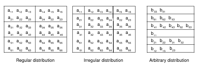 |
A distribution can also be specified using the DistGrid, by passing object into a Grid create call.
Any of these logically rectangular grid types can be combined through edge connections to form a mosaic. Cubed sphere and yin-yang grids are examples of mosaic grids. Note that as of v5.1.0 multi-tile grids have not yet been implemented.
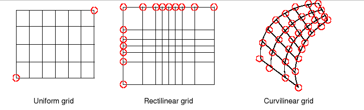 |
Each of these coordinate types can be set for each of the standard grid shapes described in section 25.1.3.
The table below shows how examples of common single Tile grids fall into this shape and coordinate taxonomy. Note that any of the grids in the table can have a regular or arbitrary distribution.
| Uniform | Rectilinear | Curvilinear | |
| Sphere | Global uniform lat-lon grid | Gaussian grid | Displaced pole grid |
| Rectangle | Regional uniform lat-lon grid | Gaussian grid section | Polar stereographic grid section |
There are two ways of specifying coordinates in ESMF. The first way is for the user to set the coordinates. The second way is to take a shortcut and have the framework generate the coordinates.
No ESMF generation routines are currently available.
See Section 25.3.9 for more description and examples of setting coordinates.
Staggering is a finite difference technique in which the values of different physical quantities are placed at different locations within a grid cell.
The ESMF Grid class supports a variety of stagger locations, including cell centers, corners, and edge centers. The default stagger location in ESMF is the cell center, and cell counts in Grid are based on this assumption. Combinations of the 2D ESMF stagger locations are sufficient to specify any of the Arakawa staggers. ESMF also supports staggering in 3D and higher dimensions. There are shortcuts for standard staggers, and interfaces through which users can create custom staggers.
As a default the ESMF Grid class provides symmetric staggering, so that cell centers are enclosed by cell perimeter (e.g. corner) stagger locations. This means the coordinate arrays for stagger locations other than the center will have an additional element of padding in order to enclose the cell center locations. However, to achieve other types of staggering, the user may alter or eliminate this padding by using the appropriate options when adding coordinates to a Grid.
In v5.1.0, only the cell center stagger location is supported for an arbitrarily distributed grid. For examples and a full description of the stagger interface see Section 25.3.9.
ESMF Grid objects must represent a wide range of grid types and use cases, some of them quite complex. As a result, multiple ways to build Grid objects are required. This section describes the stages to building Grids, the options for each stage, and typical calling sequences.
In ESMF there are two main stages to building Grids. The ESMF_GridStatus value stored within the Grid object reflects the stage the Grid has attained (see Section 25.2.2). These stages are:
The options for specifying the Grid shape are:
When creating the Grid shape and specifying the Grid coordinates, the user can either specify all required information at once, or can provide information incrementally. The call ESMF_GridCreateEmpty() builds a Grid object container that can be filled in with a subsequent call to the ESMF_GridSetCommitShapeTile() method. The ESMF_GridSetCommitShapeTile() creates the grid and sets the appropriate flag to indicate that its usable (the status equals ESMF_GRIDSTATUS_SHAPE_READY after the commit). The Grid is implicitly in a valid state after being committed.
For consistency's sake the ESMF_GridSetCommitShapeTile() call must occur on the same or a subset of the PETs as the ESMF_GridCreateEmpty() call. The ESMF_GridSetCommitShapeTile() call uses the VM for the context in which it's executed and the "empty" Grid contains no information about the VM in which it was run. If the ESMF_GridSetCommitShapeTile() call occurs in a subset of the PETs in which the ESMF_GridCreateEmpty() was executed, the Grid is created only in that subset. The grid objects outside the subset will still be "empty" and not usable.
The following table summarizes possible call sequences for building Grids.
| Create Shape |
| From shape shortcut |
| grid = ESMF_GridCreateShapeTile(...) |
| Using DistGrid with general create interface |
| distgrid = ESMF_DistGridCreate(...) |
| grid = ESMF_GridCreate(distgrid, ...) |
| Incremental |
| grid = ESMF_GridCreateEmpty(...) |
| call ESMF_GridSetCommitShapeTile(grid, ...) |
| Set Coordinates |
| Set coordinates by copy or reference |
| call ESMF_GridSetCoord(grid, ...) |
| Retrieve ESMF Array of coordinates from Grid and set values |
| call ESMF_GridGetCoord(grid, esmfArray, ...), set values |
| Retrieve local bounds and native array from Grid and set values |
| call ESMF_GridGetCoord(grid, lbound, ubound, array), set values |
DESCRIPTION:
The ESMF Grid class can exist in three states. These states are
present so that the library code can detect if a Grid has been
appropriately setup for the task at hand. The following
are the valid values of ESMF_GRIDSTATUS.
DESCRIPTION:
The ESMF Grid can contain other kinds of data besides coordinates.
This data is referred to as Grid ``items''. Some items may be used
by ESMF for calculations involving the Grid. The following
are the valid values of ESMF_GRIDITEM.
| Item Label | Type Restriction | Type Default | ESMF Uses | Controls |
| ESMF_GRIDITEM_MASK | ESMF_TYPEKIND_I4 | ESMF_TYPEKIND_I4 | YES | Masking in Regrid |
| ESMF_GRIDITEM_AREA | NONE | ESMF_TYPEKIND_R8 | NO | N/A |
| ESMF_GRIDITEM_AREAM | NONE | ESMF_TYPEKIND_R8 | NO | N/A |
| ESMF_GRIDITEM_FRAC | NONE | ESMF_TYPEKIND_R8 | NO | N/A |
DESCRIPTION:
In the ESMF Grid class, data can be located at different positions in a
Grid cell. When setting or retrieving coordinate data the stagger location is
specified to tell the Grid method from where in the cell to get the data.
Although the user may define their own custom stagger locations,
ESMF provides a set of predefined locations for ease of use. The
following are the valid predefined stagger locations.
The 2D predefined stagger locations (illustrated in figure 14) are:
The 3D predefined stagger locations (illustrated in figure 15) are:
This section describes the use of the ESMF Grid class. It first discusses the more user friendly shape specific interface to the Grid. During this discussion it covers creation and options, adding stagger locations, coordinate data access, and other grid functionality. After this initial phase the document discusses the more advanced options which the user can employ should they need more customized interaction with the Grid class.
The method ESMF_GridCreateShapeTile() is a shortcut for building single tile logically rectangular Grids up to three dimensions. It is partially implemented. The user can specify Grid size, dimension and distribution, but cannot specify tile edge connectivities yet. The default is that Grid edges are not connected. Once completed, this method will enable users to create many common grid shapes, including rectangle, bipole sphere, and tripole sphere.
In v5.1.0, the ESMF_GridCreateShapeTile() method supports all three types of distributions described in Section 25.1.4: regular, irregular and arbitrary.
The ESMF Grid is cell based and so for all distribution options the methods take as input the number of cells to describe the total index space and the number of cells to specify distribution.
To create a Grid with a regular distribution the user specifies the global maximum and minimum ranges of the Grid cell index space (maxIndex and minIndex), and the number of pieces in which to partition each dimension (via a regDecomp argument). ESMF then divides the index space as evenly as possible into the specified number of pieces. If there are cells left over then they are distributed one per DE starting from the first DE until they are gone.
If minIndex is not specified, then the bottom of the Grid cell index range is assumed to be (1,1,...,1). If regDecomp is not specified, then by default ESMF creates a distribution that partitions the grid cells in the first dimension (e.g. NPx1x1...1) as evenly as possible by the number of processors NP. The remaining dimensions are not partitioned. The dimension of the Grid is the size of maxIndex. The following is an example of creating a 10x20x30 3D grid where the first dimensions is broken into 2 pieces, the second is broken into 4 pieces, and the third is "distributed" across only one processor.
grid3D=ESMF_GridCreateShapeTile(regDecomp=(/2,4,1/), maxIndex=(/10,20,30/), &
rc=rc)
Irregular distribution requires the user to specify the exact number of Grid cells per DE in each dimension. In the ESMF_GridCreateShapeTile() call the countsPerDEDim1, countsPerDim2, and countsPerDim3 arguments are used to specify a rectangular distribution containing size(countsPerDEDim1) by size(countsPerDEDim2) by size(countsPerDEDim3) DEs. The entries in each of these arrays specify the number of grid cells per DE in that dimension. The dimension of the grid is determined by the presence of countsPerDEDim3. If it's present the Grid will be 3D. If just countsPerDEDim1 and countsPerDEDim2 are specified the Grid will be 2D.
The following call illustrates the creation of a 10x20 two dimensional rectangular Grid distributed across six DEs that are arranged 2x3. In the first dimension there are 3 grid cells on the first DE and 7 cells on the second DE. The second dimension has 3 DEs with 11,2, and 7 cells, respectively.
grid2D=ESMF_GridCreateShapeTile(countsPerDEDim1=(/3,7/), &
countsPerDEDim2=(/11,2,7/), rc=rc)
To add a distributed third dimension of size 30, broken up into two groups of 15, the above call would be altered as follows.
grid3d=ESMF_GridCreateShapeTile(countsPerDEDim1=(/3,7/), &
countsPerDEDim2=(/11,2,7/), countsPerDEDim3=(/15,15/), rc=rc)
To make a third dimension distributed across only 1 DE, then countsPerDEDim3 in the call should only have a single term.
grid3D=ESMF_GridCreateShapeTile(countsPerDEDim1=(/3,7/), &
countsPerDEDim2=(/11,2,7/), countsPerDEDim3=(/30/), rc=rc)
The petMap parameter may be used to specify on to which specific PETs the DEs in the Grid are assigned. Note that this parameter is only available for the regular and irregular distribution types. The petMap array is a 3D array, for a 3D Grid each of its dimensions correspond to a Grid dimension. If the Grid is 2D, then the first two dimensions correspond to Grid dimensions and the last dimension should be of size 1. The size of each petMap dimension is the number of DE's along that dimension in the Grid. For a regular Grid, the size is equal to the number in regDecomp (i.e. size(petMap,d)=regDecomp(d) for all dimensions d in the Grid). For an irregular Grid the size is equal to the number of items in the corresponding countsPerDEDim variable (i.e. size(petMap,d)=size(countsPerDEDimd) for all dimensions d in the Grid).
The petMap parameter may be used to specify on to which specific PETs Each entry in petMap specifies to which PET the corresponding DE should be assigned. For example, petMap(3,2)=4 tells the Grid create call to put the DE located at column 3 row 2 on PET 4.
The petMap parameter may be used to specify on to which specific PETs The following example demonstrates how to specify the PET to DE association for an ESMF_GridCreateShapeTile() call.
! allocate memory for petMap
allocate( petMap(2,2,1) )
! Set petMap
petMap(:,1,1) = (/3,2/) ! DE (1,1,1) on PET 3 and DE (2,1,1) on PET 2
petMap(:,2,1) = (/1,0/) ! DE (1,2,1) on PET 1 and DE (2,2,1) on PET 0
! Let the 3D grid be be distributed only in the first two dimensions.
grid2D=ESMF_GridCreateShapeTile(countsPerDEDim1=(/3,7/), &
countsPerDEDim2=(/7,6/), petMap=petMap, rc=rc)
To create an grid with arbitrary distribution, the user specifies the global minimum and maximum ranges of the index space with the arguments minIndex and maxIndex, the total number of cells and their index space locations residing on the local PET through a localArbIndexCount and a localArbIndex argument. localArbIndex is a 2D array with size (localArbIndexCount, n) where n is the total number dimensions distributed arbitrarily. Again, if minIndex is not specified, then the bottom of the index range is assumed to be (1,1,...). The dimension of the Grid is equal to the size of maxIndex. If n (number of arbitrarily distributed dimension) is less than the grid dimension, an optional argument distDim is used to specify which of the grid dimension is arbitrarily distributed. If not given, the first n dimensions are assumed to be distributed.
The following example creates a 2D Grid of dimensions 5x5, and places the diagonal elements (i.e. indices (i,i) where i goes from 1 to 5) on the local PET. The remaining PETs would individually declare the remainder of the Grid locations.
! allocate memory for localArbIndex
allocate( localArbIndex(5,2) )
! Set local indices
localArbIndex(1,:)=(/1,1/)
localArbIndex(2,:)=(/2,2/)
localArbIndex(3,:)=(/3,3/)
localArbIndex(4,:)=(/4,4/)
localArbIndex(5,:)=(/5,5/)
! Create a 2D Arbitrarily distributed Grid
grid2D=ESMF_GridCreateShapeTile(maxIndex=(/5,5/), &
arbIndexList=localArbIndex, arbIndexCount=5, rc=rc)
To create a 3D Grid of dimensions 5x6x5 with the first and the third dimensions distributed arbitrarily, distDim is used.
! Create a 3D Grid with the 1st and 3rd dimension arbitrarily distributed
grid3D=ESMF_GridCreateShapeTile(maxIndex=(/5,6,5/), &
arbIndexList=localArbIndex, arbIndexCount=5, &
distDim=(/1,3/), rc=rc)
The following is an example of creating a simple rectilinear grid and loading in a set of coordinates. It illustrates a straightforward use of the ESMF_GridCreateShapeTile() call described in the previous section. This code creates a 10x20 2D grid with uniformly spaced coordinates varying from (10,10) to (100,200). The grid is partitioned using a regular distribution. The first dimension is divided into two pieces, and the second dimension is divided into 3. This example assumes that the code is being run with a 1-1 mapping between PETs and DEs because we are only accessing the first DE on each PET (localDE=0). Because we have 6 DEs (2x3), this example would only work when run on 6 PETs. The Grid is created with global indices. After Grid creation the local bounds and native Fortran arrays are retrieved and the coordinates are set by the user.
!-------------------------------------------------------------------
! Create the Grid: Allocate space for the Grid object, define the
! topology and distribution of the Grid, and specify that it
! will have global indices. Note that aperiodic bounds are
! specified by default - if periodic bounds were desired they
! would need to be specified using an additional gridConn argument
! (which isn't implemented yet). In this call the minIndex hasn't
! been set, so it defaults to (1,1,...). The default is to
! divide the index range as equally as possible among the DEs
! specified in regDecomp. This behavior can be changed by
! specifying decompFlag.
!-------------------------------------------------------------------
grid2D=ESMF_GridCreateShapeTile( &
! Define a regular distribution
maxIndex=(/10,20/), & ! define index space
regDecomp=(/2,3/), & ! define how to divide among DEs
! Specify mapping of coords dim to Grid dim
coordDep1=(/1/), & ! 1st coord is 1D and depends on 1st Grid dim
coordDep2=(/2/), & ! 2nd coord is 1D and depends on 2nd Grid dim
indexflag=ESMF_INDEX_GLOBAL, &
rc=rc)
!-------------------------------------------------------------------
! Allocate coordinate storage and associate it with the center
! stagger location. Since no coordinate values are specified in
! this call no coordinate values are set yet.
!-------------------------------------------------------------------
call ESMF_GridAddCoord(grid2D, &
staggerloc=ESMF_STAGGERLOC_CENTER, rc=rc)
!-------------------------------------------------------------------
! Get the pointer to the first coordinate array and the bounds
! of its global indices on the local DE.
!-------------------------------------------------------------------
call ESMF_GridGetCoord(grid2D, coordDim=1, localDE=0, &
staggerloc=ESMF_STAGGERLOC_CENTER, &
computationalLBound=lbnd, computationalUBound=ubnd, &
farrayPtr=coordX, rc=rc)
!-------------------------------------------------------------------
! Calculate and set coordinates in the first dimension [10-100].
!-------------------------------------------------------------------
do i=lbnd(1),ubnd(1)
coordX(i) = i*10.0
enddo
!-------------------------------------------------------------------
! Get the pointer to the second coordinate array and the bounds of
! its global indices on the local DE.
!-------------------------------------------------------------------
call ESMF_GridGetCoord(grid2D, coordDim=2, localDE=0, &
staggerloc=ESMF_STAGGERLOC_CENTER, &
computationalLBound=lbnd, computationalUBound=ubnd, &
farrayPtr=coordY, rc=rc)
!-------------------------------------------------------------------
! Calculate and set coordinates in the second dimension [10-200]
!-------------------------------------------------------------------
do j=lbnd(1),ubnd(1)
coordY(j) = j*10.0
enddo
The remaining examples in this section will use the irregular distribution because of its greater generality. To create code similar to these, but using a regular distribution, replace the countsPerDEDim arguments in the Grid create with the appropriate maxIndex and regDecomp arguments.
This example serves as an illustration of the difference between using a regular and irregular distribution. It repeats the previous example except using an irregular distribution to give the user more control over how the cells are divided between the DEs. As before, this code creates a 10x20 2D Grid with uniformly spaced coordinates varying from (10,10) to (100,200). In this example, the Grid is partitioned using an irregular distribution. The first dimension is divided into two pieces, the first with 3 Grid cells per DE and the second with 7 Grid cells per DE. In the second dimension, the Grid is divided into 3 pieces, with 11, 2, and 7 cells per DE respectively. This example assumes that the code is being run with a 1-1 mapping between PETs and DEs because we are only accessing the first DE on each PET (localDE=0). Because we have 6 DEs (2x3), this example would only work when run on 6 PETs. The Grid is created with global indices. After Grid creation the local bounds and native Fortran arrays are retrieved and the coordinates are set by the user.
!-------------------------------------------------------------------
! Create the Grid: Allocate space for the Grid object, define the
! topology and distribution of the Grid, and specify that it
! will have global coordinates. Note that aperiodic bounds are
! specified by default - if periodic bounds were desired they
! would need to be specified using an additional gridConn argument
! (which isn't implemented yet). In this call the minIndex hasn't
! been set, so it defaults to (1,1,...).
!-------------------------------------------------------------------
grid2D=ESMF_GridCreateShapeTile( &
! Define an irregular distribution
countsPerDEDim1=(/3,7/), &
countsPerDEDim2=(/11,2,7/), &
! Specify mapping of coords dim to Grid dim
coordDep1=(/1/), & ! 1st coord is 1D and depends on 1st Grid dim
coordDep2=(/2/), & ! 2nd coord is 1D and depends on 2nd Grid dim
indexflag=ESMF_INDEX_GLOBAL, &
rc=rc)
!-------------------------------------------------------------------
! Allocate coordinate storage and associate it with the center
! stagger location. Since no coordinate values are specified in
! this call no coordinate values are set yet.
!-------------------------------------------------------------------
call ESMF_GridAddCoord(grid2D, &
staggerloc=ESMF_STAGGERLOC_CENTER, rc=rc)
!-------------------------------------------------------------------
! Get the pointer to the first coordinate array and the bounds
! of its global indices on the local DE.
!-------------------------------------------------------------------
call ESMF_GridGetCoord(grid2D, coordDim=1, localDE=0, &
staggerloc=ESMF_STAGGERLOC_CENTER, &
computationalLBound=lbnd, computationalUBound=ubnd, &
farrayPtr=coordX, rc=rc)
!-------------------------------------------------------------------
! Calculate and set coordinates in the first dimension [10-100].
!-------------------------------------------------------------------
do i=lbnd(1),ubnd(1)
coordX(i) = i*10.0
enddo
!-------------------------------------------------------------------
! Get the pointer to the second coordinate array and the bounds of
! its global indices on the local DE.
!-------------------------------------------------------------------
call ESMF_GridGetCoord(grid2D, coordDim=2, localDE=0, &
staggerloc=ESMF_STAGGERLOC_CENTER, &
computationalLBound=lbnd, computationalUBound=ubnd, &
farrayPtr=coordY, rc=rc)
!-------------------------------------------------------------------
! Calculate and set coordinates in the second dimension [10-200]
!-------------------------------------------------------------------
do j=lbnd(1),ubnd(1)
coordY(j) = j*10.0
enddo
The following is an example of creating a simple curvilinear Grid and loading in a set of coordinates. It creates a 10x20 2D Grid where the coordinates vary along every dimension. The Grid is partitioned using an irregular distribution. The first dimension is divided into two pieces, the first with 3 Grid cells per DE and the second with 7 Grid cells per DE. In the second dimension, the Grid is divided into 3 pieces, with 11, 2, and 7 cells per DE respectively. This example assumes that the code is being run with a 1-1 mapping between PETs and DEs because we are only accessing the first DE on each PET (localDE=0). Because we have 6 DEs (2x3), this example would only work when run on 6 PETs. The Grid is created with global indices. After Grid creation the local bounds and native Fortran arrays are retrieved and the coordinates are set by the user.
!-------------------------------------------------------------------
! Create the Grid: Allocate space for the Grid object, define the
! distribution of the Grid, and specify that it
! will have global indices. Note that aperiodic bounds are
! specified by default - if periodic bounds were desired they
! would need to be specified using an additional gridConn argument
! (which isn't implemented yet). In this call the minIndex hasn't
! been set, so it defaults to (1,1,...).
!-------------------------------------------------------------------
grid2D=ESMF_GridCreateShapeTile( &
! Define an irregular distribution
countsPerDEDim1=(/3,7/), &
countsPerDEDim2=(/11,2,7/), &
! Specify mapping of coords dim to Grid dim
coordDep1=(/1,2/), & ! 1st coord is 2D and depends on both Grid dim
coordDep2=(/1,2/), & ! 2nd coord is 1D and depends on both Grid dim
indexflag=ESMF_INDEX_GLOBAL, &
rc=rc)
!-------------------------------------------------------------------
! Allocate coordinate storage and associate it with the center
! stagger location. Since no coordinate values are specified in
! this call no coordinate values are set yet.
!-------------------------------------------------------------------
call ESMF_GridAddCoord(grid2D, &
staggerloc=ESMF_STAGGERLOC_CENTER, rc=rc)
!-------------------------------------------------------------------
! Get the pointer to the first coordinate array and the bounds
! of its global indices on the local DE.
!-------------------------------------------------------------------
call ESMF_GridGetCoord(grid2D, coordDim=1, localDE=0, &
staggerloc=ESMF_STAGGERLOC_CENTER, &
computationalLBound=lbnd, computationalUBound=ubnd, &
farrayPtr=coordX2D, rc=rc)
!-------------------------------------------------------------------
! Calculate and set coordinates in the first dimension [10-100].
!-------------------------------------------------------------------
do j=lbnd(2),ubnd(2)
do i=lbnd(1),ubnd(1)
coordX2D(i,j) = i+j
enddo
enddo
!-------------------------------------------------------------------
! Get the pointer to the second coordinate array and the bounds of
! its global indices on the local DE.
!-------------------------------------------------------------------
call ESMF_GridGetCoord(grid2D, coordDim=2, localDE=0, &
staggerloc=ESMF_STAGGERLOC_CENTER, &
computationalLBound=lbnd, computationalUBound=ubnd, &
farrayPtr=coordY2D, rc=rc)
!-------------------------------------------------------------------
! Calculate and set coordinates in the second dimension [10-200]
!-------------------------------------------------------------------
do j=lbnd(2),ubnd(2)
do i=lbnd(1),ubnd(1)
coordY2D(i,j) = j-i/100.0
enddo
enddo
This example demonstrates how a user can build a rectilinear horizontal Grid with a non-distributed vertical dimension. The Grid contains both the center and corner stagger locations (i.e. Arakawa B-Grid). In contrast to the previous examples, this example doesn't assume that the code is being run with a 1-1 mapping between PETs and DEs. It should work when run on any number of PETs.
!-------------------------------------------------------------------
! Create the Grid: Allocate space for the Grid object. The
! Grid is defined to be 180 Grid cells in the first dimension
! (e.g. longitude), 90 Grid cells in the second dimension
! (e.g. latitude), and 40 Grid cells in the third dimension
! (e.g. height). The first dimension is decomposed over 4 DEs,
! the second over 3 DEs, and the third is not distributed.
! The connectivities in each dimension default to aperiodic
! since they are not yet implemented. In this call
! the minIndex hasn't been set, so it defaults to (1,1,...).
!-------------------------------------------------------------------
grid3D=ESMF_GridCreateShapeTile( &
! Define an irregular distribution
countsPerDEDim1=(/45,75,40,20/), &
countsPerDEDim2=(/30,40,20/), &
countsPerDEDim3=(/40/), &
! Specify mapping of coords dim to Grid dim
coordDep1=(/1/), & ! 1st coord is 1D and depends on 1st Grid dim
coordDep2=(/2/), & ! 2nd coord is 1D and depends on 2nd Grid dim
coordDep3=(/3/), & ! 3rd coord is 1D and depends on 3rd Grid dim
indexflag=ESMF_INDEX_GLOBAL, & ! Use global indices
rc=rc)
!-------------------------------------------------------------------
! Allocate coordinate storage for both center and corner stagger
! locations. Since no coordinate values are specified in this
! call no coordinate values are set yet.
!-------------------------------------------------------------------
call ESMF_GridAddCoord(grid3D, &
staggerloc=ESMF_STAGGERLOC_CENTER_VCENTER, rc=rc)
call ESMF_GridAddCoord(grid3D, &
staggerloc=ESMF_STAGGERLOC_CORNER_VCENTER, rc=rc)
!-------------------------------------------------------------------
! Get the number of DEs on this PET, so that the program
! can loop over them when accessing data.
!-------------------------------------------------------------------
call ESMF_GridGet(grid3D, localDECount=localDECount, rc=rc)
!-------------------------------------------------------------------
! Loop over each localDE when accessing data
!-------------------------------------------------------------------
do lDE=0,localDECount-1
!------------------------------------------------------------------
! Fill in the coordinates for the corner stagger location first.
!------------------------------------------------------------------
!----------------------------------------------------------------
! Get the local bounds of the global indexing for the first
! coordinate array on the local DE. If the number of PETs
! is less than the total number of DEs then the rest of this
! example would be in a loop over the local DEs. Also get the
! pointer to the first coordinate array.
!----------------------------------------------------------------
call ESMF_GridGetCoord(grid3D, coordDim=1, localDE=lDE, &
staggerLoc=ESMF_STAGGERLOC_CORNER_VCENTER, &
computationalLBound=lbnd_corner, &
computationalUBound=ubnd_corner, &
farrayPtr=cornerX, rc=rc)
!----------------------------------------------------------------
! Calculate and set coordinates in the first dimension.
!----------------------------------------------------------------
do i=lbnd_corner(1),ubnd_corner(1)
cornerX(i) = (i-1)*(360.0/180.0)
enddo
!----------------------------------------------------------------
! Get the local bounds of the global indexing for the second
! coordinate array on the local DE. Also get the pointer to the
! second coordinate array.
!----------------------------------------------------------------
call ESMF_GridGetCoord(grid3D, coordDim=2, localDE=lDE, &
staggerLoc=ESMF_STAGGERLOC_CORNER_VCENTER, &
computationalLBound=lbnd_corner, &
computationalUBound=ubnd_corner, &
farrayPtr=cornerY, rc=rc)
!----------------------------------------------------------------
! Calculate and set coordinates in the second dimension.
!----------------------------------------------------------------
do j=lbnd_corner(1),ubnd_corner(1)
cornerY(j) = (j-1)*(180.0/90.0)
enddo
!----------------------------------------------------------------
! Get the local bounds of the global indexing for the third
! coordinate array on the local DE, and the pointer to the array.
!----------------------------------------------------------------
call ESMF_GridGetCoord(grid3D, coordDim=3, localDE=lDE, &
staggerloc=ESMF_STAGGERLOC_CENTER_VCENTER, &
computationalLBound=lbnd, computationalUBound=ubnd,&
farrayPtr=cornerZ, rc=rc)
!----------------------------------------------------------------
! Calculate and set the vertical coordinates
!----------------------------------------------------------------
do k=lbnd(1),ubnd(1)
cornerZ(k) = 4000.0*( (1./39.)*(k-1) )**2
enddo
!------------------------------------------------------------------
! Now fill the coordinates for the center stagger location with
! the average of the corner coordinate location values.
!------------------------------------------------------------------
!----------------------------------------------------------------
! Get the local bounds of the global indexing for the first
! coordinate array on the local DE, and the pointer to the array.
!----------------------------------------------------------------
call ESMF_GridGetCoord(grid3D, coordDim=1, localDE=lDE, &
staggerloc=ESMF_STAGGERLOC_CENTER_VCENTER, &
computationalLBound=lbnd, computationalUBound=ubnd, &
farrayPtr=centerX, rc=rc)
!----------------------------------------------------------------
! Calculate and set coordinates in the first dimension.
!----------------------------------------------------------------
do i=lbnd(1),ubnd(1)
centerX(i) = 0.5*(i-1 + i)*(360.0/180.0)
enddo
!----------------------------------------------------------------
! Get the local bounds of the global indexing for the second
! coordinate array on the local DE, and the pointer to the array.
!----------------------------------------------------------------
call ESMF_GridGetCoord(grid3D, coordDim=2, localDE=lDE, &
staggerloc=ESMF_STAGGERLOC_CENTER_VCENTER, &
computationalLBound=lbnd, computationalUBound=ubnd, &
farrayPtr=centerY, rc=rc)
!----------------------------------------------------------------
! Calculate and set coordinates in the second dimension.
!----------------------------------------------------------------
do j=lbnd(1),ubnd(1)
centerY(j) = 0.5*(j-1 + j)*(180.0/90.0)
enddo
!----------------------------------------------------------------
! Get the local bounds of the global indexing for the third
! coordinate array on the local DE, and the pointer to the array.
!----------------------------------------------------------------
call ESMF_GridGetCoord(grid3D, coordDim=3, localDE=lDE, &
staggerloc=ESMF_STAGGERLOC_CENTER_VCENTER, &
computationalLBound=lbnd, computationalUBound=ubnd,&
farrayPtr=centerZ, rc=rc)
!----------------------------------------------------------------
! Calculate and set the vertical coordinates
!----------------------------------------------------------------
do k=lbnd(1),ubnd(1)
centerZ(k) = 4000.0*( (1./39.)*(k-1) )**2
enddo
!-------------------------------------------------------------------
! End of loop over DEs
!-------------------------------------------------------------------
enddo
There are more restrictions in defining an arbitrarily distributed grid. First, there is always one DE per PET. Secondly, only local index (ESMF_INDEX_LOCAL) is supported. Third, only one stagger location, i.e. ESMF_STAGGERLOC_CENTER is allowed and last there is no extra paddings on the edge of the grid.
This example demonstrates how a user can build a 3D grid with its rectilinear horizontal Grid distributed arbitrarily and a non-distributed vertical dimension.
!-------------------------------------------------------------------
! Set up the local index array: Assuming the grid is 360x180x10. First
! calculate the localArbIndexCount and localArbIndex array for each PET
! based on the total number of PETS. The cells are evenly distributed in
! all the PETs. If the total number of cells are not divisible by the
! total PETs, the remaining cells are assigned to the last PET. The
! cells are card dealed to each PET in y dimension first,
! i.e. (1,1) -> PET 0, (1,2)-> PET 1, (1,3)-> PET 2, and so forth.
!-------------------------------------------------------------------
xdim = 360
ydim = 180
zdim = 10
localArbIndexCount = (xdim*ydim)/petCount
remain = (xdim*ydim)-localArbIndexCount*petCount
if (localPet == petCount-1) localArbIndexCount = localArbIndexCount+remain
allocate(localArbIndex(localArbIndexCount,2))
ind = localPet
do i=1, localArbIndexCount
localArbIndex(i,1)=mod(ind,ydim)+1
localArbIndex(i,2)=ind/ydim + 1
ind = ind + petCount
enddo
if (localPet == petCount-1) then
ind = xdim*ydim-remain+1
do i=localArbIndexCount-remain+1,localArbIndexCount
localArbIndex(i,1)=mod(ind,ydim)+1
localArbIndex(i,2)=ind/ydim+1
ind = ind + 1
enddo
endif
!-------------------------------------------------------------------
! Create the Grid: Allocate space for the Grid object.
! the minIndex hasn't been set, so it defaults to (1,1,...). The
! default coordDep1 and coordDep2 are (/ESMF_GRID_ARBDIM/) where
! ESMF_GRID_ARBDIM represents the collapsed dimension for the
! arbitrarily distributed grid dimensions. For the undistributed
! grid dimension, the default value for coordDep3 is (/3/). The
! default values for coordDepX in the arbitrary distribution are
! different from the non-arbitrary distributions.
!-------------------------------------------------------------------
grid3D=ESMF_GridCreateShapeTile( &
maxIndex = (/xdim, ydim, zdim/), &
arbIndexList = localArbIndex, &
arbIndexCount = localArbIndexCount, &
rc=rc)
!-------------------------------------------------------------------
! Allocate coordinate storage for the center stagger location, the
! only stagger location supported for the arbitrary distribution.
!-------------------------------------------------------------------
call ESMF_GridAddCoord(grid3D, &
staggerloc=ESMF_STAGGERLOC_CENTER_VCENTER, rc=rc)
!------------------------------------------------------------------
! Fill in the coordinates for the center stagger location. There is
! always one DE per PET, so localDE is always 0
!------------------------------------------------------------------
call ESMF_GridGetCoord(grid3D, coordDim=1, localDE=0, &
staggerLoc=ESMF_STAGGERLOC_CENTER, &
computationalLBound=lbnd, &
computationalUBound=ubnd, &
farrayPtr=centerX, rc=rc)
!----------------------------------------------------------------
! Calculate and set coordinates in the first dimension.
!----------------------------------------------------------------
do i=lbnd(1),ubnd(1)
centerX(i) = (localArbIndex(i,1)-0.5)*(360.0/xdim)
enddo
!----------------------------------------------------------------
! Get the local bounds of the global indexing for the second
! coordinate array on the local DE, and the pointer to the array.
!----------------------------------------------------------------
call ESMF_GridGetCoord(grid3D, coordDim=2, localDE=0, &
staggerloc=ESMF_STAGGERLOC_CENTER, &
computationalLBound=lbnd, computationalUBound=ubnd, &
farrayPtr=centerY, rc=rc)
!----------------------------------------------------------------
! Calculate and set coordinates in the second dimension.
!----------------------------------------------------------------
do j=lbnd(1),ubnd(1)
centerY(j) = (localArbIndex(j,2)-0.5)*(180.0/ydim)-90.0
enddo
!----------------------------------------------------------------
! Get the local bounds of the global indexing for the third
! coordinate array on the local DE, and the pointer to the array.
!----------------------------------------------------------------
call ESMF_GridGetCoord(grid3D, coordDim=3, localDE=0, &
staggerloc=ESMF_STAGGERLOC_CENTER, &
computationalLBound=lbnd, computationalUBound=ubnd,&
farrayPtr=centerZ, rc=rc)
!----------------------------------------------------------------
! Calculate and set the vertical coordinates
!----------------------------------------------------------------
do k=lbnd(1),ubnd(1)
centerZ(k) = 4000.0*( (1./zdim)*(k-1))**2
enddo
ESMF supports the creation of a 2D curvilinear Grid using the coordinates defined in a SCRIP format Grid file [10]. The grid contained in the file must be a 2D logically rectangular grid with grid_rank in the file set to 2. The center coordinates variables grid_center_lat and grid_center_lon in the file are placed in the ESMF_STAGGERLOC_CENTER location. If the parameter addCornerStagger in the ESMF_GridCreate call is set to .true., then the variables grid_corner_lat and grid_corner_lon in the file are used to set the ESMF_STAGGERLOC_CORNER coordinates, otherwise they are ignored. The values in the grid_imask variable in the file are used to set the ESMF_GRIDITEM_MASK in the Grid.
The following example code shows you how to create a 2D Grid with both center and corner coordinates using a SCRIP file and a row only regular distribution:
grid2D = ESMF_GridCreate(filename="data/T42_grid.nc", &
regDecomp=(/PetCount,1/), addCornerStagger=.true., rc=rc)
Where T42_grid.nc is a 2D global grid of size (128x64) and the resulting Grid is distributed by partitioning the rows evenly over all the PETs.
ESMF Grids can be created incrementally. To do this, the user first calls ESMF_GridCreateEmpty() to allocate the shell of a Grid. Next, we use the ESMF_GridSetCommitShapeTile() call that fills in the Grid and does an internal commit to make it usable. For consistency's sake the ESMF_GridSetCommitShapeTile() call must occur on the same or a subset of the PETs as the ESMF_GridCreateEmpty() call. The ESMF_GridSetCommitShapeTile() call uses the VM for the context in which it's executed and the "empty" Grid contains no information about the VM in which its create was run. This means that if the ESMF_GridSetCommitShapeTile() call occurs in a subset of the PETs in which the ESMF_GridCreateEmpty() was executed that the Grid is created only in that subset. Inside the subset the Grid will be fine, but outside the subset the Grid objects will still be "empty" and not usable. The following example uses the incremental technique to create a rectangular 10x20 Grid with coordinates at the center and corner stagger locations.
!---------------------------------------------------------------------------
! IN THE PARENT COMPONENT:
! Create an empty Grid in the parent component for use in a child component.
! The parent may be defined on more PETs than the child component.
! The child's [vm or pet list] is passed into the create call so that
! the Grid is defined on the appropriate subset of the parent's PETs.
!---------------------------------------------------------------------------
grid2D=ESMF_GridCreateEmpty(rc=rc)
!---------------------------------------------------------------------------
! IN THE CHILD COMPONENT:
! Set the Grid topology. Here we define an irregularly distributed
! rectangular Grid.
!---------------------------------------------------------------------------
call ESMF_GridSetCommitShapeTile(grid2D, &
countsPerDEDim1=(/6,4/), &
countsPerDEDim2=(/10,3,7/), rc=rc)
!---------------------------------------------------------------------------
! Add Grid coordinates at the cell center location.
!---------------------------------------------------------------------------
call ESMF_GridAddCoord(grid2D, staggerLoc=ESMF_STAGGERLOC_CENTER, rc=rc)
!---------------------------------------------------------------------------
! Add Grid coordinates at the corner stagger location.
!---------------------------------------------------------------------------
call ESMF_GridAddCoord(grid2D, staggerLoc=ESMF_STAGGERLOC_CORNER, rc=rc)
A useful finite difference technique is to place different physical quantities at different locations within a grid cell. This staggering of the physical variables on the mesh is introduced so that the difference of a field is naturally defined at the location of another variable. This method was first formalized by Mesinger and Arakawa (1976).
To support the staggering of variables, the Grid provides the idea of stagger locations. Stagger locations refer to the places in a Grid cell that can contain coordinates or other data and once a Grid is associated with a Field object, field data. Typically Grid data can be located at the cell center, at the cell corners, or at the cell faces, in 2D, 3D, and higher dimensions. (Note that any Arakawa stagger can be constructed of a set of Grid stagger locations.) There are predefined stagger locations (see Section 25.2.4), or, should the user wish to specify their own, there is also a set of methods for generating custom locations (See Section 25.3.21). Users can put Grid data (e.g. coordinates) at multiple stagger locations in a Grid. In addition, the user can create a Field at any of the stagger locations in a Grid.
By default the Grid data array at the center stagger location starts at the bottom index of the Grid (default (1,1..,1)) and extends up to the maximum cell index in the Grid (e.g. given by the maxIndex argument). Other stagger locations also start at the bottom index of the Grid, however, they can extend to +1 element beyond the center in some dimensions to allow for the extra space to surround the center elements. See Section 25.3.21 for a description of this extra space and how to adjust if it necessary. There are ESMF_GridGet subroutines (e.g. ESMF_GridGetCoord() or ESMF_GridGetItem()) which can be used to retrieve the stagger bounds for the piece of Grid data on a particular DE.
The primary type of data the Grid is resposible for storing is coordinates. The coordinate values in a Grid can be employed by the user in calculations or to describe the geometry of a Field. The Grid coordinate values are also used by ESMF_FieldRegridStore() when calculating the interpolation matrix between two Fields. The user can allocate coordinate arrays without setting coordinate values using the ESMF_GridAddCoord() call. (See Section 25.3.12 for a discussion of setting/getting coordinate values.) When adding or accessing coordinate data, the stagger location is specified to tell the Grid method where in the cell to get the data. The different stagger locations may also have slightly different index ranges and sizes. Please see Section 25.3.9 for a discussion of Grid stagger locations.
The following example adds coordinate storage to the corner stagger location in a Grid using one of the predefined stagger locations.
call ESMF_GridAddCoord(grid2D, staggerLoc=ESMF_STAGGERLOC_CORNER, rc=rc)
Note only the center stagger location ESMF_STAGGERLOC_CENTER is supported in an arbitrarily distributed Grid.
To specify how the coordinate arrays are mapped to the index dimensions the arguments coordDep1, coordDep2, and coordDep3 are used, each of which is a Fortran array. The values of the elements in a coordDep array specify which index dimension the corresponding coordinate dimension maps to. For example, coordDep1=(/1,2/) means that the first dimension of coordinate 1 maps to index dimension 1 and the second maps to index dimension 2. For a grid with non-arbitrary distribution, the default values for coordDep1, coordDep2 and coordDep3 are /1,2..,gridDimCount/. This default thus specifies a curvilinear grid.
The following call demonstrates the creation of a 10x20 2D rectilinear grid where the first coordinate component is mapped to the second index dimension (i.e. is of size 20) and the second coordinate component is mapped to the first index dimension (i.e. is of size 10).
grid2D=ESMF_GridCreateShapeTile(countsPerDEDim1=(/5,5/), &
countsPerDEDim2=(/7,7,6/), &
coordDep1=(/2/), &
coordDep2=(/1/), rc=rc)
The following call demonstrates the creation of a 10x20x30 2D plus 1 curvilinear grid where coordinate component 1 and 2 are still 10x20, but coordinate component 3 is mapped just to the third index dimension.
grid2D=ESMF_GridCreateShapeTile(countsPerDEDim1=(/6,4/), &
countsPerDEDim2=(/10,7,3/), countsPerDEDim3=(/30/), &
coordDep1=(/1,2/), coordDep2=(/1,2/), &
coordDep3=(/3/), rc=rc)
By default the local piece of the array on each PET starts at (1,1,..), however, the indexing for each grid coordinate array on each DE may be shifted to the global indices by using the indexflag. For example, the following call switches the grid to use global indices.
grid2D=ESMF_GridCreateShapeTile(countsPerDEDim1=(/6,4/), &
countsPerDEDim2=(/10,7,3/), indexflag=ESMF_INDEX_GLOBAL, rc=rc)
For an arbitrarily distributed grid, the default value of a coordinate array dimension is ESMF_GRID_ARBDIM if the index dimension is arbitrarily distributed and is n where n is the index dimension itself when it is not distributed. The following call is equivalent to the example in Section 25.3.6
grid3D=ESMF_GridCreateShapeTile( &
maxIndex = (/xdim, ydim, zdim/), &
arbIndexList = localArbIndex, &
arbIndexCount = localArbIndexCount, &
coordDep1 = (/ESMF_GRID_ARBDIM/), &
coordDep2 = (/ESMF_GRID_ARBDIM/), &
coordDep3 = (/3/), &
rc=rc)
The following call uses non-default coordDep1, coordDep2, and coordDep3 to create a 3D curvilinear grid with its horizontal dimensions arbitrarily distributed.
grid3D=ESMF_GridCreateShapeTile( &
maxIndex = (/xdim, ydim, zdim/), &
arbIndexList = localArbIndex, &
arbIndexCount = localArbIndexCount, &
coordDep1 = (/ESMF_GRID_ARBDIM, 3/), &
coordDep2 = (/ESMF_GRID_ARBDIM, 3/), &
coordDep3 = (/ESMF_GRID_ARBDIM, 3/), &
rc=rc)
Once a Grid has been created, the user has several options to access the Grid coordinate data. The first of these, ESMF_GridSetCoord(), enables the user to use ESMF Arrays to set data for one stagger location across the whole Grid. For example, the following sets the coordinates in the first dimension (e.g. x) for the corner stagger location to those in the ESMF Array arrayCoordX.
call ESMF_GridSetCoord(grid2D, &
staggerLoc=ESMF_STAGGERLOC_CORNER, &
coordDim=1, array=arrayCoordX, rc=rc)
The method ESMF_GridGetCoord() allows the user to obtain a reference to an ESMF Array which contains the coordinate data for a stagger location in a Grid. The user can then employ any of the standard ESMF_Array tools to operate on the data. The following copies the coordinates from the second component of the corner and puts it into the ESMF Array arrayCoordY.
call ESMF_GridGetCoord(grid2D, &
staggerLoc=ESMF_STAGGERLOC_CORNER, &
coordDim=2, &
array=arrayCoordY, rc=rc)
Alternatively, the call ESMF_GridGetCoord() gets a Fortran pointer to the coordinate data. The user can then operate on this array in the usual manner. The following call gets a reference to the Fortran array which holds the data for the second coordinate (e.g. y).
call ESMF_GridGetCoord(grid2D, coordDim=2, localDE=0, &
staggerloc=ESMF_STAGGERLOC_CORNER, farrayPtr=coordY2D, rc=rc)
The ESMF Grids contain the ability to store other kinds of data beyond coordinates. These kinds of data are referred to as "items". Although the user is free to use this data as they see fit, the user should be aware that this data may also be used by other parts of ESMF (e.g. the ESMF_GRIDITEM_MASK item is used in regridding). Please see Section 25.2.3 for a list of valid items.
Like coordinates items are also created on stagger locations. When adding or accessing item data, the stagger location is specified to tell the Grid method where in the cell to get the data. The different stagger locations may also have slightly different index ranges and sizes. Please see Section 25.3.9 for a discussion of Grid stagger locations. The user can allocate item arrays without setting item values using the ESMF_GridAddItem() call. (See Section 25.3.14 for a discussion of setting/getting item values.)
The following example adds mask item storage to the corner stagger location in a grid.
call ESMF_GridAddItem(grid2D, staggerLoc=ESMF_STAGGERLOC_CORNER, &
item=ESMF_GRIDITEM_MASK, rc=rc)
call ESMF_GridSetItem(grid2D, &
staggerLoc=ESMF_STAGGERLOC_CORNER, &
item=ESMF_GRIDITEM_MASK, array=arrayMask, rc=rc)
The method ESMF_GridGetItem() allows the user to get a reference to the Array which contains item data for a stagger location on a Grid. The user can then employ any of the standard ESMF_Array tools to operate on the data. The following gets the mask data from the corner and puts it into the ESMF Array arrayMask.
call ESMF_GridGetItem(grid2D, &
staggerLoc=ESMF_STAGGERLOC_CORNER, &
item=ESMF_GRIDITEM_MASK, &
array=arrayMask, rc=rc)
Alternatively, the call ESMF_GridGetItem() gets a Fortran pointer to the item data. The user can then operate on this array in the usual manner. The following call gets a reference to the Fortran array which holds the data for the mask data.
call ESMF_GridGetItem(grid2D, localDE=0, &
staggerloc=ESMF_STAGGERLOC_CORNER, &
item=ESMF_GRIDITEM_MASK, farrayPtr=mask2D, rc=rc)
Like an Array or a Field, the index space of each stagger location in the Grid contains an exclusive region, a computational region and a total region. Please see Section 22.2.6 for an in depth description of these regions.
The exclusive region is the index space defined by the distgrid of each stagger location of the Grid. This region is the region which is owned by the DE and is the region operated on by communication methods such as ESMF_FieldRegrid(). The exclusive region for a stagger location is based on the exclusive region defined by the DistGrid used to create the Grid. The size of the stagger exclusive region is the index space for the Grid cells, plus the stagger padding.
The default stagger padding depends on the topology of the Grid. For an unconnected dimension the stagger padding is a width of 1 on the upper side (i.e. gridEdgeUWidth=(1,1,1,1...)). For a periodic dimension there is no stagger padding. By adjusting gridEdgeLWidth and gridEdgeUWidth, the user can set the stagger padding for the whole Grid and thus the exclusive region can be adjusted at will around the index space corresponding to the cells. The user can also use staggerEdgeLWidth and staggerEdgeUWidth to adjust individual stagger location padding within the Grid's padding (Please see Section 25.3.22 for further discussion of customizing the stagger padding).
Figure 16 shows an example of a Grid exclusive region for the ESMF_STAGGERLOC_CORNER stagger with default stagger padding. This exclusive region would be for a Grid generated by either of the following calls:
grid2D=ESMF_GridCreateShapeTile(regDecomp=(/2,4/), maxIndex=(/5,15/), &
indexflag=ESMF_INDEX_GLOBAL, rc=rc)
grid2D=ESMF_GridCreateShapeTile(countsPerDEDim1=(/4,4,4,3/), &
countsPerDEDim2=(/3,2/), indexflag=ESMF_INDEX_GLOBAL, rc=rc)
Each rectangle in this diagram represents a DE and the numbers along the sides are the index values of the locations in the DE. Note that the exclusive region has one extra index location in each dimension than the number of cells because of the padding for the larger corner stagger location.
The computational region is a user setable region which can be used to distinguish a particular area for computation. The Grid doesn't currently contain functionality to let the user set the computational region so it defaults to the exclusive region, however, if the user sets an Array holding different computational bounds into the Grid then that Array's computational bounds will be used.
The total region is the outermost boundary of the memory allocated on each DE to hold the data for the stagger location on that DE. This region can be as small as the exclusive region, but may be larger to include space for halos, memory padding, etc. The total region is what is enlarged to include space for halos, and the total region must be large enough to contain the maximum halo operation on the Grid. The Grid doesn't currently contain functionality to let the user set the total region so it defaults to the exclusive region, however, if the user sets an Array holding different total bounds into the Grid then that Array's total bounds will be used.
The user can retrieve a set of bounds for each index space region described above: exclusive bounds, computational bounds, and total bounds. Note that although some of these are similar to bounds provided by ESMF_Array subroutines (see Section 22.2.6) the format here is different. The Array bounds are only for distributed dimensions and are ordered to correspond to the dimension order in the associated DistGrid. The bounds provided by the Grid are ordered according to the order of dimensions of the data in question. This means that the bounds provided should be usable "as is" to access the data.
Each of the three types of bounds refers to the maximum and minimum per dimension of the index ranges of a particular region. The paramters referring to the maximums contain a 'U' for upper. The parameters referring to the minimums contain an 'L' for lower. The bounds and associated quantities are almost always given on a per DE basis. The three types of bounds exclusiveBounds, computationalBounds, and totalBounds refer to the ranges of the exlusive region, the computational region, and the total region. Each of these bounds also has a corresponding count parameter which gives the number of items across that region (on a DE) in each dimension. (e.g. totalCount(d)=totallUBound(i)-totalLBound(i)+1). Width parameters give the spacing between two different types of region. The computationalWidth argument gives the spacing between the exclusive region and the computational region. The totalWidth argument gives the spacing between the total region and the computational region. Like the other bound information these are typically on a per DE basis, for example specifying totalLWidth=(1,1) makes the bottom of the total region one lower in each dimension than the computational region on each DE. The exceptions to the per DE rule are staggerEdgeWidth, and gridEdgeWidth which give the spacing only on the DEs along the boundary of the Grid.
All the above bound discussions only apply to the grid with non-arbitrary distributions, i.e., regular or irregular distributions. For an arbitrarily distributed grid, only center stagger location is supported and there is no padding around the grid. Thus, the exclusive bounds, the total bounds and the computational bounds are identical and staggerEdgeWidth, and gridEdgeWidth are all zeros.
When operating on coordinates the user may often wish to retrieve the bounds of the piece of coordinate data on a particular local DE. This is useful for iterating through the data to set coordinates, retrieve coordinates, or do calculations. The method ESMF_GridGetCoord allows the user to retrieve bound information for a particular coordinate array.
As described in the previous section there are three types of bounds the user can get: exclusive bounds, computational bounds, and total bounds. The bounds provided by ESMF_GridGetCoordBounds are for both distributed and undistributed dimensions and are ordered according to the order of dimensions in the coordinate. This means that the bounds provided should be usable "as is" to access data in the coordinate array. In the case of factorized coordinate Arrays where a coordinate may have a smaller dimension than its associated Grid, then the dimension of the coordinate's bounds are the dimension of the coordinate, not the Grid.
The following is an example of retrieving the bounds for localDE 0 for the first coordinate array from the corner stagger location.
call ESMF_GridGetCoordBounds(grid2D, coordDim=1, localDE=0, &
staggerLoc=ESMF_STAGGERLOC_CORNER, &
exclusiveLBound=elbnd, exclusiveUBound=eubnd, &
computationalLBound=clbnd, computationalUBound=cubnd, &
totalLBound=tlbnd, totalUBound=tubnd, rc=rc)
When operating on data stored at a particular stagger in a Grid the user may find it useful to be able to retrieve the bounds of the data on a particular local DE. This is useful for iterating through the data for computations or allocating arrays to hold the data. The method ESMF_GridGet allows the user to retrieve bound information for a particular stagger location.
As described in Section 25.3.15 there are three types of bounds the user can typically get, however, the Grid doesn't hold data at a stagger location (that is the job of the Field), and so no Array is contained there and so no total region exists, so the user may only retrieve exclusive and computational bounds from a stagger location. The bounds provided by ESMF_GridGet are ordered according to the order of dimensions in the Grid.
The following is an example of retrieving the bounds for localDE 0 from the corner stagger location.
call ESMF_GridGet(grid2D, localDE=0, &
staggerLoc=ESMF_STAGGERLOC_CORNER, &
exclusiveLBound=elbnd, exclusiveUBound=eubnd, &
computationalLBound=clbnd, computationalUBound=cubnd, rc=rc)
In addition to the per DE information that can be accessed about a stagger location there is some global information that can accessed by using ESMF_GridGet without specifying a localDE. One of the uses of this information is to create an ESMF Array to hold data for a stagger location.
The information currently available from a stagger location is the distgrid. The distgrid gives the distgrid which describes the size and distribution of the elements in the stagger location.
The following is an example of retrieving information for localDE 0 from the corner stagger location.
! Get info about staggerloc
call ESMF_GridGet(grid2D, staggerLoc=ESMF_STAGGERLOC_CORNER, &
distgrid=staggerDistgrid, &
rc=rc)
In order to create an Array to correspond to a Grid stagger location several pieces of information need to be obtained from both the Grid and the stagger location in the Grid.
The information that needs to be obtained from the Grid is the distgridToGridMap to ensure that the new Array has its dimensions are mapped correctly to the Grid. These are obtained using the ESMF_GridGet method.
The information that needs to be obtained from the stagger location is the distgrid that describes the size and distribution of the elements in the stagger location. This information can be obtained using the stagger location specific ESMF_GridGet method.
The following is an example of using information from a 2D Grid with non-arbitrary distribution to create an Array corresponding to a stagger location.
! Get info from Grid
call ESMF_GridGet(grid2D, distgridToGridMap=distgridToGridMap, rc=rc)
! Get info about staggerloc
call ESMF_GridGet(grid2D, staggerLoc=ESMF_STAGGERLOC_CORNER, &
distgrid=staggerDistgrid, &
rc=rc)
! construct ArraySpec
call ESMF_ArraySpecSet(arrayspec, rank=2, typekind=ESMF_TYPEKIND_R8, rc=rc)
! Create an Array based on info from grid
array=ESMF_ArrayCreate(arrayspec=arrayspec, &
distgrid=staggerDistgrid, distgridToArrayMap=distgridToGridMap, &
rc=rc)
Creating an Array for a Grid with arbitrary distribution is different. For a 2D Grid with both dimension arbitrarily distributed, the Array dimension is 1. For a 3D Grid with two arbitrarily distributed dimensions and one undistributed dimension, the Array dimension is 2. In general, if the Array does not have any ungridded dimension, the Array dimension should be 1 plus the number of undistributed dimensions of the Grid.
The following is an example of creating an Array for a 3D Grid with 2 arbitrarily distributed dimensions such as the one defined in Section 25.3.6.
! Get distGrid from Grid
call ESMF_GridGet(grid3D, distgrid=distgrid, rc=rc)
! construct ArraySpec
call ESMF_ArraySpecSet(arrayspec, rank=2, typekind=ESMF_TYPEKIND_R8, rc=rc)
! Create an Array based on the presence of distributed dimensions
array=ESMF_ArrayCreate(arrayspec=arrayspec,distgrid=distgrid, rc=rc)
Besides the shortcut methods for creating a Grid object such as ESMF_GridCreateShapeTile(), there is a set of methods which give the user more control over the specifics of the grid. The following describes the more general interface, using DistGrid. The basic idea is to first create an ESMF DistGrid object describing the distribution and shape of the Grid, and then to employ that to either directly create the Grid or first create Arrays and then create the Grid from those. This method gives the user maximum control over the topology and distribution of the Grid. See the DistGrid documentation in Section 29.1 for an in-depth description of its interface and use.
As an example, the following call constructs a 10x20 Grid with a lower bound of (1,2).
! Create DistGrid
distgrid2D = ESMF_DistGridCreate(minIndex=(/1,2/), maxIndex=(/11,22/), &
rc=rc)
! Create Grid
grid3D=ESMF_GridCreate(distGrid=distgrid2D, rc=rc)
To alter which dimensions are distributed, the distgridToGridMap argument can be used. The distgridToGridMap is used to set which dimensions of the Grid are mapped to the dimensions described by maxIndex. In other words, it describes how the dimensions of the underlying default DistGrid are mapped to the Grid. Each entry in distgridToGridMap contains the Grid dimension to which the cooresponding DistGrid dimension should be mapped. The following example illustrates the creation of a Grid where the largest dimension is first. To accomplish this the two dimensions are swapped.
! Create DistGrid
distgrid2D = ESMF_DistGridCreate(minIndex=(/1,2/), maxIndex=(/11,22/), &
rc=rc)
! Create Grid
grid2D=ESMF_GridCreate(distGrid=distgrid2D, distgridToGridMap=(/2,1/), &
rc=rc)
Although ESMF provides a set of predefined stagger locations (See Section 25.2.4), the user may need one outside this set. This section describes the construction of custom stagger locations.
To completely specify stagger for an arbitrary number of dimensions, we define the stagger location in terms of a set of cartesian coordinates. The cell is represented by a n-dimensional cube with sides of length 2, and the coordinate origin located at the center of the cell. The geometry of the cell is for reference purposes only, and does not literally represent the actual shape of the cell. Think of this method instead as an easy way to specify a part (e.g. center, corner, face) of a higher dimensional cell which is extensible to any number of dimensions.
To illustrate this approach, consider a 2D cell. In 2 dimensions
the cell is represented by a square. An xy axis is placed at its center, with the
positive x-axis oriented East and the positive y-axis oriented North.
The resulting coordinate for the lower left corner is at ![]() , and upper right
corner at
, and upper right
corner at ![]() .
However, because our staggers are symmetric they don't need to distinguish between
the
.
However, because our staggers are symmetric they don't need to distinguish between
the ![]() , and the
, and the ![]() , so we only need concern ourselves with the first quadrant of
this cell. We only need to use the
, so we only need concern ourselves with the first quadrant of
this cell. We only need to use the ![]() , and the
, and the ![]() , and many of the cell locations
collapse together (e.g. we only need to represent one corner). See figure 17
for an illustration of these concepts.
, and many of the cell locations
collapse together (e.g. we only need to represent one corner). See figure 17
for an illustration of these concepts.
The cell center is represented by the coordinate pair ![]() indicating the origin.
The cell corner is
indicating the origin.
The cell corner is ![]() in each direction, giving a coordinate pair of
in each direction, giving a coordinate pair of ![]() .
The edges are each
.
The edges are each ![]() in one dimension and
in one dimension and ![]() in the other indicating that
they're even with the center in one dimension and offset in the other.
in the other indicating that
they're even with the center in one dimension and offset in the other.
For three dimensions, the vertical component of the stagger location can be added by
simply adding an additional coordinate. The three dimensional generalization of the
cell center becomes ![]() and the cell corner becomes
and the cell corner becomes ![]() . The rest of
the 3D stagger locations are combinations of
. The rest of
the 3D stagger locations are combinations of ![]() offsets from the center.
offsets from the center.
To generalize this to ![]() dimensions, to represent a
dimensions, to represent a ![]() dimensional stagger
location. A set of
dimensional stagger
location. A set of ![]()
![]() and
and ![]() is used to specify for each dimension
whether a stagger location is aligned with the cell center in that dimension (
is used to specify for each dimension
whether a stagger location is aligned with the cell center in that dimension (![]() ),
or offset by
),
or offset by ![]() in that dimension (
in that dimension (![]() ). Using this scheme we can represent
any symmetric stagger location.
). Using this scheme we can represent
any symmetric stagger location.
To construct a custom stagger location in ESMF the subroutine ESMF_StaggerLocSet() is used to specify, for each dimension, whether the stagger is located at the interior (0) or on the boundary (1) of the cell. This method allows users to construct stagger locations for which there is no predefined value. In this example, it's used to set the 4D center and 4D corner locations.
! Set Center call ESMF_StaggerLocSet(staggerLoc,loc=(/0,0,0,0/),rc=rc) call ESMF_GridAddCoord(grid4D, staggerLoc=staggerLoc, rc=rc) ! Set Corner call ESMF_StaggerLocSet(staggerLoc,loc=(/1,1,1,1/),rc=rc) call ESMF_GridAddCoord(grid4D, staggerLoc=staggerLoc, rc=rc)
There is an added complication with the data (e.g. coordinates) stored at stagger locations in that they can require different amounts of storage depending on the underlying Grid type.
Consider the example 2D grid in figure 18, where the dots represent the cell corners and the ``+'' represents the cell centers. For the corners to completely enclose the cell centers (symmetric stagger), the number of corners in each dimension needs to be one greater then the number of cell centers. In the above figure, there are two rows and three columns of cell centers. To enclose the cell centers, there must be three rows and four columns of cell corners. This is true in general for Grids without periodicity or other connections. In fact, for a symmetric stagger, given that the center location requires n x m storage, the corresponding corner location requires n+1 x m+1, and the edges, depending on the side, require n+1 x m or m+1 x n. In order to add the extra storage, a new DistGrid is created at each stagger location. This Distgrid is similar to the DistGrid used to create the Grid, but has an extra set of elements added to hold the index locations for the stagger padding. By default, when the coordinate arrays are created, one extra layer of padding is added to the index space to create symmetric staggers (i.e. the center location is surrounded). The default is to add this padding on the positive side, and to only add this padding where needed (e.g. no padding for the center, padding on both dimensions for the corner, in only one dimension for the edge in 2D.) There are two ways for the user to change these defaults.
One way is to use the GridEdgeWidth or GridAlign arguments when creating a Grid. These arguments can be used to change the default padding around the Grid cell index space. This extra padding is used by default when setting the padding for a stagger location.
The gridEdgeLWidth and
gridEdgeUWidth arguments are both 1D arrays of the
same size as the Grid dimension. The entries in the arrays
give the extra offset from the outer boundary of
the grid cell index space. The following example shows the
creation of a Grid with all the extra space to hold stagger padding
on the negative side of a Grid. This is the reverse of
the default behavior. The resulting Grid will have
an exclusive region which extends from ![]() to
to
![]() , however, the cell center stagger location
will still extend from
, however, the cell center stagger location
will still extend from ![]() to
to ![]() .
.
grid2D=ESMF_GridCreateShapeTile(minIndex=(/1,1/),maxIndex=(/10,10/), &
gridEdgeLWidth=(/1,1/), gridEdgeUWidth=(/0,0/), rc=rc)
To indicate how the data in a Grid's stagger locations are aligned with the cell centers, the optional gridAlign parameter may be used. This parameter indicates which stagger elements in a cell share the same index values as the cell center. For example, in a 2D cell, it would indicate which of the four corners has the same index value as the center. To set gridAlign, the values -1,+1 are used to indicate the alignment in each dimension. This parameter is mostly informational, however, if the gridEdgeWidth parameters are not set then its value determines where the default padding is placed. If not specified, then the default is to align all staggers to the most negative, so the padding is on the positive side. The following code illustrates creating a Grid aligned to the reverse of default (with everything to the positive side). This creates a Grid identical to that created in the previous example.
grid2D=ESMF_GridCreateShapeTile(minIndex=(/1,1/),maxIndex=(/10,10/), &
gridAlign=(/1,1/), rc=rc)
The gridEdgeWidth and gridAlign arguments both allow the user to set the default padding to be used by stagger locations in a Grid. By default, stagger locations allocated in a Grid set their stagger padding based on these values. A stagger location's padding in each dimension is equal to the value of gridEdgeWidth (or the value implied by gridAlign), unless the stagger location is centered in a dimension in which case the stagger padding is 0. For example, the cell center stagger location has 0 stagger padding in all dimensions, whereas the edge stagger location lower padding is equal to gridEdgeLWidth and the upper padding is equal to gridEdgeUWidth in one dimension, but both are 0 in the other, centered, dimension. If the user wishes to set the stagger padding individually for each stagger location they may use the staggerEdgeWidth and staggerAlign arguments.
The staggerEdgeLWidth and staggerEdgeUWidth arguments are both 1D arrays of the same size as the Grid dimension. The entries in the arrays give the extra offset from the Grid cell index space for a stagger location. The following example shows the addition of two stagger locations. The corner location has no extra boundary and the center has a single layer of extra padding on the negative side and none on the positive. This is the reverse of the default behavior.
grid2D=ESMF_GridCreate(distgrid=distgrid2D, &
gridEdgeLWidth=(/1,1/), gridEdgeUWidth=(/0,0/), rc=rc)
call ESMF_GridAddCoord(grid2D, &
staggerLoc=ESMF_STAGGERLOC_CORNER, &
staggerEdgeLWidth=(/0,0/), staggerEdgeUWidth=(/0,0/), rc=rc)
call ESMF_GridAddCoord(grid2D, &
staggerLoc=ESMF_STAGGERLOC_CENTER, &
staggerEdgeLWidth=(/1,1/), staggerEdgeUWidth=(/0,0/), rc=rc)
To indicate how the data at a particular stagger location is aligned with the cell center, the optional staggerAlign parameter may be used. This parameter indicates which stagger elements in a cell share the same index values as the cell center. For example, in a 2D cell, it would indicate which of the four corners has the same index value as the center. To set staggerAlign, the values -1,+1 are used to indicate the alignment in each dimension. If a stagger location is centered in a dimension (e.g. an edge in 2D), then that dimension is ignored in the alignment. This parameter is mostly informational, however, if the staggerEdgeWidth parameters are not set then its value determines where the default padding is placed. If not specified, then the default is to align all staggers to the most negative, so the padding is on the positive side. The following code illustrates aligning the positive (northeast in 2D) corner with the center.
call ESMF_GridAddCoord(grid2D, &
staggerLoc=ESMF_STAGGERLOC_CORNER, staggerAlign=(/1,1/), rc=rc)
This example shows how to read an ESMF GridSpec Attribute Package from an XML file and use it to create a grid. The XML file contains Attribute values filled-in by the user. The standard GridSpec Attribute Package is supplied with ESMF and is defined in an XSD file, which is used to validate the XML file. See
The following XML attributes, from the file mentioned above, specifies a two dimensional, 10x20 single-tile rectilinear grid that is regularly distributed into 2 DEs in the first dimension and 3 DEs in the second dimension, for a total of 6 DEs (2x3):
<?xml version="1.0"?>
<GridSpec>
<Mosaic>
<attribute_package convention="ESMF" purpose="General">
<NX>10</NX>
<NY>20</NY>
</attribute_package>
<RegDecompX>2</RegDecompX>
<RegDecompY>3</RegDecompY>
</Mosaic>
</GridSpec>
Read the file and create the grid,
! Read an XML file containing user-filled-in values for a GridSpec
! Attribute package and use it to create a grid. The file is
! validated against an internal, ESMF-supplied XSD file defining
! the standard GridSpec Attribute package (see file pathnames above).
grid2D=ESMF_GridCreate("esmf_grid_shape_tile.xml", rc=rc)
then show that the minimum and maximum global indices of the Grid are
(1,1) ![]() (11,21) (one extra default stagger pad in each dimension):
(11,21) (one extra default stagger pad in each dimension):
call ESMF_GridGet(grid2D, tile=1, minIndex=minIndex, maxIndex=maxIndex, &
staggerloc=ESMF_STAGGERLOC_CENTER, rc=rc)
print *, "minIndex(1), minIndex(2) = ", minIndex(1), minIndex(2)
print *, "maxIndex(1), maxIndex(2) = ", maxIndex(1), maxIndex(2)
Get the resulting computational bounds for each local DE within the local PET, for center stagger locations:
call ESMF_VMGet(vm, localPet=localPet, petCount=petCount, rc=rc) print *, "localPet = ", localPet, "petCount = ", petCount call ESMF_GridGet(grid2D, localDECount=localDECount, rc=rc) print *, "localDECount = ", localDECount
do i=0,localDECount-1
call ESMF_GridGet(grid2D, localDE=i, &
staggerLoc=ESMF_STAGGERLOC_CENTER, &
computationalLBound=clbnd, computationalUBound=cubnd, &
rc=rc)
print *, "clbnd,cubnd = ", clbnd(1), ", ", clbnd(2), " ", &
cubnd(1), ", ", cubnd(2)
print *, " "
enddo
For a 4 PET run, this will show the following (lower) ![]() (upper)
computational bounds per DE, 6 DEs total (2x3):
(upper)
computational bounds per DE, 6 DEs total (2x3):
PET 0:
local DE 0 - (1,1) ~ (5,7)
local DE 1 - (1,15) ~ (5,20)
PET 1:
local DE 0 - (6,1) ~ (10,7)
local DE 1 - (6,15) ~ (10,20)
PET 2:
local DE 0 - (1,8) ~ (5,14)
PET 3:
local DE 0 - (6,8) ~ (10,14)
For a 1 PET run, the distribution will be
local DE 0 - (1,1) ~ (5,7)
local DE 1 - (6,1) ~ (10,7)
local DE 2 - (1,8) ~ (5,14)
local DE 3 - (6,8) ~ (10,14)
local DE 4 - (1,15) ~ (5,20)
local DE 5 - (6,15) ~ (10,20)
The Grid and its distribution, represented graphically:
-------------------------------------------------------> 2nd dim
|
| (1,1)-------(1,7)(1,8)------(1,14)(1,15)-----(1,20)
| | || || |
| | || || |
| | || || |
| | || || |
| | || || |
| (5,1)-------(5,7)(5,8)------(5,14)(5,15)-----(5,20)
| (6,1)-------(6,7)(6,8)------(6,14)(6,15)-----(6,20)
| | || || |
| | || || |
| | || || |
| | || || |
| | || || |
| (10,1)-----(10,7)(10,8)----(10,14)(10,15)---(10,20)
|
|
v
1st dim
Write the attributes back out to an xml file.
! Write an XML file
call ESMF_AttributeWrite(grid2D, 'ESMF', 'General', &
attwriteflag=ESMF_ATTWRITE_XML, rc=rc)
The ESMF_Grid class depends upon the ESMF_DistGrid class for the specification of its topology. That is, when creating a Grid, first an ESMF_DistGrid is created to describe the appropriate index space topology. This decision was made because it seemed redundant to have a system for doing this in both classes. It also seems most appropriate for the machinary for topology creation to be located at the lowest level possible so that it can be used by other classes (e.g. the ESMF_Array class). Because of this, however, the authors recommend that as a natural part of the implementation of subroutines to generate standard grid shapes (e.g. ESMF_GridGenSphere) a set of standard topology generation subroutines be implemented (e.g. ESMF_DistGridGenSphere) for users who want to create a standard topology, but a custom geometry.
INTERFACE:
interface assignment(=)
grid1 = grid2
ARGUMENTS:
type(ESMF_Grid) :: grid1
type(ESMF_Grid) :: grid2
STATUS:
Backward compatible starting with ESMF 5.2r.
DESCRIPTION:
Assign grid1 as an alias to the same ESMF Grid object in memory as grid2. If grid2 is invalid, then grid1 will be equally invalid after the assignment.
The arguments are:
INTERFACE:
interface operator(==)
if (grid1 == grid2) then ... endif
OR
result = (grid1 == grid2)
RETURN VALUE:
logical :: resultARGUMENTS:
type(ESMF_Grid), intent(in) :: grid1
type(ESMF_Grid), intent(in) :: grid2
STATUS:
Backward compatible starting with ESMF 5.2r.
DESCRIPTION:
Test whether grid1 and grid2 are valid aliases to the same ESMF Grid object in memory. For a more general comparison of two ESMF Grids, going beyond the simple alias test, the ESMF_GridMatch() function (not yet fully implemented) must be used.
The arguments are:
INTERFACE:
interface operator(/=)
if (grid1 == grid2) then ... endif
OR
result = (grid1 == grid2)
RETURN VALUE:
logical :: resultARGUMENTS:
type(ESMF_Grid), intent(in) :: grid1
type(ESMF_Grid), intent(in) :: grid2
STATUS:
Backward compatible starting with ESMF 5.2r.
DESCRIPTION:
Test whether grid1 and grid2 are not valid aliases to the same ESMF Grid object in memory. For a more general comparison of two ESMF Grids, going beyond the simple alias test, the ESMF_GridMatch() function (not yet fully implemented) must be used.
The arguments are:
INTERFACE:
! Private name; call using ESMF_GridAddCoord()
subroutine ESMF_GridAddCoordNoValues(grid, staggerloc, &
staggerEdgeLWidth, staggerEdgeUWidth, staggerAlign, &
staggerLBound, totalLWidth, totalUWidth,rc)
ARGUMENTS:
type(ESMF_Grid), intent(in) :: grid
-- The following arguments require argument keyword syntax (e.g. rc=rc). --
type (ESMF_StaggerLoc), intent(in), optional :: staggerloc
integer, intent(in), optional :: staggerEdgeLWidth(:)
integer, intent(in), optional :: staggerEdgeUWidth(:)
integer, intent(in), optional :: staggerAlign(:)
integer, intent(in), optional :: staggerLBound(:)
integer, intent(in), optional :: totalLWidth(:) !N. IMP
integer, intent(in), optional :: totalUWidth(:) !N. IMP
integer, intent(out),optional :: rc
STATUS:
Backward compatible starting with ESMF 5.2r.
DESCRIPTION:
When a Grid is created all of its potential stagger locations can hold coordinate data, but none of them have storage allocated. This call allocates coordinate storage (creates internal ESMF_Arrays and associated memory) for a particular stagger location. Note that this call doesn't assign any values to the storage, it only allocates it. The remaining options staggerEdgeLWidth, etc. allow the user to adjust the padding on the coordinate arrays.
The arguments are:
INTERFACE:
! Private name; call using ESMF_GridAddItem()
subroutine ESMF_GridAddItemNoValues(grid, item, &
staggerloc, itemTypeKind, staggerEdgeLWidth, staggerEdgeUWidth, &
staggerAlign, staggerLBound, totalLWidth, totalUWidth,rc)
ARGUMENTS:
type(ESMF_Grid), intent(in) :: grid
type (ESMF_GridItem), intent(in) :: item
-- The following arguments require argument keyword syntax (e.g. rc=rc). --
type (ESMF_StaggerLoc), intent(in),optional :: staggerloc
type (ESMF_TypeKind), intent(in),optional :: itemTypeKind
integer, intent(in),optional :: staggerEdgeLWidth(:)
integer, intent(in),optional :: staggerEdgeUWidth(:)
integer, intent(in),optional :: staggerAlign(:)
integer, intent(in),optional :: staggerLBound(:)
integer, intent(in), optional :: totalLWidth(:) ! N. IMP
integer, intent(in), optional :: totalUWidth(:) ! N. IMP
integer, intent(out),optional :: rc
STATUS:
Backward compatible starting with ESMF 5.2r.
DESCRIPTION:
When a Grid is created all of its potential stagger locations can hold item data, but none of them have storage allocated. This call allocates item storage (creates an internal ESMF_Array and associated memory) for a particular stagger location. Note that this call doesn't assign any values to the storage, it only allocates it. The remaining options staggerEdgeLWidth, etc. allow the user to adjust the padding on the item array.
The arguments are:
INTERFACE:
! Private name; call using ESMF_GridCreate()
function ESMF_GridCreateCopyFromNewDG(grid, distgrid, &
destroyDistGrid, destroyDELayout, name, rc)
RETURN VALUE:
type(ESMF_Grid) :: ESMF_GridCreateCopyFromNewDGARGUMENTS:
type(ESMF_Grid), intent(in) :: grid
type(ESMF_DistGrid), intent(in) :: distgrid
-- The following arguments require argument keyword syntax (e.g. rc=rc). --
logical, intent(in), optional :: destroyDistGrid
logical, intent(in), optional :: destroyDELayout
character (len=*), intent(in), optional :: name
integer, intent(out), optional :: rc
DESCRIPTION:
This call allows the user to copy of an existing ESMF Grid, but with a new distribution. All internal data from the old Grid (coords, items) is redistributed to the new Grid.
The arguments are:
INTERFACE:
! Private name; call using ESMF_GridCreate()
function ESMF_GridCreateCopyFromReg(grid, &
regDecomp, decompFlag, name, rc)
RETURN VALUE:
type(ESMF_Grid) :: ESMF_GridCreateCopyFromRegARGUMENTS:
type(ESMF_Grid), intent(in) :: grid
-- The following arguments require argument keyword syntax (e.g. rc=rc). --
integer, intent(in), optional :: regDecomp(:)
type(ESMF_DecompFlag), intent(in), optional :: decompflag(:)
character (len=*), intent(in), optional :: name
integer, intent(out), optional :: rc
STATUS:
Backward compatible starting with ESMF 5.2r.
DESCRIPTION:
This method creates a copy of an existing Grid, the new Grid is regularly distributed (see Figure 12). To specify the new distribution, the user passes in an array (regDecomp) specifying the number of DEs to divide each dimension into. The array decompFlag indicates how the division into DEs is to occur. The default is to divide the range as evenly as possible.
The arguments are:
INTERFACE:
! Private name; call using ESMF_GridCreate()
function ESMF_GridCreateFrmDistGrid(coordTypeKind,distgrid, &
distgridToGridMap, coordDimCount, coordDimMap, &
gridEdgeLWidth, gridEdgeUWidth, gridAlign, &
gridMemLBound, indexflag, destroyDistGrid, &
destroyDELayout, name, rc)
RETURN VALUE:
type(ESMF_Grid) :: ESMF_GridCreateFrmDistGridARGUMENTS:
type(ESMF_TypeKind), intent(in), optional :: coordTypeKind
type(ESMF_DistGrid), intent(in) :: distgrid
-- The following arguments require argument keyword syntax (e.g. rc=rc). --
integer, intent(in), optional :: distgridToGridMap(:)
integer, intent(in), optional :: coordDimCount(:)
integer, intent(in), optional :: coordDimMap(:,:)
integer, intent(in), optional :: gridEdgeLWidth(:)
integer, intent(in), optional :: gridEdgeUWidth(:)
integer, intent(in), optional :: gridAlign(:)
integer, intent(in), optional :: gridMemLBound(:)
type(ESMF_IndexFlag), intent(in), optional :: indexflag
logical, intent(in), optional :: destroyDistGrid
logical, intent(in), optional :: destroyDELayout
character (len=*), intent(in), optional :: name
integer, intent(out), optional :: rc
DESCRIPTION:
This is the most general form of creation for an ESMF_Grid object. It allows the user to fully specify the topology and index space using the DistGrid methods and then build a grid out of the resulting DistGrid. Note that since the Grid created by this call uses distgrid as a description of its index space, the resulting Grid will have exactly the same number of dimensions (i.e. the same dimCount) as distgrid. The distgridToGridMap argument specifies how the Grid dimensions are mapped to the distgrid. The coordDimCount and coordDimMap arguments allow the user to specify how the coordinate arrays should map to the grid dimensions. (Note, though, that creating a grid does not allocate coordinate storage. A method such as ESMF_GridAddCoord() must be called before adding coordinate values.)
The arguments are:
INTERFACE:
! Private name; call using ESMF_GridCreate()
function ESMF_GridCreateFrmDistGridArb(coordTypeKind,distgrid, &
indexArray, distDim, coordDimCount, coordDimMap, &
destroyDistGrid, destroyDELayout, name, rc)
RETURN VALUE:
type(ESMF_Grid) :: ESMF_GridCreateFrmDistGridArbARGUMENTS:
type(ESMF_TypeKind), intent(in), optional :: coordTypeKind
type(ESMF_DistGrid), intent(in) :: distgrid
integer, intent(in) :: indexArray(:,:)
-- The following arguments require argument keyword syntax (e.g. rc=rc). --
integer, intent(in), optional :: distDim(:)
integer, intent(in), optional :: coordDimCount(:)
integer, intent(in), optional :: coordDimMap(:,:)
logical, intent(in), optional :: destroyDistGrid
logical, intent(in), optional :: destroyDELayout
character (len=*), intent(in), optional :: name
integer, intent(out), optional :: rc
DESCRIPTION:
This is the lower level function to create an arbitrailiy distributed ESMF_Grid object. It allows the user to fully specify the topology and index space (of the distributed dimensions) using the DistGrid methods and then build a grid out of the resulting distgrid. The indexArray(2,dimCount), argument is required to specifies the topology of the grid.
The arguments are:
INTERFACE:
! Private name; call using ESMF_GridCreate()
function ESMF_GridCreateFrmFile(fileName, &
convention, purpose, rc)
RETURN VALUE:
type(ESMF_Grid) :: ESMF_GridCreateFrmFileARGUMENTS:
character (len=*), intent(in) :: fileName
-- The following arguments require argument keyword syntax (e.g. rc=rc). --
character (len=*), intent(in), optional :: convention
character (len=*), intent(in), optional :: purpose
integer, intent(out), optional :: rc
DESCRIPTION:
Create an ESMF_Grid object from specifications in a file containing an ESMF GridSpec Attribute package in XML format. Currently limited to creating a 2D regularly distributed rectilinear Grid; in the future more dimensions, grid types and distributions will be supported. See Section 25.3.23 for an example, as well as the accompanying file ESMF_DIR/src/Infrastructure/Grid/etc/esmf_grid_shape_tile.xml.
Requires the third party Xerces C++ XML Parser library to be installed. For more details, see the "ESMF Users Guide", "Building and Installing the ESMF, Third Party Libraries, Xerces" and the website http://xerces.apache.org/xerces-c.
The arguments are:
INTERFACE:
! Private name; call using ESMF_GridCreate()
function ESMF_GridCreateFrmScripDistGrd(distgrid, filename, &
rc)
RETURN VALUE:
type(ESMF_Grid) :: ESMF_GridCreateFrmScripDistGrdARGUMENTS:
type(ESMF_DistGrid), intent(in) :: distgrid
character(len=*), intent(in) :: filename
-- The following arguments require argument keyword syntax (e.g. rc=rc). --
integer, intent(out), optional :: rc
DESCRIPTION:
This function creates a ESMF_Grid object using the grid definition from a SCRIP grid file. The grid distribution is defined by a DistGrid object. The distrgrid has to match the grid defined in the file. This means the distgrid should consist of one 2D tile with the same size in each dimension as the grid in the file. The grid defined in the file has to be a 2D logically rectangular grid (i.e. grid_rank in the file needs to be 2).
This call is collective across the current VM.
The arguments are:
INTERFACE:
! Private name; call using ESMF_GridCreate()
function ESMF_GridCreateFrmScripReg(filename, regDecomp, &
decompflag, isSphere, addCornerStagger, rc)
RETURN VALUE:
type(ESMF_Grid) :: ESMF_GridCreateFrmScripRegARGUMENTS:
character(len=*), intent(in) :: filename
integer, intent(in) :: regDecomp(:)
-- The following arguments require argument keyword syntax (e.g. rc=rc). --
type(ESMF_DecompFlag), intent(in), optional :: decompflag(:)
logical, intent(in), optional :: isSphere
logical, intent(in), optional :: addCornerStagger
integer, intent(out), optional :: rc
DESCRIPTION:
This function creates a ESMF_Grid object using the grid definition from a SCRIP grid file. To specify the distribution, the user passes in an array (regDecomp) specifying the number of DEs to divide each dimension into. The array decompflag indicates how the division into DEs is to occur. The default is to divide the range as evenly as possible. The grid defined in the file has to be a 2D logically rectangular grid (i.e. grid_rank in the file needs to be 2).
This call is collective across the current VM.
The arguments are:
INTERFACE:
function ESMF_GridCreateEmpty(rc)RETURN VALUE:
type(ESMF_Grid) :: ESMF_GridCreateEmptyARGUMENTS:
-- The following arguments require argument keyword syntax (e.g. rc=rc). --
integer, intent(out), optional :: rc
DESCRIPTION:
Partially create an ESMF_Grid object. This function allocates an ESMF_Grid object, but doesn't allocate any coordinate storage or other internal structures. The ESMF_GridSetCommitShapeTile calls can be used to set the values in the grid object and to construct the internal structure.
The arguments are:
INTERFACE:
! Private name; call using ESMF_GridCreateShapeTile()
function ESMF_GridCreateShapeTileIrreg(coordTypeKind, minIndex, &
countsPerDEDim1,countsPerDeDim2, &
countsPerDEDim3, &
connDim1, connDim2, connDim3, &
poleStaggerLoc1, poleStaggerLoc2, poleStaggerLoc3, &
bipolePos1, bipolePos2, bipolePos3, &
coordDep1, coordDep2, coordDep3, &
gridEdgeLWidth, gridEdgeUWidth, gridAlign, &
gridMemLBound, indexflag, petMap, name, rc)
RETURN VALUE:
type(ESMF_Grid) :: ESMF_GridCreateShapeTileIrregARGUMENTS:
type(ESMF_TypeKind), intent(in), optional :: coordTypeKind
integer, intent(in), optional :: minIndex(:)
integer, intent(in) :: countsPerDEDim1(:)
integer, intent(in) :: countsPerDEDim2(:)
-- The following arguments require argument keyword syntax (e.g. rc=rc). --
integer, intent(in), optional :: countsPerDEDim3(:)
type(ESMF_GridConn), intent(in), optional :: connDim1(:) !N. IMP.
type(ESMF_GridConn), intent(in), optional :: connDim2(:) !N. IMP.
type(ESMF_GridConn), intent(in), optional :: connDim3(:) !N. IMP.
type(ESMF_StaggerLoc), intent(in), optional :: poleStaggerLoc1(2)!N. IMP.
type(ESMF_StaggerLoc), intent(in), optional :: poleStaggerLoc2(2)!N. IMP.
type(ESMF_StaggerLoc), intent(in), optional :: poleStaggerLoc3(2)!N. IMP.
integer, intent(in), optional :: bipolePos1(2) !N. IMP.
integer, intent(in), optional :: bipolePos2(2) !N. IMP.
integer, intent(in), optional :: bipolePos3(2) !N. IMP.
integer, intent(in), optional :: coordDep1(:)
integer, intent(in), optional :: coordDep2(:)
integer, intent(in), optional :: coordDep3(:)
integer, intent(in), optional :: gridEdgeLWidth(:)
integer, intent(in), optional :: gridEdgeUWidth(:)
integer, intent(in), optional :: gridAlign(:)
integer, intent(in), optional :: gridMemLBound(:)
type(ESMF_IndexFlag), intent(in), optional :: indexflag
integer, intent(in), optional :: petMap(:,:,:)
character (len=*), intent(in), optional :: name
integer, intent(out), optional :: rc
DESCRIPTION:
This method creates a single tile, irregularly distributed grid (see Figure 12). To specify the irregular distribution, the user passes in an array for each grid dimension, where the length of the array is the number of DEs in the dimension. Up to three dimensions can be specified, using the countsPerDEDim1, countsPerDEDim2, countsPerDEDim3 arguments. The index of each array element corresponds to a DE number. The array value at the index is the number of grid cells on the DE in that dimension. The dimCount of the grid is equal to the number of countsPerDEDim arrays that are specified.
Section 25.3.3 shows an example of using this method to create a 2D Grid with uniformly spaced coordinates. This creation method can also be used as the basis for grids with rectilinear coordinates or curvilinear coordinates.
The arguments are:
INTERFACE:
! Private name; call using ESMF_GridCreateShapeTile()
function ESMF_GridCreateShapeTileReg(coordTypeKind, &
regDecomp, decompFlag, minIndex, maxIndex, &
connDim1, connDim2, connDim3, &
poleStaggerLoc1, poleStaggerLoc2, poleStaggerLoc3, &
bipolePos1, bipolePos2, bipolePos3, &
coordDep1, coordDep2, coordDep3, &
gridEdgeLWidth, gridEdgeUWidth, gridAlign, &
gridMemLBound, indexflag, petMap, name, rc)
RETURN VALUE:
type(ESMF_Grid) :: ESMF_GridCreateShapeTileRegARGUMENTS:
type(ESMF_TypeKind), intent(in), optional :: coordTypeKind
integer, intent(in), optional :: regDecomp(:)
type(ESMF_DecompFlag), intent(in), optional :: decompflag(:)
integer, intent(in), optional :: minIndex(:)
integer, intent(in) :: maxIndex(:)
-- The following arguments require argument keyword syntax (e.g. rc=rc). --
type(ESMF_GridConn), intent(in), optional :: connDim1(:) !N. IMP.
type(ESMF_GridConn), intent(in), optional :: connDim2(:) !N. IMP.
type(ESMF_GridConn), intent(in), optional :: connDim3(:) !N. IMP.
type(ESMF_StaggerLoc), intent(in), optional :: poleStaggerLoc1(2)!N. IMP.
type(ESMF_StaggerLoc), intent(in), optional :: poleStaggerLoc2(2)!N. IMP.
type(ESMF_StaggerLoc), intent(in), optional :: poleStaggerLoc3(2)!N. IMP.
integer, intent(in), optional :: bipolePos1(2) !N. IMP.
integer, intent(in), optional :: bipolePos2(2) !N. IMP.
integer, intent(in), optional :: bipolePos3(2) !N. IMP.
integer, intent(in), optional :: coordDep1(:)
integer, intent(in), optional :: coordDep2(:)
integer, intent(in), optional :: coordDep3(:)
integer, intent(in), optional :: gridEdgeLWidth(:)
integer, intent(in), optional :: gridEdgeUWidth(:)
integer, intent(in), optional :: gridAlign(:)
integer, intent(in), optional :: gridMemLBound(:)
type(ESMF_IndexFlag), intent(in), optional :: indexflag
integer, intent(in), optional :: petMap(:,:,:)
character (len=*), intent(in), optional :: name
integer, intent(out), optional :: rc
DESCRIPTION:
This method creates a single tile, regularly distributed grid (see Figure 12). To specify the distribution, the user passes in an array (regDecomp) specifying the number of DEs to divide each dimension into. The array decompFlag indicates how the division into DEs is to occur. The default is to divide the range as evenly as possible.
The arguments are:
INTERFACE:
! Private name; call using ESMF_GridCreateShapeTile()
function ESMF_GridCreateShapeTileArb(coordTypeKind, minIndex, &
maxIndex, arbIndexCount, arbIndexList, &
connDim1, connDim2, connDim3, &
poleStaggerLoc1, poleStaggerLoc2, poleStaggerLoc3, &
bipolePos1, bipolePos2, bipolePos3, &
coordDep1, coordDep2, coordDep3, &
distDim, name, rc)
RETURN VALUE:
type(ESMF_Grid) :: ESMF_GridCreateShapeTileArbARGUMENTS:
type(ESMF_TypeKind), intent(in), optional :: coordTypeKind
integer, intent(in), optional :: minIndex(:)
integer, intent(in) :: maxIndex(:)
integer, intent(in) :: arbIndexCount
integer, intent(in) :: arbIndexList(:,:)
-- The following arguments require argument keyword syntax (e.g. rc=rc). --
type(ESMF_GridConn), intent(in), optional :: connDim1(:) ! N. IMP.
type(ESMF_GridConn), intent(in), optional :: connDim2(:) ! N. IMP.
type(ESMF_GridConn), intent(in), optional :: connDim3(:) ! N. IMP.
type(ESMF_StaggerLoc), intent(in), optional :: poleStaggerLoc1(2)! N. IMP.
type(ESMF_StaggerLoc), intent(in), optional :: poleStaggerLoc2(2)! N. IMP.
type(ESMF_StaggerLoc), intent(in), optional :: poleStaggerLoc3(2)! N. IMP.
integer, intent(in), optional :: bipolePos1(2) ! N. IMP.
integer, intent(in), optional :: bipolePos2(2) ! N. IMP.
integer, intent(in), optional :: bipolePos3(2) ! N. IMP.
integer, intent(in), optional :: coordDep1(:)
integer, intent(in), optional :: coordDep2(:)
integer, intent(in), optional :: coordDep3(:)
integer, intent(in), optional :: distDim(:)
character (len=*), intent(in), optional :: name
integer, intent(out), optional :: rc
DESCRIPTION:
This method creates a single tile, arbitrarily distributed grid (see Figure 12). To specify the arbitrary distribution, the user passes in an 2D array of local indices, where the first dimension is the number of local grid cells specified by localArbIndexCount and the second dimension is the number of distributed dimensions.
distDim specifies which grid dimensions are arbitrarily distributed. The size of distDim has to agree with the size of the second dimension of localArbIndex.
The arguments are:
INTERFACE:
subroutine ESMF_GridDestroy(grid, rc)ARGUMENTS:
type(ESMF_Grid), intent(inout) :: grid
-- The following arguments require argument keyword syntax (e.g. rc=rc). --
integer, intent(out), optional :: rc
STATUS:
Backward compatible starting with ESMF 5.2r.
DESCRIPTION:
Destroys an ESMF_Grid object and related internal structures. This call does destroy internally created DistGrid and DELayout classes, for example those created by ESMF_GridCreateShapeTile(). It also destroys internally created coordinate/item Arrays, for example those created by ESMF_GridAddCoord(). However, if the user uses an externally created class, for example creating an Array and setting it using ESMF_GridSetCoord(), then that class is not destroyed by this method.
The arguments are:
INTERFACE:
! Private name; call using ESMF_GridGet()
subroutine ESMF_GridGetDefault(grid, coordTypeKind, &
dimCount, tileCount, staggerlocCount, localDECount, distgrid, &
distgridToGridMap, coordDimCount, coordDimMap, arbDim, &
rank, arbDimCount, gridEdgeLWidth, gridEdgeUWidth, gridAlign, &
indexFlag, name, rc)
ARGUMENTS:
type(ESMF_Grid), intent(in) :: grid
-- The following arguments require argument keyword syntax (e.g. rc=rc). --
type(ESMF_TypeKind), intent(out), optional :: coordTypeKind
integer, intent(out), optional :: dimCount
integer, intent(out), optional :: tileCount
integer, intent(out), optional :: staggerlocCount
integer, intent(out), optional :: localDECount
type(ESMF_DistGrid), intent(out), optional :: distgrid
integer, target, intent(out), optional :: distgridToGridMap(:)
integer, target, intent(out), optional :: coordDimCount(:)
integer, target, intent(out), optional :: coordDimMap(:,:)
integer, intent(out), optional :: arbDim
integer, intent(out), optional :: rank
integer, intent(out), optional :: arbDimCount
integer, target, intent(out), optional :: gridEdgeLWidth(:)
integer, target, intent(out), optional :: gridEdgeUWidth(:)
integer, target, intent(out), optional :: gridAlign(:)
type(ESMF_IndexFlag), intent(out), optional :: indexflag
character (len=*), intent(out), optional :: name
integer, intent(out), optional :: rc
STATUS:
Backward compatible starting with ESMF 5.2r.
DESCRIPTION:
Gets various types of information about a grid.
The arguments are:
INTERFACE:
! Private name; call using ESMF_GridGet()
subroutine ESMF_GridGetPLocalDe(grid, localDe, &
isLBound,isUBound, arbIndexCount, arbIndexList, rc)
ARGUMENTS:
type(ESMF_Grid), intent(in) :: grid
integer, intent(in) :: localDe
-- The following arguments require argument keyword syntax (e.g. rc=rc). --
logical, intent(out), optional :: isLBound(:)
logical, intent(out), optional :: isUBound(:)
integer, intent(out), optional :: arbIndexCount
integer, target, intent(out), optional :: arbIndexList(:,:)
integer, intent(out), optional :: rc
STATUS:
Backward compatible starting with ESMF 5.2r.
DESCRIPTION:
This call gets information about a particular local DE in a Grid.
The arguments are:
INTERFACE:
! Private name; call using ESMF_GridGet()
subroutine ESMF_GridGetPLocalDePSloc(grid, staggerloc, localDE, &
exclusiveLBound, exclusiveUBound, exclusiveCount, &
computationalLBound, computationalUBound, computationalCount, rc)
ARGUMENTS:
type(ESMF_Grid), intent(in) :: grid
integer, intent(in) :: localDe
type (ESMF_StaggerLoc), intent(in) :: staggerloc
-- The following arguments require argument keyword syntax (e.g. rc=rc). --
integer, target, intent(out), optional :: exclusiveLBound(:)
integer, target, intent(out), optional :: exclusiveUBound(:)
integer, target, intent(out), optional :: exclusiveCount(:)
integer, target, intent(out), optional :: computationalLBound(:)
integer, target, intent(out), optional :: computationalUBound(:)
integer, target, intent(out), optional :: computationalCount(:)
integer, intent(out), optional :: rc
STATUS:
Backward compatible starting with ESMF 5.2r.
DESCRIPTION:
This method gets information about the range of index space which a particular stagger location occupies. This call differs from the coordinate bound calls (e.g. ESMF_GridGetCoord) in that a given coordinate array may only occupy a subset of the Grid's dimensions, and so these calls may not give all the bounds of the stagger location. The bounds from this call are the full bounds, and so for example, give the appropriate bounds for allocating a Fortran array to hold data residing on the stagger location. Note that unlike the output from the Array, these values also include the undistributed dimensions and are ordered to reflect the order of the indices in the Grid. This call will still give correct values even if the stagger location does not contain coordinate arrays (e.g. if ESMF_GridAddCoord hasn't yet been called on the stagger location).
The arguments are:
INTERFACE:
! Private name; call using ESMF_GridGet()
subroutine ESMF_GridGetPSloc(grid, staggerloc, &
distgrid, rc)
ARGUMENTS:
type(ESMF_Grid), intent(in) :: grid
type (ESMF_StaggerLoc), intent(in) :: staggerloc
-- The following arguments require argument keyword syntax (e.g. rc=rc). --
type(ESMF_DistGrid), intent(out), optional :: distgrid
integer, intent(out), optional :: rc
STATUS:
Backward compatible starting with ESMF 5.2r.
DESCRIPTION:
This method gets information about a particular stagger location. This information is useful for creating an ESMF Array to hold the data at the stagger location.
The arguments are:
INTERFACE:
! Private name; call using ESMF_GridGet()
subroutine ESMF_GridGetPSlocPTile(grid, tile, staggerloc, &
minIndex, maxIndex, rc)
ARGUMENTS:
type(ESMF_Grid), intent(in) :: grid
integer, intent(in) :: tile
type (ESMF_StaggerLoc), intent(in) :: staggerloc
-- The following arguments require argument keyword syntax (e.g. rc=rc). --
integer, target, intent(out), optional :: minIndex(:)
integer, target, intent(out), optional :: maxIndex(:)
integer, intent(out), optional :: rc
STATUS:
Backward compatible starting with ESMF 5.2r.
DESCRIPTION:
This method gets information about a particular stagger location. This information is useful for creating an ESMF Array to hold the data at the stagger location.
The arguments are:
INTERFACE:
subroutine ESMF_GridGetCoord(grid, coordDim, &
staggerloc, localDE, <pointer argument>, &
exclusiveLBound, exclusiveUBound, exclusiveCount, &
computationalLBound, computationalUBound, computationalCount, &
totalLBound, totalUBound, totalCount, &
doCopy, rc)
ARGUMENTS:
type(ESMF_Grid), intent(in) :: grid
integer, intent(in) :: coordDim
-- The following arguments require argument keyword syntax (e.g. rc=rc). --
type (ESMF_StaggerLoc), intent(in), optional :: staggerloc
integer, intent(in), optional :: localDE
<pointer argument>, see below for supported values
integer, intent(out), optional :: exclusiveLBound(:)
integer, intent(out), optional :: exclusiveUBound(:)
integer, intent(out), optional :: exclusiveCount(:)
integer, intent(out), optional :: computationalLBound(:)
integer, intent(out), optional :: computationalUBound(:)
integer, intent(out), optional :: computationalCount(:)
integer, intent(out), optional :: totalLBound(:)
integer, intent(out), optional :: totalUBound(:)
integer, intent(out), optional :: totalCount(:)
type(ESMF_CopyFlag), intent(in), optional :: docopy
integer, intent(out), optional :: rc
STATUS:
Backward compatible starting with ESMF 5.2r.
DESCRIPTION:
This method gets a Fortran pointer to the piece of memory which holds the coordinate data on the local DE for the given coordinate dimension and stagger locations. This is useful, for example, for setting the coordinate values in a Grid, or for reading the coordinate values. Currently this method supports up to three coordinate dimensions, of either R4 or R8 datatype. See below for specific supported values. If the coordinates that you are trying to retrieve are of higher dimension, use the ESMF_GetCoord() interface that returns coordinate values in an ESMF_Array instead. That interface supports the retrieval of coordinates up to 7D.
Supported values for the <pointer argument> are:
The arguments are:
INTERFACE:
! Private name; call using ESMF_GridGetCoord()
subroutine ESMF_GridGetCoordIntoArray(grid, coordDim, staggerloc, &
array, rc)
ARGUMENTS:
type(ESMF_Grid), intent(in) :: grid
integer, intent(in) :: coordDim
type (ESMF_StaggerLoc), intent(in), optional :: staggerloc
type(ESMF_Array), intent(out) :: array
-- The following arguments require argument keyword syntax (e.g. rc=rc). --
integer, intent(out), optional :: rc
STATUS:
Backward compatible starting with ESMF 5.2r.
DESCRIPTION:
This method allows the user to get access to the ESMF Array holding coordinate data at a particular stagger location. This is useful, for example, to set the coordinate values. To have an Array to access, the coordinate Arrays must have already been allocated, for example by ESMF_GridAddCoord or ESMF_GridSetCoord.
The arguments are:
INTERFACE:
! Private name; call using ESMF_GridGetCoord()
subroutine ESMF_GridGetCoordR4(grid, staggerloc, localDe, &
index, coord, rc)
ARGUMENTS:
type(ESMF_Grid), intent(in) :: grid
type (ESMF_StaggerLoc), intent(in), optional :: staggerloc
integer, intent(in), optional :: localDE
integer, intent(in) :: index(:)
real(ESMF_KIND_R4), intent(out) :: coord(:)
-- The following arguments require argument keyword syntax (e.g. rc=rc). --
integer, intent(out), optional :: rc
STATUS:
Backward compatible starting with ESMF 5.2r.
DESCRIPTION:
Given a specific index location in a Grid, this method returns the full set of coordinates from that index location. This method will eventually be overloaded to support the full complement of types supported by the Grid.
The arguments are:
INTERFACE:
! Private name; call using ESMF_GridGetCoord()
subroutine ESMF_GridGetCoordR8(grid, staggerloc, localDE, &
index, coord, rc)
ARGUMENTS:
type(ESMF_Grid), intent(in) :: grid
type (ESMF_StaggerLoc), intent(in), optional :: staggerloc
integer, intent(in), optional :: localDE
integer, intent(in) :: index(:)
real(ESMF_KIND_R8), intent(out) :: coord(:)
-- The following arguments require argument keyword syntax (e.g. rc=rc). --
integer, intent(out), optional :: rc
STATUS:
Backward compatible starting with ESMF 5.2r.
DESCRIPTION:
Given a specific index location in a Grid, this method returns the full set of coordinates from that index location. This method will eventually be overloaded to support the full complement of types supported by the Grid.
The arguments are:
INTERFACE:
subroutine ESMF_GridGetCoordBounds(grid, coordDim, &
staggerloc, localDE, exclusiveLBound, exclusiveUBound, &
exclusiveCount, computationalLBound, computationalUBound , &
computationalCount, totalLBound, totalUBound, totalCount, rc)
ARGUMENTS:
type(ESMF_Grid), intent(in) :: grid
integer, intent(in) :: coordDim
-- The following arguments require argument keyword syntax (e.g. rc=rc). --
type (ESMF_StaggerLoc), intent(in), optional :: staggerloc
integer, intent(in), optional :: localDE
integer, target, intent(out), optional :: exclusiveLBound(:)
integer, target, intent(out), optional :: exclusiveUBound(:)
integer, target, intent(out), optional :: exclusiveCount(:)
integer, target, intent(out), optional :: computationalLBound(:)
integer, target, intent(out), optional :: computationalUBound(:)
integer, target, intent(out), optional :: computationalCount(:)
integer, target, intent(out), optional :: totalLBound(:)
integer, target, intent(out), optional :: totalUBound(:)
integer, target, intent(out), optional :: totalCount(:)
integer, intent(out), optional :: rc
DESCRIPTION:
This method gets information about the range of index space which a particular piece of coordinate data occupies. In other words, this method returns the bounds of the coordinate arrays. Note that unlike the output from the Array, these values also include the undistributed dimensions and are ordered to reflect the order of the indices in the coordinate. So, for example, totalLBound and totalUBound should match the bounds of the Fortran array retrieved by ESMF_GridGetCoord.
The arguments are:
INTERFACE:
subroutine ESMF_GridGetItem(grid, item, &
staggerloc, localDE, <pointer argument>,
exclusiveLBound, exclusiveUBound, exclusiveCount, &
computationalLBound, computationalUBound, computationalCount, &
totalLBound, totalUBound, totalCount, &
doCopy, rc)
ARGUMENTS:
type(ESMF_Grid), intent(in) :: grid
type (ESMF_GridItem), intent(in) :: item
-- The following arguments require argument keyword syntax (e.g. rc=rc). --
type (ESMF_StaggerLoc), intent(in), optional :: staggerloc
integer, intent(in), optional :: localDE
<pointer argument>, see below for supported values
integer, intent(out), optional :: exclusiveLBound(:)
integer, intent(out), optional :: exclusiveUBound(:)
integer, intent(out), optional :: exclusiveCount(:)
integer, intent(out), optional :: computationalLBound(:)
integer, intent(out), optional :: computationalUBound(:)
integer, intent(out), optional :: computationalCount(:)
integer, intent(out), optional :: totalLBound(:)
integer, intent(out), optional :: totalUBound(:)
integer, intent(out), optional :: totalCount(:)
type(ESMF_CopyFlag), intent(in), optional :: docopy
integer, intent(out), optional :: rc
STATUS:
Backward compatible starting with ESMF 5.2r.
DESCRIPTION:
This method gets a Fortran pointer to the piece of memory which holds the item data on the local DE for the given stagger locations. This is useful, for example, for setting the item values in a Grid, or for reading the item values. Currently this method supports up to three grid dimensions, but is limited to the I4 datatype. See below for specific supported values. If the item values that you are trying to retrieve are of higher dimension, use the ESMF_GetItem() interface that returns coordinate values in an ESMF_Array instead. That interface supports the retrieval of coordinates up to 7D.
Supported values for the <pointer argument> are:
The arguments are:
INTERFACE:
! Private name; call using ESMF_GridGetItem()
subroutine ESMF_GridGetItemIntoArray(grid, item, staggerloc, array, &
rc)
ARGUMENTS:
type(ESMF_Grid), intent(in) :: grid
type (ESMF_GridItem), intent(in) :: item
type (ESMF_StaggerLoc), intent(in), optional :: staggerloc
type(ESMF_Array), intent(out) :: array
-- The following arguments require argument keyword syntax (e.g. rc=rc). --
integer, intent(out), optional :: rc
STATUS:
Backward compatible starting with ESMF 5.2r.
DESCRIPTION:
This method allows the user to get access to the ESMF Array holding item data at a particular stagger location. This is useful, for example, to set the item values. To have an Array to access, the item Array must have already been allocated, for example by ESMF_GridAddItem or ESMF_GridSetItem.
The arguments are:
INTERFACE:
subroutine ESMF_GridGetItemBounds(grid, item, &
staggerloc, localDE, &
exclusiveLBound, exclusiveUBound, exclusiveCount, &
computationalLBound, computationalUBound, computationalCount, &
totalLBound, totalUBound, totalCount, rc)
ARGUMENTS:
type(ESMF_Grid), intent(in) :: grid
type (ESMF_GridItem), intent(in) :: item
-- The following arguments require argument keyword syntax (e.g. rc=rc). --
type (ESMF_StaggerLoc), intent(in), optional :: staggerloc
integer, intent(in), optional :: localDE
integer, target, intent(out), optional :: exclusiveLBound(:)
integer, target, intent(out), optional :: exclusiveUBound(:)
integer, target, intent(out), optional :: exclusiveCount(:)
integer, target, intent(out), optional :: computationalLBound(:)
integer, target, intent(out), optional :: computationalUBound(:)
integer, target, intent(out), optional :: computationalCount(:)
integer, target, intent(out), optional :: totalLBound(:)
integer, target, intent(out), optional :: totalUBound(:)
integer, target, intent(out), optional :: totalCount(:)
integer, intent(out), optional :: rc
STATUS:
Backward compatible starting with ESMF 5.2r.
DESCRIPTION:
This method gets information about the range of index space which a particular piece of item data occupies. In other words, this method returns the bounds of the item arrays. Note that unlike the output from the Array, these values also include the undistributed dimensions and are ordered to reflect the order of the indices in the item. So, for example, totalLBound and totalUBound should match the bounds of the Fortran array retrieved by ESMF_GridGetItem.
The arguments are:
INTERFACE:
function ESMF_GridGetStatus(grid)RETURN VALUE:
type(ESMF_GridStatus) :: ESMF_GridGetStatusARGUMENTS:
type(ESMF_Grid) :: gridDESCRIPTION:
Returns the status of the passed in Grid object.
The arguments are:
INTERFACE:
function ESMF_GridMatch(grid1, grid2, rc)RETURN VALUE:
logical :: ESMF_GridMatchARGUMENTS:
type(ESMF_Grid), intent(in) :: grid1
type(ESMF_Grid), intent(in) :: grid2
-- The following arguments require argument keyword syntax (e.g. rc=rc). --
integer, intent(out), optional :: rc
DESCRIPTION:
Check if grid1 and grid2 match. Returns .true. if Grid objects match, .false. otherwise. This method considers most parts of the Grids when testing for a match (coordinates, items, Distgrids, Arrays, etc). The parts which aren't considered for a match are the destroyDistgrid and the destroyDELayout flags used in the ESMF_GridCreateFrmDistgrid() call. Please also note that this call returns the match for the piece of the Grids on the local PET only. It's entirely possible for this call to return a different match on different PETs for the same Grids. The user is responsible for computing the global match across the set of PETs.
The arguments are:
INTERFACE:
subroutine ESMF_GridSetCoordFromArray(grid, coordDim, staggerloc, &
array, doCopy, rc)
ARGUMENTS:
type(ESMF_Grid), intent(in) :: grid
integer, intent(in) :: coordDim
type (ESMF_StaggerLoc), intent(in), optional :: staggerloc
type(ESMF_Array), intent(in) :: array
-- The following arguments require argument keyword syntax (e.g. rc=rc). --
type(ESMF_CopyFlag), intent(in), optional :: docopy !NOT IMPLEMENTED
integer, intent(out), optional :: rc
DESCRIPTION:
This method sets the passed in Array as the holder of the coordinate data for stagger location staggerloc and coordinate coord. If the location already contains an Array, then this one overwrites it.
The arguments are:
INTERFACE:
! Private name; call using ESMF_GridSetCommitShapeTile()
subroutine ESMF_GridSetCmmitShapeTileIrreg(grid, name,coordTypeKind, &
minIndex, countsPerDEDim1, countsPerDeDim2, &
countsPerDEDim3, connDim1, connDim2, connDim3, &
poleStaggerLoc1, poleStaggerLoc2, poleStaggerLoc3, &
bipolePos1, bipolePos2, bipolePos3, &
coordDep1, coordDep2, coordDep3, &
gridEdgeLWidth, gridEdgeUWidth, gridAlign, &
gridMemLBound, indexflag, petMap, rc)
ARGUMENTS:
type (ESMF_Grid) :: grid
character (len=*), intent(in), optional :: name
type(ESMF_TypeKind), intent(in), optional :: coordTypeKind
integer, intent(in), optional :: minIndex(:)
integer, intent(in) :: countsPerDEDim1(:)
integer, intent(in) :: countsPerDEDim2(:)
-- The following arguments require argument keyword syntax (e.g. rc=rc). --
integer, intent(in), optional :: countsPerDEDim3(:)
type(ESMF_GridConn), intent(in), optional :: connDim1(:) !N. IMP.
type(ESMF_GridConn), intent(in), optional :: connDim2(:) !N. IMP.
type(ESMF_GridConn), intent(in), optional :: connDim3(:) !N. IMP.
type(ESMF_StaggerLoc), intent(in), optional :: poleStaggerLoc1(2)!N. IMP.
type(ESMF_StaggerLoc), intent(in), optional :: poleStaggerLoc2(2)!N. IMP.
type(ESMF_StaggerLoc), intent(in), optional :: poleStaggerLoc3(2)!N. IMP.
integer, intent(in), optional :: bipolePos1(2) !N. IMP.
integer, intent(in), optional :: bipolePos2(2) !N. IMP.
integer, intent(in), optional :: bipolePos3(2) !N. IMP.
integer, intent(in), optional :: coordDep1(:)
integer, intent(in), optional :: coordDep2(:)
integer, intent(in), optional :: coordDep3(:)
integer, intent(in), optional :: gridEdgeLWidth(:)
integer, intent(in), optional :: gridEdgeUWidth(:)
integer, intent(in), optional :: gridAlign(:)
integer, intent(in), optional :: gridMemLBound(:)
type(ESMF_IndexFlag), intent(in), optional :: indexflag
integer, intent(in), optional :: petMap(:,:,:)
integer, intent(out), optional :: rc
DESCRIPTION:
This method sets information into an empty Grid and then commits it to create a single tile, irregularly distributed grid (see Figure 12). To specify the irregular distribution, the user passes in an array for each grid dimension, where the length of the array is the number of DEs in the dimension. Up to three dimensions can be specified, using the countsPerDEDim1, countsPerDEDim2, countsPerDEDim3 arguments. The index of each array element corresponds to a DE number. The array value at the index is the number of grid cells on the DE in that dimension. The dimCount of the grid is equal to the number of countsPerDEDim arrays that are specified.
Section 25.3.3 shows an example of using this method to create a 2D Grid with uniformly spaced coordinates. This creation method can also be used as the basis for grids with rectilinear coordinates or curvilinear coordinates.
For consistency's sake the ESMF_GridSetCommitShapeTile() call should be executed in the same set or a subset of the PETs in which the ESMF_GridCreateEmpty() call was made. If the call is made in a subset, the Grid objects outside that subset will still be "empty" and not usable.
The arguments are:
INTERFACE:
! Private name; call using ESMF_GridSetCommitShapeTile()
subroutine ESMF_GridSetCmmitShapeTileReg(grid, name, coordTypeKind, &
regDecomp, decompFlag, minIndex, maxIndex, &
connDim1, connDim2, connDim3, &
poleStaggerLoc1, poleStaggerLoc2, poleStaggerLoc3, &
bipolePos1, bipolePos2, bipolePos3, &
coordDep1, coordDep2, coordDep3, &
gridEdgeLWidth, gridEdgeUWidth, gridAlign, &
gridMemLBound, indexflag, petMap, rc)
ARGUMENTS:
type(ESMF_Grid), intent(inout) :: grid
character (len=*), intent(in), optional :: name
type(ESMF_TypeKind), intent(in), optional :: coordTypeKind
integer, intent(in), optional :: regDecomp(:)
type(ESMF_DecompFlag), intent(in), optional :: decompflag(:)
integer, intent(in), optional :: minIndex(:)
integer, intent(in) :: maxIndex(:)
-- The following arguments require argument keyword syntax (e.g. rc=rc). --
type(ESMF_GridConn), intent(in), optional :: connDim1(:) !N. IMP.
type(ESMF_GridConn), intent(in), optional :: connDim2(:) !N. IMP.
type(ESMF_GridConn), intent(in), optional :: connDim3(:) !N. IMP.
type(ESMF_StaggerLoc), intent(in), optional :: poleStaggerLoc1(2)!N. IMP.
type(ESMF_StaggerLoc), intent(in), optional :: poleStaggerLoc2(2)!N. IMP.
type(ESMF_StaggerLoc), intent(in), optional :: poleStaggerLoc3(2)!N. IMP.
integer, intent(in), optional :: bipolePos1(2) !N. IMP.
integer, intent(in), optional :: bipolePos2(2) !N. IMP.
integer, intent(in), optional :: bipolePos3(2) !N. IMP.
integer, intent(in), optional :: coordDep1(:)
integer, intent(in), optional :: coordDep2(:)
integer, intent(in), optional :: coordDep3(:)
integer, intent(in), optional :: gridEdgeLWidth(:)
integer, intent(in), optional :: gridEdgeUWidth(:)
integer, intent(in), optional :: gridAlign(:)
integer, intent(in), optional :: gridMemLBound(:)
type(ESMF_IndexFlag), intent(in), optional :: indexflag
integer, intent(in), optional :: petMap(:,:,:)
integer, intent(out), optional :: rc
DESCRIPTION:
This method sets information into an empty Grid and then commits it to create a single tile, regularly distributed grid (see Figure 12). To specify the distribution, the user passes in an array (regDecomp) specifying the number of DEs to divide each dimension into. If the number of DEs is 1 than the dimension is undistributed. The array decompFlag indicates how the division into DEs is to occur. The default is to divide the range as evenly as possible.
For consistency's sake the ESMF_GridSetCommitShapeTile() call should be executed in the same set or a subset of the PETs in which the ESMF_GridCreateEmpty() call was made. If the call is made in a subset, the Grid objects outside that subset will still be "empty" and not usable.
The arguments are:
INTERFACE:
! Private name; call using ESMF_GridSetCommitShapeTile()
subroutine ESMF_GridSetCmmitShapeTileArb(grid, name,coordTypeKind, &
minIndex, maxIndex, arbIndexCount, arbIndexList, &
connDim1, connDim2, connDim3, &
poleStaggerLoc1, poleStaggerLoc2, poleStaggerLoc3, &
bipolePos1, bipolePos2, bipolePos3, &
coordDep1, coordDep2, coordDep3, &
distDim, rc)
ARGUMENTS:
type(ESMF_Grid), intent(inout) :: grid
character (len=*), intent(in), optional :: name
type(ESMF_TypeKind), intent(in), optional :: coordTypeKind
integer, intent(in), optional :: minIndex(:)
integer, intent(in) :: maxIndex(:)
integer, intent(in) :: arbIndexCount
integer, intent(in) :: arbIndexList(:,:)
-- The following arguments require argument keyword syntax (e.g. rc=rc). --
type(ESMF_GridConn), intent(in), optional :: connDim1(:) !N. IMP.
type(ESMF_GridConn), intent(in), optional :: connDim2(:) !N. IMP.
type(ESMF_GridConn), intent(in), optional :: connDim3(:) !N. IMP.
type(ESMF_StaggerLoc), intent(in), optional :: poleStaggerLoc1(2)!N. IMP.
type(ESMF_StaggerLoc), intent(in), optional :: poleStaggerLoc2(2)!N. IMP.
type(ESMF_StaggerLoc), intent(in), optional :: poleStaggerLoc3(2)!N. IMP.
integer, intent(in), optional :: bipolePos1(2) !N. IMP.
integer, intent(in), optional :: bipolePos2(2) !N. IMP.
integer, intent(in), optional :: bipolePos3(2) !N. IMP.
integer, intent(in), optional :: coordDep1(:)
integer, intent(in), optional :: coordDep2(:)
integer, intent(in), optional :: coordDep3(:)
integer, intent(in), optional :: distDim(:)
integer, intent(out), optional :: rc
DESCRIPTION:
This method set an empty grid as a single tile, arbitrarily distributed grid (see Figure 12). To specify the arbitrary distribution, the user passes in an 2D array of local indices, where the first dimension is the number of local grid cells specified by arbIndexCount and the second dimension is the number of distributed dimensions.
distDim specifies which grid dimensions are arbitrarily distributed. The size of distDim has to agree with the size of the second dimension of arbIndexList.
For consistency's sake the ESMF_GridSetCommitShapeTile() call should be executed in the same set or a subset of the PETs in which the ESMF_GridCreateEmpty() call was made. If the call is made in a subset, the Grid objects outside that subset will still be "empty" and not usable.
The arguments are:
INTERFACE:
subroutine ESMF_GridSetItemFromArray(grid, item, staggerloc, &
array, doCopy, rc)
ARGUMENTS:
type(ESMF_Grid), intent(in) :: grid
type (ESMF_GridItem), intent(in) :: item
type (ESMF_StaggerLoc), intent(in), optional :: staggerloc
type(ESMF_Array), intent(in) :: array
-- The following arguments require argument keyword syntax (e.g. rc=rc). --
type(ESMF_CopyFlag), intent(in), optional :: docopy ! NOT IMPLEMENTED
integer, intent(out), optional :: rc
DESCRIPTION:
This method sets the passed in Array as the holder of the item data for stagger location staggerloc and coordinate coord. If the location already contains an Array, then this one overwrites it.
Eventually there should be an Add, Get,... like for the Coords to make things easy for the user (except restricted to just I4??)
The arguments are:
INTERFACE:
subroutine ESMF_GridValidate(grid, rc)ARGUMENTS:
type(ESMF_Grid), intent(in) :: grid
-- The following arguments require argument keyword syntax (e.g. rc=rc). --
integer, intent(out), optional :: rc
STATUS:
Backward compatible starting with ESMF 5.2r.
DESCRIPTION:
Validates that the Grid is internally consistent. Note that one of the checks that the Grid validate does is the Grid status. Currently, the validate will return an error if the grid is not at least ESMF_GRIDSTATUS_SHAPE_READY. This means that if a Grid was created with the ESMF_GridCreateEmpty method, it must also have been finished with ESMF_GridSetCommitShapeTile to be valid. If a Grid was created with another create call it should automatically have the correct status level to pass the status part of the validate. The Grid validate at this time doesn't check for the presence or consistency of the Grid coordinates. The method returns an error code if problems are found.
The arguments are:
INTERFACE:
! Private name; call using ESMF_StaggerLocSet()
subroutine ESMF_StaggerLocSetAllDim(staggerloc,loc,rc)
ARGUMENTS:
type (ESMF_StaggerLoc), intent(inout) :: staggerloc
integer, intent(in) :: loc(:)
integer, optional :: rc
STATUS:
Backward compatible starting with ESMF 5.2r.
DESCRIPTION:
Sets a custom staggerloc to a position in a cell by using the array loc. The values in the array should only be 0,1. If loc(i) is 0 it means the position should be in the center in that dimension. If loc(i) is 1 then for dimension i, the position should be on the side of the cell. Please see Section 25.3.21 for diagrams and further discussion of custom stagger locations.
The arguments are:
INTERFACE:
! Private name; call using ESMF_StaggerLocSet()
subroutine ESMF_StaggerLocSetDim(staggerloc,dim,loc,rc)
ARGUMENTS:
type (ESMF_StaggerLoc), intent(inout) :: staggerloc
integer, intent(in) :: dim,loc
integer, optional :: rc
STATUS:
Backward compatible starting with ESMF 5.2r.
DESCRIPTION:
Sets a particular dimension of a custom staggerloc to a position in a cell by using the variable loc. The variable loc should only be 0,1. If loc is 0 it means the position should be in the center in that dimension. If loc is +1 then for the dimension, the position should be on the positive side of the cell. Please see Section 25.3.21 for diagrams and further discussion of custom stagger locations.
The arguments are:
INTERFACE:
subroutine ESMF_StaggerLocString(staggerloc, string, rc)ARGUMENTS:
type(ESMF_StaggerLoc), intent(in) :: staggerloc
character (len = *), intent(out) :: string
integer, intent(out), optional :: rc
STATUS:
Backward compatible starting with ESMF 5.2r.
DESCRIPTION:
Return an ESMF_StaggerLoc as a printable string.
The arguments are:
INTERFACE:
subroutine ESMF_StaggerLocPrint(staggerloc, rc)ARGUMENTS:
type (ESMF_StaggerLoc), intent(in) :: staggerloc
integer, intent(out), optional :: rc
STATUS:
Backward compatible starting with ESMF 5.2r.
DESCRIPTION:
Print the internal data members of an ESMF_StaggerLoc object.
Note: Many ESMF_<class>Print methods are implemented in C++.
On some platforms/compilers there is a potential issue with interleaving
Fortran and C++ output to stdout such that it doesn't appear in
the expected order. If this occurs, the ESMF_IOUnitFlush() method
may be used on unit 6 to get coherent output.
The arguments are:
A location stream (LocStream) is used to represent the locations of a set of data points. The values of the data points are stored within a Field or FieldBundle created using the LocStream.
In the data assimilation world, LocStreams can be thought of as a set of observations. Their locations are generally described using Cartesian (x, y, z), or (lat, lon, height) coordinates. There is no assumption of any regularity in the positions of the points. To make the concept more general, the locations for each data point are represented using a construct called keys, which can include other descriptors besides location.
Although keys are similar in concept to ESMF Attributes they have important differences. First, keys always occur as vectors, never as scalars. Second, keys are local to the DE: each DE can have a different key list with a different number of of elements. Third, the local key list always has the same number of elements as there are local observations on that DE. Finally, keys may be used for the distribution of LocStreams. As such, they must be defined before the LocStream is distributed.
LocStreams can be very large. Data assimilation systems might use
LocStreams with up to ![]() observations, so efficiency is critical.
observations, so efficiency is critical.
Common operations involving LocStreams are similar to those involving Grids. In data assimilation, for example, there is an immediate need to:
The operations on the Fortran arrays underlying LocStreams are usually simple numerical ones. However, it is necessary to sort them in place, and access only portions of the them. It would not be efficient to continually create new LocStreams to reflect this sorting. Instead, the sorting is managed by the application through permutation arrays while keeping the data in place. Locations can become inactive, e.g., if the quality control asserts that observation is invalid. This can be managed again by the application through masks.
A LocStream differs from a Grid in that no topological structure is maintained between the points (e.g. the class contains no information about which point is the neighbor of which other point).
A LocStream is similar to a Mesh consists in that both are collections of irregularly positioned points. However, the two structures differ in that a Mesh has connectivity also: each data point has a set of neighboring data points. There is no requirement that the points in a LocStream have connectivity, in fact there is no requirement that a point has any particular spatial relationship to another.
The following is an example of creating a LocStream object. After creation, key data is added, and a Field is created to hold data (temperature) at each location.
!-------------------------------------------------------------------
! Allocate and set example location information
!-------------------------------------------------------------------
allocate(lon(numLocationsOnThisPet))
allocate(lat(numLocationsOnThisPet))
do i=1,numLocationsOnThisPet
lon(i)=360.0/numLocationsOnThisPet
lat(i)=0.0
enddo
!-------------------------------------------------------------------
! Allocate and set example Field data
!-------------------------------------------------------------------
allocate(temperature(numLocationsOnThisPet))
do i=1,numLocationsOnThisPet
temperature(i)=90.0
enddo
!-------------------------------------------------------------------
! Create the LocStream: Allocate space for the LocStream object,
! define the number and distribution of the locations.
!-------------------------------------------------------------------
locstream=ESMF_LocStreamCreate(name="Equatorial Measurements", &
localCount=numLocationsOnThisPet, &
rc=rc)
!-------------------------------------------------------------------
! Add key data, referencing a user data pointer. By changing the
! copyFlag to ESMF_DATA_COPY an internally allocated copy of the
! user data may also be set.
!-------------------------------------------------------------------
call ESMF_LocStreamAddKey(locstream, &
keyName="Lat", &
farray=lat, &
copyFlag=ESMF_DATA_REF, &
keyUnits="Degrees", &
keyLongName="Latitude", rc=rc)
call ESMF_LocStreamAddKey(locstream, &
keyName="Lon", &
farray=lon, &
copyFlag=ESMF_DATA_REF, &
keyUnits="Degrees", &
keyLongName="Longitude", rc=rc)
!-------------------------------------------------------------------
! Create a Field on the Location Stream. In this case the
! Field is created from a user array, but any of the other
! Field create methods (e.g. from ArraySpec) would also apply.
!-------------------------------------------------------------------
field_temperature=ESMF_FieldCreate(locstream, &
temperature, &
name="temperature", &
rc=rc)
The following is an example of creating a LocStream object. After creation, key data is internally allocated, the pointer is retrieved, and the data is set. A Field is also created on the LocStream to hold data (temperature) at each location.
!-------------------------------------------------------------------
! Allocate and set example Field data
!-------------------------------------------------------------------
allocate(temperature(numLocationsOnThisPet))
do i=1,numLocationsOnThisPet
temperature(i)=80.0
enddo
!-------------------------------------------------------------------
! Create the LocStream: Allocate space for the LocStream object,
! define the number and distribution of the locations.
!-------------------------------------------------------------------
locstream=ESMF_LocStreamCreate(name="Equatorial Measurements", &
localCount=numLocationsOnThisPet, &
rc=rc)
!-------------------------------------------------------------------
! Add key data (internally allocating memory).
!-------------------------------------------------------------------
call ESMF_LocStreamAddKey(locstream, &
keyName="Lat", &
KeyTypeKind=ESMF_TYPEKIND_R8, &
keyUnits="Degrees", &
keyLongName="Latitude", rc=rc)
call ESMF_LocStreamAddKey(locstream, &
keyName="Lon", &
KeyTypeKind=ESMF_TYPEKIND_R8, &
keyUnits="Degrees", &
keyLongName="Longitude", rc=rc)
!-------------------------------------------------------------------
! Get key data.
!-------------------------------------------------------------------
call ESMF_LocStreamGetKey(locstream, &
localDE=0, &
keyName="Lat", &
farray=lat, &
rc=rc)
call ESMF_LocStreamGetKey(locstream, &
localDE=0, &
keyName="Lon", &
farray=lon, &
rc=rc)
!-------------------------------------------------------------------
! Set key data.
!-------------------------------------------------------------------
do i=1,numLocationsOnThisPet
lon(i)=360.0/numLocationsOnThisPet
lat(i)=0.0
enddo
!-------------------------------------------------------------------
! Create a Field on the Location Stream. In this case the
! Field is created from a user array, but any of the other
! Field create methods (e.g. from ArraySpec) would also apply.
!-------------------------------------------------------------------
field_temperature=ESMF_FieldCreate(locstream, &
temperature, &
name="temperature", &
rc=rc)
The following is an example of creating a LocStream object from another LocStream object using a background Grid. The new LocStream contains the data present in the old LocStream, but is redistributed so that entries with a given set of coordinates are on the same PET as the piece of the background Grid which contains those coordinates.
!-------------------------------------------------------------------
! Create the LocStream: Allocate space for the LocStream object,
! define the number and distribution of the locations.
!-------------------------------------------------------------------
locstream=ESMF_LocStreamCreate(name="Equatorial Measurements", &
localCount=numLocationsOnThisPet, &
rc=rc)
!-------------------------------------------------------------------
! Add key data (internally allocating memory).
!-------------------------------------------------------------------
call ESMF_LocStreamAddKey(locstream, &
keyName="Lon", &
KeyTypeKind=ESMF_TYPEKIND_R8, &
keyUnits="Degrees", &
keyLongName="Longitude", rc=rc)
call ESMF_LocStreamAddKey(locstream, &
keyName="Lat", &
KeyTypeKind=ESMF_TYPEKIND_R8, &
keyUnits="Degrees", &
keyLongName="Latitude", rc=rc)
!-------------------------------------------------------------------
! Get Fortran arrays which hold the key data, so that it can be set.
! Using localDE=0, because the locstream was created with 1 DE per PET.
!-------------------------------------------------------------------
call ESMF_LocStreamGetKey(locstream, &
localDE=0, &
keyName="Lon", &
farray=lon, &
rc=rc)
call ESMF_LocStreamGetKey(locstream, &
localDE=0, &
keyName="Lat", &
farray=lat, &
rc=rc)
!-------------------------------------------------------------------
! Set the longitude and latitude coordinates of the points in the
! LocStream. Each PET contains points scattered around the equator.
!-------------------------------------------------------------------
do i=1,numLocationsOnThisPet
lon(i)=0.5+REAL(i-1)*360.0/numLocationsOnThisPet
lat(i)=0.0
enddo
!-------------------------------------------------------------------
! Create a Grid to use as the background. The Grid is
! GridLonSize by GridLatSize with the default distribution
! (The first dimension split across the PETs). The coordinate range
! is 0 to 360 in longitude and -90 to 90 in latitude. Note that we
! use indexflag=ESMF_INDEX_GLOBAL for the Grid creation. At this time
! this is required for a Grid to be usable as a background Grid.
!-------------------------------------------------------------------
grid=ESMF_GridCreateShapeTile(maxIndex=(/GridLonSize,GridLatSize/), &
indexflag=ESMF_INDEX_GLOBAL, &
rc=rc)
!-------------------------------------------------------------------
! Allocate the corner stagger location in which to put the coordinates.
! (The corner stagger must be used for the Grid to be usable as a
! background Grid.)
!-------------------------------------------------------------------
call ESMF_GridAddCoord(grid, staggerloc=ESMF_STAGGERLOC_CORNER, rc=rc)
!-------------------------------------------------------------------
! Get access to the Fortran array pointers that hold the Grid
! coordinate information and then set the coordinates to be uniformly
! distributed around the globe.
!-------------------------------------------------------------------
call ESMF_GridGetCoord(grid, localDE=0, &
staggerLoc=ESMF_STAGGERLOC_CORNER, &
coordDim=1, computationalLBound=clbnd, &
computationalUBound=cubnd, &
farrayPtr=farrayPtrLonC, rc=rc)
call ESMF_GridGetCoord(grid, localDE=0, &
staggerLoc=ESMF_STAGGERLOC_CORNER, &
coordDim=2, farrayPtr=farrayPtrLatC, rc=rc)
do i1=clbnd(1),cubnd(1)
do i2=clbnd(2),cubnd(2)
! Set Grid longitude coordinates as 0 to 360
farrayPtrLonC(i1,i2) = REAL(i1-1)*360.0/REAL(GridLonSize)
! Set Grid latitude coordinates as -90 to 90
farrayPtrLatC(i1,i2) = -90. + REAL(i2-1)*180.0/REAL(GridLatSize) + &
0.5*180.0/REAL(GridLatSize)
enddo
enddo
!-------------------------------------------------------------------
! Create newLocstream on the background Grid using the
! "Lon" and "Lat" keys as the coordinates for the entries in
! locstream. The entries in newLocstream with coordinates (lon,lat)
! are on the same PET as the piece of grid which contains (lon,lat).
!-------------------------------------------------------------------
newLocstream=ESMF_LocStreamCreate(locstream, coordKeyNames="Lon:Lat", &
background=grid, rc=rc)
!-------------------------------------------------------------------
! A Field can now be created on newLocstream and
! ESMF_FieldRedist() can be used to move data between Fields built
! on locstream and Fields built on newLocstream.
!-------------------------------------------------------------------
INTERFACE:
interface assignment(=)
locstream1 = locstream2
ARGUMENTS:
type(ESMF_LocStream) :: locstream1
type(ESMF_LocStream) :: locstream2
DESCRIPTION:
Assign locstream1 as an alias to the same ESMF LocStream object in memory as locstream2. If locstream2 is invalid, then locstream1 will be equally invalid after the assignment.
The arguments are:
INTERFACE:
interface operator(==)
if (locstream1 == locstream2) then ... endif
OR
result = (locstream1 == locstream2)
RETURN VALUE:
logical :: resultARGUMENTS:
type(ESMF_LocStream), intent(in) :: locstream1
type(ESMF_LocStream), intent(in) :: locstream2
DESCRIPTION:
Test whether locstream1 and locstream2 are valid aliases to the same ESMF LocStream object in memory. For a more general comparison of two ESMF LocStreams, going beyond the simple alias test, the ESMF_LocStreamMatch() function (not yet implemented) must be used.
The arguments are:
INTERFACE:
interface operator(/=)
if (locstream1 == locstream2) then ... endif
OR
result = (locstream1 == locstream2)
RETURN VALUE:
logical :: resultARGUMENTS:
type(ESMF_LocStream), intent(in) :: locstream1
type(ESMF_LocStream), intent(in) :: locstream2
DESCRIPTION:
Test whether locstream1 and locstream2 are not valid aliases to the same ESMF LocStream object in memory. For a more general comparison of two ESMF LocStreams, going beyond the simple alias test, the ESMF_LocStreamMatch() function (not yet implemented) must be used.
The arguments are:
INTERFACE:
! Private name; call using ESMF_LocStreamAddKey()
subroutine ESMF_LocStreamAddKeyAlloc(locstream, keyName, keyTypeKind, &
keyUnits, keyLongName, rc)
ARGUMENTS:
type(ESMF_Locstream), intent(in) :: locstream
character (len=*), intent(in) :: keyName
type(ESMF_TypeKind), intent(in), optional :: keyTypeKind
character (len=*), intent(in), optional :: keyUnits
character (len=*), intent(in), optional :: keyLongName
integer, intent(out), optional :: rc
DESCRIPTION:
Add a key to a locstream. Once a key has been added its internal data can be retrieved and used to set key values.
The arguments are:
INTERFACE:
! Private name; call using ESMF_LocStreamAddKey()
subroutine ESMF_LocStreamAddKeyArray(locstream, keyName, keyArray, &
destroyKey, keyUnits, keyLongName, rc)
ARGUMENTS:
type(ESMF_Locstream), intent(in) :: locstream
character (len=*), intent(in) :: keyName
type(ESMF_Array), intent(in) :: keyArray
logical, intent(in), optional :: destroyKey
character (len=*), intent(in), optional :: keyUnits
character (len=*), intent(in), optional :: keyLongName
integer, intent(out), optional :: rc
DESCRIPTION:
Add a key to a locstream. Once a key has been added its internal data can be retrieved and used to set key values.
The arguments are:
INTERFACE:
! Private name; call using ESMF_LocStreamAddKey()
subroutine ESMF_LocStreamAddKeyI4(locstream, keyName, farray, &
copyflag, keyUnits, keyLongName, rc)
ARGUMENTS:
type(ESMF_Locstream), intent(in) :: locstream
character (len=*), intent(in) :: keyName
<farray>
type(ESMF_CopyFlag), intent(in), optional :: copyflag
character (len=*), intent(in), optional :: keyUnits
character (len=*), intent(in), optional :: keyLongName
integer, intent(out), optional :: rc
DESCRIPTION:
Add a key to a locstream. Once a key has been added its internal data can be retrieved and used to set key values.
Supported values for <farray> are:
The arguments are:
INTERFACE:
! Private name; call using ESMF_LocStreamCreate()
function ESMF_LocStreamCreateByBkgGrid(locstream, name, &
coordKeyNames, background, maskValues, &
unmappedAction, rc)
RETURN VALUE:
type(ESMF_LocStream) :: ESMF_LocStreamCreateByBkgGridARGUMENTS:
type(ESMF_LocStream), intent(in) :: locstream
character (len=*), intent(in), optional :: name
character (len=*), intent(in) :: coordKeyNames
type(ESMF_Grid), intent(in) :: background
integer(ESMF_KIND_I4), intent(in), optional :: maskValues(:)
type(ESMF_UnmappedAction), intent(in), optional :: unmappedAction
integer, intent(out), optional :: rc
DESCRIPTION:
Create an location stream from an existing one in accordance with the distribution of the background Grid. The entries in the new location stream are redistributed, so that they lie on the same PET as the piece of Grid which contains the coordinates of the entries. The coordinates of the entries are the data in the keys named by coordKeyNames. To copy data in Fields or FieldBundles built on locstream to the new one simply use ESMF_FieldRedist() or ESMF_FieldBundleRedist().
The arguments are:
INTERFACE:
! Private name; call using ESMF_LocStreamCreate()
function ESMF_LocStreamCreateByBkgMesh(locstream, name, &
coordKeyNames, background, unmappedAction, rc)
RETURN VALUE:
type(ESMF_LocStream) :: ESMF_LocStreamCreateByBkgMeshARGUMENTS:
type(ESMF_LocStream), intent(in) :: locstream
character (len=*), intent(in), optional :: name
character (len=*), intent(in) :: coordKeyNames
type(ESMF_Mesh), intent(in) :: background
type(ESMF_UnmappedAction), intent(in), optional :: unmappedAction
integer, intent(out), optional :: rc
DESCRIPTION:
Create an location stream from an existing one in accordance with the distribution of the background Mesh. The entries in the new location stream are redistributed, so that they lie on the same PET as the piece of Mesh which contains the coordinates of the entries. The coordinates of the entries are the data in the keys named by coordKeyNames. To copy data in Fields or FieldBundles built on locstream to the new one simply use ESMF_FieldRedist() or ESMF_FieldBundleRedist().
The arguments are:
INTERFACE:
! Private name: call using ESMF_LocStreamCreate()
function ESMF_LocStreamCreateFromDG(name, distgrid, &
destroyDistgrid, indexflag, rc )
RETURN VALUE:
type(ESMF_LocStream) :: ESMF_LocStreamCreateFromDGARGUMENTS:
character (len=*), intent(in), optional :: name
type(ESMF_DistGrid), intent(in) :: distgrid
logical, intent(in), optional :: destroyDistgrid
type(ESMF_IndexFlag), intent(in), optional :: indexflag
integer, intent(out), optional :: rc
DESCRIPTION:
Allocates memory for a new ESMF_LocStream object, constructs its internal derived types.
The arguments are:
INTERFACE:
! Private name: call using ESMF_LocStreamCreate()
function ESMF_LocStreamCreateIrreg(name, minIndex, countsPerDE, &
indexflag, rc)
RETURN VALUE:
type(ESMF_LocStream) :: ESMF_LocStreamCreateIrregARGUMENTS:
character (len=*), intent(in), optional :: name
integer, intent(in), optional :: minIndex
integer, intent(in) :: countsPerDE(:)
type(ESMF_IndexFlag), intent(in), optional :: indexflag
integer, intent(out), optional :: rc
DESCRIPTION:
Allocates memory for a new ESMF_LocStream object, constructs its internal derived types. The ESMF_DistGrid is set up, indicating how the LocStream is distributed.
The arguments are:
INTERFACE:
! Private name: call using ESMF_LocStreamCreate()
function ESMF_LocStreamCreateFromLocal(name, localCount, indexflag, rc)
RETURN VALUE:
type(ESMF_LocStream) :: ESMF_LocStreamCreateFromLocalARGUMENTS:
character (len=*), intent(in), optional :: name
integer, intent(in) :: localCount
type(ESMF_IndexFlag), intent(in), optional :: indexflag
integer, intent(out), optional :: rc
DESCRIPTION:
Allocates memory for a new ESMF_LocStream object, constructs its internal derived types. The ESMF_DistGrid is set up, indicating how the LocStream is distributed.
The arguments are:
INTERFACE:
! Private name: call using ESMF_LocStreamCreate()
function ESMF_LocStreamCreateReg(name, &
regDecomp, decompFlag, minIndex, maxIndex, indexflag, rc )
RETURN VALUE:
type(ESMF_LocStream) :: ESMF_LocStreamCreateRegARGUMENTS:
character (len=*), intent(in), optional :: name
integer, intent(in), optional :: regDecomp
type(ESMF_DecompFlag), intent(in), optional :: decompflag
integer, intent(in), optional :: minIndex
integer, intent(in) :: maxIndex
type(ESMF_IndexFlag), intent(in), optional :: indexflag
integer, intent(out), optional :: rc
DESCRIPTION:
Allocates memory for a new ESMF_LocStream object, constructs its internal derived types. The ESMF_DistGrid is set up, indicating how the LocStream is distributed. at a later time.
The arguments are:
INTERFACE:
subroutine ESMF_LocStreamDestroy(locstream,rc)ARGUMENTS:
type(ESMF_LocStream), intent(inout) :: locstream
integer, intent(out), optional :: rc
DESCRIPTION:
Deallocate an ESMF_LocStream object and all appropriate internal structures.
The arguments are:
INTERFACE:
! Private name; call using ESMF_LocStreamGet()
subroutine ESMF_LocStreamGetDefault(locstream, distgrid, keyCount, &
keyNames, localDECount, indexflag, name, rc)
ARGUMENTS:
type(ESMF_Locstream), intent(in) :: locstream
type(ESMF_DistGrid), intent(out), optional :: distgrid
integer, intent(out),optional :: keyCount
character(len=ESMF_MAXSTR),optional :: keyNames(:)
integer, intent(out),optional :: localDECount
type(ESMF_IndexFlag), intent(out), optional :: indexflag
character(len=*), intent(out), optional :: name
integer, intent(out), optional :: rc
DESCRIPTION:
Query an ESMF_LocStream for various information. All arguments after the locstream are optional.
The arguments are:
INTERFACE:
! Private name; call using ESMF_LocStreamGetKey() subroutine ESMF_LocStreamGetKeyArray(locstream, keyName, keyArray, rc)ARGUMENTS:
type(ESMF_Locstream), intent(in) :: locstream
character (len=*), intent(in) :: keyName
type(ESMF_Array), intent(out) :: keyArray
integer, intent(out), optional :: rc
DESCRIPTION:
Get ESMF Array associated with key.
The arguments are:
INTERFACE:
! Private name; call using ESMF_LocStreamGetKey()
subroutine ESMF_LocStreamGetKeyBounds(locstream, localDE, keyName, &
exclusiveLBound, exclusiveUBound, exclusiveCount, &
computationalLBound, computationalUBound, computationalCount, &
totalLBound, totalUBound, totalCount, &
rc)
ARGUMENTS:
type(ESMF_LocStream), intent(in) :: locstream
integer, intent(in) :: localDE
character (len=*), intent(in) :: keyName
integer, intent(out), optional :: exclusiveLBound
integer, intent(out), optional :: exclusiveUBound
integer, intent(out), optional :: exclusiveCount
integer, intent(out), optional :: computationalLBound
integer, intent(out), optional :: computationalUBound
integer, intent(out), optional :: computationalCount
integer, intent(out), optional :: totalLBound
integer, intent(out), optional :: totalUBound
integer, intent(out), optional :: totalCount
integer, intent(out), optional :: rc
DESCRIPTION:
This method gets the bounds of a localDE for a locstream.
The arguments are:
INTERFACE:
! Private name; call using ESMF_LocStreamGetKey()
subroutine ESMF_LocStreamGetKeyInfo(locstream, keyName, keyUnits, &
keyLongName, typekind, rc)
ARGUMENTS:
type(ESMF_Locstream), intent(in) :: locstream
character (len=*), intent(in) :: keyName
character (len=*), intent(out), optional :: keyUnits
character (len=*), intent(out), optional :: keyLongName
type(ESMF_TypeKind), intent(out), optional :: typekind
integer, intent(out), optional :: rc
DESCRIPTION:
Get ESMF Array associated with key.
The arguments are:
INTERFACE:
! Private name; call using ESMF_LocStreamGetKey()
subroutine ESMF_LocStreamGetKeyI4(locstream, localDE, keyName, &
exclusiveLBound, exclusiveUBound, exclusiveCount, &
computationalLBound, computationalUBound, computationalCount, &
totalLBound, totalUBound, totalCount, &
farray, doCopy, rc)
ARGUMENTS:
type(ESMF_LocStream), intent(in) :: locstream
integer, intent(in) :: localDE
character (len=*), intent(in) :: keyName
integer, intent(out), optional :: exclusiveLBound
integer, intent(out), optional :: exclusiveUBound
integer, intent(out), optional :: exclusiveCount
integer, intent(out), optional :: computationalLBound
integer, intent(out), optional :: computationalUBound
integer, intent(out), optional :: computationalCount
integer, intent(out), optional :: totalLBound
integer, intent(out), optional :: totalUBound
integer, intent(out), optional :: totalCount
<farray>
type(ESMF_CopyFlag), intent(in), optional :: docopy
integer, intent(out), optional :: rc
DESCRIPTION:
This method gets a Fortran pointer to the piece of memory which holds the key data for a particular key on the given local DE. This is useful, for example, for setting the key values in a LocStream, or for reading the values.
Supported values for <farray> are:
The arguments are:
INTERFACE:
! Private name; call using ESMF_LocStreamGet()
subroutine ESMF_LocStreamGetBounds(locstream, localDE, &
exclusiveLBound, exclusiveUBound, exclusiveCount, &
computationalLBound, computationalUBound, computationalCount, &
rc)
ARGUMENTS:
type(ESMF_LocStream), intent(in) :: locstream
integer, intent(in) :: localDE
integer, intent(out), optional :: exclusiveLBound
integer, intent(out), optional :: exclusiveUBound
integer, intent(out), optional :: exclusiveCount
integer, intent(out), optional :: computationalLBound
integer, intent(out), optional :: computationalUBound
integer, intent(out), optional :: computationalCount
integer, intent(out), optional :: rc
DESCRIPTION:
This method gets the bounds of a localDE for a locstream.
The arguments are:
INTERFACE:
subroutine ESMF_LocStreamPrint(locstream, options, rc)ARGUMENTS:
type(ESMF_LocStream), intent(inout) :: locstream
character (len = *), intent(in), optional :: options
integer, intent(out), optional :: rc
DESCRIPTION:
Prints information about the locstream to stdout. This subroutine goes through the internal data members of a locstream data type and prints information of each data member.
The arguments are:
INTERFACE:
subroutine ESMF_LocStreamValidate(locstream, options, rc)ARGUMENTS:
type(ESMF_LocStream), intent(inout) :: locstream
character (len = *), intent(in), optional :: options
integer, intent(out), optional :: rc
DESCRIPTION:
Validates that the locstream is internally consistent. Currently this method determines if the locstream is uninitialized or already destroyed.
The method returns an error code if problems are found.
The arguments are:
Unstructured grids are commonly used in the computational solution of partial differential equations. These are especially useful for problems that involve complex geometry, where using the less flexible structured grids can result in grid representation of regions where no computation is needed. Finite element and finite volume methods map naturally to unstructured grids and are used commonly in hydrology, ocean modeling, and many other applications.
In order to provide support for application codes using unstructured grids, the ESMF library provides a class for representing unstructured grids called the Mesh. Fields can be created on a Mesh to hold data. Fields created on a Mesh can also be used as either the source or destination or both of an interpolaton (i.e. an ESMF_FieldRegridStore() call) which allows data to be moved between unstructured grids. This section describes the Mesh and how to create and use them in ESMF.
A Mesh in ESMF is described in terms of nodes and elements. A node is a point in space which represents where the coordinate information in a Mesh is located. An element is a higher dimensional shape constructed of nodes. Elements give a Mesh its shape and define the relationship of the nodes to one another. Field data may be located on either the nodes or elements of a Mesh.
The range of Meshes supported by ESMF are defined by several factors: dimension, element types, and distribution.
ESMF currently only supports Meshes whose number of coordinate dimensions (spatial dimension) is 2 or 3. The dimension of the elements in a Mesh (parametric dimension) must be less than or equal to the spatial dimension, but also must be either 2 or 3. This means that a Mesh may be either 2D elements in 2D space, 3D elements in 3D space, or a manifold constructed of 2D elements embedded in 3D space.
ESMF currently supports two types of elements for each Mesh parametric dimension. For a parametric dimension of 2, the supported element types are triangles or quadralaterals. For a parametric dimension of 3, the supported element types are tetrahedrons and hexahedrons. See Section 27.2.1 for diagrams of these. The Mesh supports any combination of element types within a particular dimension, but types from different dimensions may not be mixed. For example, a Mesh cannot be constructed of both quadralaterals and tetrahedra.
ESMF currently only supports distributions where every node on a PET must be a part of an element on that PET. In other words, there must not be nodes without a corresponding element on any PET.
DESCRIPTION:
An ESMF Mesh can be constructed from a combination of different elements. The type of elements that can
be used in a Mesh depends on the Mesh's parameteric dimension, which is set during Mesh creation. The
following are the valid Mesh element types for each valid Mesh parametric dimension (2D or 3D) .
3 4 ---------- 3
/ \ | |
/ \ | |
/ \ | |
/ \ | |
/ \ | |
1 --------- 2 1 ---------- 2
ESMF_MESHELEMTYPE_TRI ESMF_MESHELEMTYPE_QUAD
2D element types (numbers are the order for elementConn during Mesh create)
For a Mesh with parametric dimension of 2 the valid element types (illustrated above) are:
| Element Type | Number of Nodes | Description |
| ESMF_MESHELEMTYPE_TRI | 3 | A triangle |
| ESMF_MESHELEMTYPE_QUAD | 4 | A quadrilateral (e.g. a rectangle) |
3 8---------------7
/|\ /| /|
/ | \ / | / |
/ | \ / | / |
/ | \ / | / |
/ | \ 5---------------6 |
4-----|-----2 | | | |
\ | / | 4----------|----3
\ | / | / | /
\ | / | / | /
\ | / | / | /
\|/ |/ |/
1 1---------------2
ESMF_MESHELEMTYPE_TETRA ESMF_MESHELEMTYPE_HEX
3D element types (numbers are the order for elementConn during Mesh create)
For a Mesh with parametric dimension of 3 the valid element types (illustrated above) are:
| Element Type | Number of Nodes | Description |
| ESMF_MESHELEMTYPE_TETRA | 4 | A tetrahedron (CAN'T BE USED IN REGRID) |
| ESMF_MESHELEMTYPE_HEX | 8 | A hexahedron (e.g. a cube) |
This section describes the use of the ESMF Mesh class. It starts with an explanation and examples of creating a Mesh and then goes through other Mesh methods. This set of sections covers the use of the Mesh class interfaces, for further detail which applies to using a Field specifically on created on a Mesh, please see Section 20.3.17.
To create a Mesh we need to set some properties of the Mesh as a whole, some properties of each node in the mesh and then some properties of each element which connects the nodes.
For the Mesh as a whole we set its parametric dimension (parametricDim) and spatial dimension (spatialDim). The parametric dimension of a Mesh is the dimension of the topology of the Mesh, this can be thought of as the dimension of the elements which make up the Mesh. For example, a Mesh composed of triangles would have a parametric dimension of 2, whereas a Mesh composed of tetrahedra would have a parametric dimension of 3. A Mesh's spatial dimension, on the other hand, is the dimension of the space the Mesh is embedded in, in other words the number of coordinate dimensions needed to describe the location of the nodes making up the Mesh. For example, a Mesh constructed of squares on a plane would have a parametric dimension of 2 and a spatial dimension of 2, whereas if that same Mesh were used to represent the 2D surface of a sphere then the Mesh would still have a parametric dimension of 2, but now its spatial dimension would be 3.
The structure of the per node and element information used to create a Mesh is influenced by the Mesh distribution strategy. The Mesh class is distributed by elements. This means that a node must be present on any PET that contains an element associated with that node, but not on any other PET (a node can't be on a PET without an element ""home"). Since a node may be used by two or more elements located on different PETs, a node may be duplicated on muliple PETs. When a node is duplicated in this manner, one and only one of the PETs that contain the node must "own" the node. The user sets this ownership when they define the nodes during Mesh creation. When a Field is created on a Mesh (i.e. on the Mesh nodes), on each PET the Field is only created on the nodes which are owned by that PET. This means that the size of the Field memory on the PET can be smaller than the number of nodes used to create the Mesh on that PET. Please see Section 20.3.17 in Field for further explanation and examples of this issue and others in working with Fields on Meshes.
For each node in the Mesh we set three properties: the global id of the node (nodeIds), node coordinates (nodeCoords), and which PET owns the node (nodeOwners). The node id is a unique (across all PETs) integer attached to the particular node. It is used to indicate which nodes are the same when connecting together pieces of the Mesh on different processors. The node coordinates indicate the location of a node in space and are used in the ESMF_FieldRegrid() functionality when interpolating. The node owner indicates which PET is in charge of the node. This is used when creating a Field on the Mesh to indicate which PET should contain a Field location for the data.
For each element in the Mesh we set three properties: the global id of the element (elementIds), the topology type of the element (elementTypes), and which nodes are connected together to form the element (elementConn). The element id is a unique (across all PETs) integer attached to the particular element. The element type describes the topology of the element (e.g. a triangle vs. a quadralateral). The range of choices for the topology of the elements in a Mesh are restricted by the Mesh's parametric dimension (e.g. a Mesh can't contain a 2D element like a triangle, when its parametric dimension is 3D), but it can contain any combination of elements appropriate to its dimension. The element connectivity indicates which nodes are to be connected together to form the element. The number of nodes connected together for each element is implied by the elements topology type (elementTypes). It is IMPORTANT to note, that the entries in this list are NOT the global ids of the nodes, but are indices into the PET local lists of node info used in the Mesh Create. In other words, the element connectivity isn't specified in terms of the global list of nodes, but instead is specified in terms of the locally described node info. One other important point about connectivities is that the order of the nodes in the connectivity list of an element is important. Please see Section 27.2.1 for diagrams illustrating the correct order of nodes in an element.
Mesh creation may either be performed as a one step process using the full ESMF_MeshCreate() call, or may be done in three steps. The three step process starts with a more minimal ESMF_MeshCreate() call. It is then followed by the ESMF_MeshAddNodes() to specify nodes, and then the ESMF_MeshAddElements() call to specify elements. This three step sequence is useful to conserve memory because the node arrays being used for the ESMF_MeshAddNodes() call can be deallocated before creating the arrays to be used in the ESMF_MeshAddElements() call.
2.0 7 ------- 8 ------- 9
| | |
| 4 | 5 |
| | |
1.0 4 ------- 5 ------- 6
| | \ 3 |
| 1 | \ |
| | 2 \ |
0.0 1 ------- 2 ------- 3
0.0 1.0 2.0
Node Id labels at corners
Element Id labels in centers
(Everything owned by PET 0)
This example is intended to illustrate the creation of a small Mesh on one PET. The reason for starting with a single PET case is so that the user can start to familiarize themselves with the concepts of Mesh creation without the added complication of multiple processors. Later examples illustrate the multiple processor case. This example creates the small 2D Mesh which can be seen in the figure above. Note that this Mesh consists of 9 nodes and 5 elements, where the elements are a mixture of quadralaterals and triangles. The coordinates of the nodes in the Mesh range from 0.0 to 2.0 in both dimensions. The node ids are in the corners of the elements whereas the element ids are in the centers. The following section of code illustrates the creation of this Mesh.
! Set number of nodes
numNodes=9
! Allocate and fill the node id array.
allocate(nodeIds(numNodes))
nodeIds=(/1,2,3,4,5,6,7,8,9/)
! Allocate and fill node coordinate array.
! Since this is a 2D Mesh the size is 2x the
! number of nodes.
allocate(nodeCoords(2*numNodes))
nodeCoords=(/0.0,0.0, & ! node id 1
1.0,0.0, & ! node id 2
2.0,0.0, & ! node id 3
0.0,1.0, & ! node id 4
1.0,1.0, & ! node id 5
2.0,1.0, & ! node id 6
0.0,2.0, & ! node id 7
1.0,2.0, & ! node id 8
2.0,2.0 /) ! node id 9
! Allocate and fill the node owner array.
! Since this Mesh is all on PET 0, it's just set to all 0.
allocate(nodeOwners(numNodes))
nodeOwners=0 ! everything on PET 0
! Set the number of each type of element, plus the total number.
numQuadElems=3
numTriElems=2
numTotElems=numQuadElems+numTriElems
! Allocate and fill the element id array.
allocate(elemIds(numTotElems))
elemIds=(/1,2,3,4,5/)
! Allocate and fill the element topology type array.
allocate(elemTypes(numTotElems))
elemTypes=(/ESMF_MESHELEMTYPE_QUAD, & ! elem id 1
ESMF_MESHELEMTYPE_TRI, & ! elem id 2
ESMF_MESHELEMTYPE_TRI, & ! elem id 3
ESMF_MESHELEMTYPE_QUAD, & ! elem id 4
ESMF_MESHELEMTYPE_QUAD/) ! elem id 5
! Allocate and fill the element connection type array.
! Note that entries in this array refer to the
! positions in the nodeIds, etc. arrays and that
! the order and number of entries for each element
! reflects that given in the Mesh options
! section for the corresponding entry
! in the elemTypes array. The number of
! entries in this elemConn array is the
! number of nodes in a quad. (4) times the
! number of quad. elements plus the number
! of nodes in a triangle (3) times the number
! of triangle elements.
allocate(elemConn(4*numQuadElems+3*numTriElems))
elemConn=(/1,2,5,4, & ! elem id 1
2,3,5, & ! elem id 2
3,6,5, & ! elem id 3
4,5,8,7, & ! elem id 4
5,6,9,8/) ! elem id 5
! Create Mesh structure in 1 step
mesh=ESMF_MeshCreate(parametricDim=2,spatialDim=2, &
nodeIds=nodeIds, nodeCoords=nodeCoords, &
nodeOwners=nodeOwners, elementIds=elemIds,&
elementTypes=elemTypes, elementConn=elemConn, &
rc=localrc)
! After the creation we are through with the arrays, so they may be
! deallocated.
deallocate(nodeIds)
deallocate(nodeCoords)
deallocate(nodeOwners)
deallocate(elemIds)
deallocate(elemTypes)
deallocate(elemConn)
! Set arrayspec for example field create
! Use a dimension of 1, because Mesh data is linearized
! into a one dimensional array.
call ESMF_ArraySpecSet(arrayspec, 1, ESMF_TYPEKIND_R8, rc=localrc)
! At this point the mesh is ready to use. For example, as is
! illustrated here, to have a field created on it. Note that
! the Field only contains data for nodes owned by the current PET.
! Please see Section "Create a Field from a Mesh" under Field
! for more information on creating a Field on a Mesh.
field = ESMF_FieldCreate(mesh, arrayspec, rc=localrc)
This example is intended to illustrate the creation of a small Mesh in three steps on one PET. The Mesh being created is exactly the same one as in the last example (Section 27.3.2), but the three step process allows the creation to occur in a more memory efficient manner.
! Create the mesh structure setting the dimensions
mesh = ESMF_MeshCreate(parametricDim=2,spatialDim=2, rc=localrc)
! Set number of nodes
numNodes=9
! Allocate and fill the node id array.
allocate(nodeIds(numNodes))
nodeIds=(/1,2,3,4,5,6,7,8,9/)
! Allocate and fill node coordinate array.
! Since this is a 2D Mesh the size is 2x the
! number of nodes.
allocate(nodeCoords(2*numNodes))
nodeCoords=(/0.0,0.0, & ! node id 1
1.0,0.0, & ! node id 2
2.0,0.0, & ! node id 3
0.0,1.0, & ! node id 4
1.0,1.0, & ! node id 5
2.0,1.0, & ! node id 6
0.0,2.0, & ! node id 7
1.0,2.0, & ! node id 8
2.0,2.0 /) ! node id 9
! Allocate and fill the node owner array.
! Since this Mesh is all on PET 0, it's just set to all 0.
allocate(nodeOwners(numNodes))
nodeOwners=0 ! everything on PET 0
! Add the nodes to the Mesh
call ESMF_MeshAddNodes(mesh, nodeIds=nodeIds, &
nodeCoords=nodeCoords, nodeOwners=nodeOwners, rc=localrc)
!!!!!!!!!!!!!!!!!!!!!!!!!!!!!!!!!!!!!!!!!!!!!!!
! HERE IS THE POINT OF THE THREE STEP METHOD
! WE CAN DELETE THESE NODE ARRAYS BEFORE
! ALLOCATING THE ELEMENT ARRAYS, THEREBY
! REDUCING THE AMOUNT OF MEMORY NEEDED
! AT ONE TIME.
!!!!!!!!!!!!!!!!!!!!!!!!!!!!!!!!!!!!!!!!!!!!!!!
deallocate(nodeIds)
deallocate(nodeCoords)
deallocate(nodeOwners)
! Set the number of each type of element, plus the total number.
numQuadElems=3
numTriElems=2
numTotElems=numQuadElems+numTriElems
! Allocate and fill the element id array.
allocate(elemIds(numTotElems))
elemIds=(/1,2,3,4,5/)
! Allocate and fill the element topology type array.
allocate(elemTypes(numTotElems))
elemTypes=(/ESMF_MESHELEMTYPE_QUAD, & ! elem id 1
ESMF_MESHELEMTYPE_TRI, & ! elem id 2
ESMF_MESHELEMTYPE_TRI, & ! elem id 3
ESMF_MESHELEMTYPE_QUAD, & ! elem id 4
ESMF_MESHELEMTYPE_QUAD/) ! elem id 5
! Allocate and fill the element connection type array.
! Note that entries in this array refer to the
! positions in the nodeIds, etc. arrays and that
! the order and number of entries for each element
! reflects that given in the Mesh options
! section for the corresponding entry
! in the elemTypes array. The number of
! entries in this elemConn array is the
! number of nodes in a quad. (4) times the
! number of quad. elements plus the number
! of nodes in a triangle (3) times the number
! of triangle elements.
allocate(elemConn(4*numQuadElems+3*numTriElems))
elemConn=(/1,2,5,4, & ! elem id 1
2,3,5, & ! elem id 2
3,6,5, & ! elem id 3
4,5,8,7, & ! elem id 4
5,6,9,8/) ! elem id 5
! Finish the creation of the Mesh by adding the elements
call ESMF_MeshAddElements(mesh, elementIds=elemIds,&
elementTypes=elemTypes, elementConn=elemConn, &
rc=localrc)
! After the creation we are through with the arrays, so they may be
! deallocated.
deallocate(elemIds)
deallocate(elemTypes)
deallocate(elemConn)
! Set arrayspec for example field create
! Use a dimension of 1, because Mesh data is linearized
! into a one dimensional array.
call ESMF_ArraySpecSet(arrayspec, 1, ESMF_TYPEKIND_R8, rc=localrc)
! At this point the mesh is ready to use. For example, as is
! illustrated here, to have a field created on it. Note that
! the Field only contains data for nodes owned by the current PET.
! Please see Section "Create a Field from a Mesh" under Field
! for more information on creating a Field on a Mesh.
field = ESMF_FieldCreate(mesh, arrayspec, rc=localrc)
2.0 7 ------- 8 [8] ------ 9
| | | |
| 4 | | 5 |
| | | |
1.0 [4] ----- [5] [5] ----- [6]
0.0 1.0 1.0 2.0
PET 2 PET 3
1.0 4 ------- 5 [5] ------ 6
| | | \ 3 |
| 1 | | \ |
| | | 2 \ |
0.0 1 ------- 2 [2] ------ 3
0.0 1.0 1.0 2.0
PET 0 PET 1
Node Id labels at corners
Element Id labels in centers
This example is intended to illustrate the creation of a small Mesh on multiple PETs. This example creates the same small 2D Mesh as the previous two examples (See Section 27.3.2 for a diagram), however, in this case the Mesh is broken up across 4 PETs. The figure above illustrates the distribution of the Mesh across the PETs. As in the previous diagram, the node ids are in the corners of the elements and the element ids are in the centers. In this figure '[' and ']' around a character indicate a node which is owned by another PET. The nodeOwner parameter indicates which PET owns the node. Note that the three step creation illustrated in Section 27.3.3 could also be used in a parallel Mesh creation such as this by simply interleaving the three calls in the appropriate places between the node and element array definitions.
! Break up what's being set by PET
if (localPET .eq. 0) then !!! This part only for PET 0
! Set number of nodes
numNodes=4
! Allocate and fill the node id array.
allocate(nodeIds(numNodes))
nodeIds=(/1,2,4,5/)
! Allocate and fill node coordinate array.
! Since this is a 2D Mesh the size is 2x the
! number of nodes.
allocate(nodeCoords(2*numNodes))
nodeCoords=(/0.0,0.0, & ! node id 1
1.0,0.0, & ! node id 2
0.0,1.0, & ! node id 4
1.0,1.0 /) ! node id 5
! Allocate and fill the node owner array.
allocate(nodeOwners(numNodes))
nodeOwners=(/0, & ! node id 1
0, & ! node id 2
0, & ! node id 4
0/) ! node id 5
! Set the number of each type of element, plus the total number.
numQuadElems=1
numTriElems=0
numTotElems=numQuadElems+numTriElems
! Allocate and fill the element id array.
allocate(elemIds(numTotElems))
elemIds=(/1/)
! Allocate and fill the element topology type array.
allocate(elemTypes(numTotElems))
elemTypes=(/ESMF_MESHELEMTYPE_QUAD/) ! elem id 1
! Allocate and fill the element connection type array.
! Note that entry are local indices
allocate(elemConn(4*numQuadElems+3*numTriElems))
elemConn=(/1,2,4,3/) ! elem id 1
else if (localPET .eq. 1) then !!! This part only for PET 1
! Set number of nodes
numNodes=4
! Allocate and fill the node id array.
allocate(nodeIds(numNodes))
nodeIds=(/2,3,5,6/)
! Allocate and fill node coordinate array.
! Since this is a 2D Mesh the size is 2x the
! number of nodes.
allocate(nodeCoords(2*numNodes))
nodeCoords=(/1.0,0.0, & ! node id 2
2.0,0.0, & ! node id 3
1.0,1.0, & ! node id 5
2.0,1.0 /) ! node id 6
! Allocate and fill the node owner array.
allocate(nodeOwners(numNodes))
nodeOwners=(/0, & ! node id 2
1, & ! node id 3
0, & ! node id 5
1/) ! node id 6
! Set the number of each type of element, plus the total number.
numQuadElems=0
numTriElems=2
numTotElems=numQuadElems+numTriElems
! Allocate and fill the element id array.
allocate(elemIds(numTotElems))
elemIds=(/2,3/)
! Allocate and fill the element topology type array.
allocate(elemTypes(numTotElems))
elemTypes=(/ESMF_MESHELEMTYPE_TRI, & ! elem id 2
ESMF_MESHELEMTYPE_TRI/) ! elem id 3
! Allocate and fill the element connection type array.
allocate(elemConn(4*numQuadElems+3*numTriElems))
elemConn=(/1,2,3, & ! elem id 2
2,4,3/) ! elem id 3
else if (localPET .eq. 2) then !!! This part only for PET 2
! Set number of nodes
numNodes=4
! Allocate and fill the node id array.
allocate(nodeIds(numNodes))
nodeIds=(/4,5,7,8/)
! Allocate and fill node coordinate array.
! Since this is a 2D Mesh the size is 2x the
! number of nodes.
allocate(nodeCoords(2*numNodes))
nodeCoords=(/0.0,1.0, & ! node id 4
1.0,1.0, & ! node id 5
0.0,2.0, & ! node id 7
1.0,2.0 /) ! node id 8
! Allocate and fill the node owner array.
! Since this Mesh is all on PET 0, it's just set to all 0.
allocate(nodeOwners(numNodes))
nodeOwners=(/0, & ! node id 4
0, & ! node id 5
2, & ! node id 7
2/) ! node id 8
! Set the number of each type of element, plus the total number.
numQuadElems=1
numTriElems=0
numTotElems=numQuadElems+numTriElems
! Allocate and fill the element id array.
allocate(elemIds(numTotElems))
elemIds=(/4/)
! Allocate and fill the element topology type array.
allocate(elemTypes(numTotElems))
elemTypes=(/ESMF_MESHELEMTYPE_QUAD/) ! elem id 4
! Allocate and fill the element connection type array.
allocate(elemConn(4*numQuadElems+3*numTriElems))
elemConn=(/1,2,4,3/) ! elem id 4
else if (localPET .eq. 3) then !!! This part only for PET 3
! Set number of nodes
numNodes=4
! Allocate and fill the node id array.
allocate(nodeIds(numNodes))
nodeIds=(/5,6,8,9/)
! Allocate and fill node coordinate array.
! Since this is a 2D Mesh the size is 2x the
! number of nodes.
allocate(nodeCoords(2*numNodes))
nodeCoords=(/1.0,1.0, & ! node id 5
2.0,1.0, & ! node id 6
1.0,2.0, & ! node id 8
2.0,2.0 /) ! node id 9
! Allocate and fill the node owner array.
allocate(nodeOwners(numNodes))
nodeOwners=(/0, & ! node id 5
1, & ! node id 6
2, & ! node id 8
3/) ! node id 9
! Set the number of each type of element, plus the total number.
numQuadElems=1
numTriElems=0
numTotElems=numQuadElems+numTriElems
! Allocate and fill the element id array.
allocate(elemIds(numTotElems))
elemIds=(/5/)
! Allocate and fill the element topology type array.
allocate(elemTypes(numTotElems))
elemTypes=(/ESMF_MESHELEMTYPE_QUAD/) ! elem id 5
! Allocate and fill the element connection type array.
allocate(elemConn(4*numQuadElems+3*numTriElems))
elemConn=(/1,2,4,3/) ! elem id 5
endif
! Create Mesh structure in 1 step
mesh=ESMF_MeshCreate(parametricDim=2, spatialDim=2, &
nodeIds=nodeIds, nodeCoords=nodeCoords, &
nodeOwners=nodeOwners, elementIds=elemIds,&
elementTypes=elemTypes, elementConn=elemConn, &
rc=localrc)
! After the creation we are through with the arrays, so they may be
! deallocated.
deallocate(nodeIds)
deallocate(nodeCoords)
deallocate(nodeOwners)
deallocate(elemIds)
deallocate(elemTypes)
deallocate(elemConn)
! Set arrayspec for example field create
! Use a dimension of 1, because Mesh data is linearized
! into a one dimensional array.
call ESMF_ArraySpecSet(arrayspec, 1, ESMF_TYPEKIND_R8, rc=localrc)
! At this point the mesh is ready to use. For example, as is
! illustrated here, to have a field created on it. Note that
! the Field only contains data for nodes owned by the current PET.
! Please see Section "Create a Field from a Mesh" under Field
! for more information on creating a Field on a Mesh.
field = ESMF_FieldCreate(mesh, arrayspec, rc=localrc)
ESMF supports the creation of a Mesh from a 2D unstructured grid defined in a SCRIP format grid file [10] or a ESMF format grid file. Both the SCRIP grid file and the ESMF grid file are in NetCDF format. Here is a sample header from a SCRIP unstructured grid file:
netcdf ne4np4-pentagons {
dimensions:
grid_size = 866 ;
grid_corners = 5 ;
grid_rank = 1 ;
variables:
double grid_area(grid_size) ;
grid_area:units = "radians^2" ;
grid_area:long_name = "area weights" ;
double grid_center_lat(grid_size) ;
grid_center_lat:units = "degrees" ;
double grid_center_lon(grid_size) ;
grid_center_lon:units = "degrees" ;
double grid_corner_lon(grid_size, grid_corners) ;
grid_corner_lon:units = "degrees" ;
grid_corner_lon:_FillValue = -9999. ;
double grid_corner_lat(grid_size, grid_corners) ;
grid_corner_lat:units = "degrees" ;
grid_corner_lat:_FillValue = -9999. ;
double grid_imask(grid_size) ;
grid_imask:_FillValue = -9999. ;
int grid_dims(grid_rank) ;
}
The grid cells are organized as a one dimensional array (grid_rank = 1). The cell connection is defined using grid_corner_lat and grid_corner_lon with the maximum number of corners defined in grid_corners. grid_imask is not used in the Mesh object in the current implementation. The data is located at the center of the grid cell in a SCRIP grid; whereas the data is located at the corner of a cell in an ESMF Mesh object. Therefore, we create a Mesh object by default by constructing a "dual" mesh using grid_center_lat and grid_center_lon. If the user wishes to not construct the dual mesh, the optional argument convertToDual may be used to control this behavior. When comvertToDual is set to .false. the Mesh constructed from the file will not be the dual. This is necessary when using the Mesh as part of a conservative regridding in the ESMF_FieldRegridStore() call, so the conservative weights are properly generated for the cell centers in the file.
The following example code dipicts how to create a Mesh using a SCRIP file. Note that you have to set the filetype to ESMF_FILEFORMAT_SCRIP. If the optional argument convert3D is set to .true., the coordinates will be converted into 3D Cartisian first. If the grid is a global grid and will be used in a regrid operation, this flag should be set to .true.
mesh = ESMF_MeshCreate(filename="data/ne4np4-pentagons.nc", & filetype=ESMF_FILEFORMAT_SCRIP, convert3D=.true., rc=localrc)
In addition to the SCRIP format, ESMF also supports a more general unstructured grid file format for describing meshes. In the ESMF file format, the node coordinates are defined in a separate array nodeCoords and indicies to the nodeCoords array are used in the element connectitivity array elementConn. While in the SCRIP format, the two are combined into grid_corner_lat and grid_corner_lon arrays. The ESMF file format matches better with the methods used to create an ESMF Mesh object, so less conversion needs to be done to create a Mesh. The ESMF format is also more general than the SCRIP format because it supports higher dimension coordinates and more general topologies. This format does not support conversion to a dual mesh. The following is a sample header of a mesh described in the ESMF format.
netcdf ne4np4-esmf {
dimensions:
nodeCount = 866 ;
elementCount = 936 ;
maxNodePElement = 4 ;
coordDim = 2 ;
variables:
double nodeCoords(numNode, coordDim);
nodeCoords:units = "degrees,degrees" ;
int elementConn(numElement, maxNodePElement) ;
elementConn:long_name = "Node Indices that define the element connectivity";
elementConn:_FillValue = -1 ;
byte numElementConn(numElement) ;
numElementConn:long_name = "Number of nodes per element" ;
double centerCoords(numElement, coordDim) ;
centerCoords:units = "degrees" ;
double elementArea(numElement) ;
elementArea:units = "radians^2" ;
elementArea:long_name = "area weights" ;
int elementMask(numElement) ;
elementMask:_FillValue = -9999. ;
// global attributes:
:gridType="unstructured";
:version = "0.9" ;
:inputFile = "ne4np4-pentagons.nc" ;
:timeGenerated = "Fri Apr 16 16:05:24 2010" ;
}
Here is an example of creating a Mesh from an ESMF unstructured grid file. Note you have to set the filetype to ESMF_FILEFORMAT_ESMFMESH. As with the previous example, we set convert3D to true because this is a global grid.
mesh = ESMF_MeshCreate(filename="data/ne4np4-esmf.nc", &
filetype=ESMF_FILEFORMAT_ESMFMESH, convert3D=.true., rc=localrc)
There are two different levels that the memory in a Mesh can be removed. The first of these is the standard destroy call, ESMF_MeshDestroy(). As with other classes, this call removes all memory associated with the object, and afterwards the object can not be used further (i.e. should not be used in any methods). The second, which is unique to Mesh, is the ESMF_MeshFreeMemory() call. This call removes the connection and coordinate information associated with the Mesh, but leaves the distgrid information. The coordinate and connection information held in the Mesh can consume a large amount of memory for a big Mesh, so using this call can very significantly reduce the amount of memory used. However, once this method has been used on a Mesh there are some restriction on what may be done with it. Once a Mesh has had its memory freed using this method, any Field built on the Mesh can no longer be used as part of an ESMF_FieldRegridStore() call. However, because the distgrid information is still part of the Mesh, Fields built on such a Mesh can still be part of an ESMF_FieldRegrid() call (where the routehandle was generated previous to the ESMF_MeshFreeMemory() operation). Fields may also still be created on these Meshes. The following short piece of code illustrates the use of this call.
! Here a Field built on a mesh may be used ! as part of a ESMF_FieldRegridStore() call ! This call removes connection and coordinate ! information, significantly reducing the memory used by ! mesh, but limiting what can be done with it. call ESMF_MeshFreeMemory(mesh, rc=localrc) ! Here a new Field may be built on mesh, or ! a field built on a mesh may be used as part ! of an ESMF_FieldRegrid() call ! Destroy the mesh call ESMF_MeshDestroy(mesh, rc=localrc) ! Here mesh can't be used for anything
INTERFACE:
interface assignment(=)
mesh1 = mesh2
ARGUMENTS:
type(ESMF_Mesh) :: mesh1
type(ESMF_Mesh) :: mesh2
DESCRIPTION:
Assign mesh1 as an alias to the same ESMF Mesh object in memory as mesh2. If mesh2 is invalid, then mesh1 will be equally invalid after the assignment.
The arguments are:
INTERFACE:
interface operator(==)
if (mesh1 == mesh2) then ... endif
OR
result = (mesh1 == mesh2)
RETURN VALUE:
logical :: resultARGUMENTS:
type(ESMF_Mesh), intent(in) :: mesh1
type(ESMF_Mesh), intent(in) :: mesh2
DESCRIPTION:
Test whether mesh1 and mesh2 are valid aliases to the same ESMF Mesh object in memory. For a more general comparison of two ESMF Meshes, going beyond the simple alias test, the ESMF_MeshMatch() function (not yet implemented) must be used.
The arguments are:
INTERFACE:
interface operator(/=)
if (mesh1 == mesh2) then ... endif
OR
result = (mesh1 == mesh2)
RETURN VALUE:
logical :: resultARGUMENTS:
type(ESMF_Mesh), intent(in) :: mesh1
type(ESMF_Mesh), intent(in) :: mesh2
DESCRIPTION:
Test whether mesh1 and mesh2 are not valid aliases to the same ESMF Mesh object in memory. For a more general comparison of two ESMF Meshes, going beyond the simple alias test, the ESMF_MeshMatch() function (not yet implemented) must be used.
The arguments are:
INTERFACE:
subroutine ESMF_MeshAddElements(mesh, elementIds, elementTypes, &
elementConn, rc)
ARGUMENTS:
type(ESMF_Mesh), intent(inout) :: mesh
integer, dimension(:), intent(in) :: elementIds
integer, dimension(:), intent(in) :: elementTypes
integer, dimension(:), intent(in) :: elementConn
integer, intent(out), optional :: rc
DESCRIPTION:
This call is the third and last part of the three part mesh create sequence and should be called after the mesh is created with ESMF_MeshCreate() (27.4.6) and after the nodes are added with ESMF_MeshAddNodes() (27.4.5). This call adds the elements to the mesh and finalizes the create. After this call the Mesh is usable, for example a Field may be built on the created Mesh object and this Field may be used in a ESMF_FieldRegridStore() call.
The parameters to this call elementIds, elementTypes, and
elementConn describe the elements to be created. The description
for a particular element lies at the same index location in elementIds
and elementTypes. Each entry in elementConn consists of the list of
nodes used to create that element, so the connections for element ![]() in the
elementIds array will start at
in the
elementIds array will start at
![]() in elementConn.
in elementConn.
This call is collective across the current VM.
INTERFACE:
subroutine ESMF_MeshAddNodes(mesh, nodeIds, nodeCoords, nodeOwners, rc)ARGUMENTS:
type(ESMF_Mesh), intent(inout) :: mesh
integer, dimension(:), intent(in) :: nodeIds
real(ESMF_KIND_R8), dimension(:), intent(in) :: nodeCoords
integer, dimension(:), intent(in) :: nodeOwners
integer, intent(out), optional :: rc
DESCRIPTION:
This call is the second part of the three part mesh create sequence and should be called after the mesh's dimensions are set using ESMF_MeshCreate() (27.4.6). This call adds the nodes to the mesh. The next step is to call ESMF_MeshAddElements() (27.4.4).
The parameters to this call nodeIds, nodeCoords, and
nodeOwners describe the nodes to be created on this PET.
The description for a particular node lies at the same index location in
nodeIds and nodeOwners. Each entry
in nodeCoords consists of spatial dimension coordinates, so the coordinates
for node ![]() in the nodeIds array will start at
in the nodeIds array will start at
![]() .
.
INTERFACE:
! Private name; call using ESMF_MeshCreate()
function ESMF_MeshCreate3Part(parametricDim, spatialDim, rc)
RETURN VALUE:
type(ESMF_Mesh) :: ESMF_MeshCreate3PartARGUMENTS:
integer, intent(in) :: parametricDim
integer, intent(in) :: spatialDim
integer, intent(out), optional :: rc
DESCRIPTION:
This call is the first part of the three part mesh create sequence. This call sets the dimension of the elements in the mesh (parametricDim) and the number of coordinate dimensions in the mesh (spatialDim). The next step is to call ESMF_MeshAddNodes() (27.4.5) to add the nodes and then ESMF_MeshAddElements() (27.4.4) to add the elements and finalize the mesh.
This call is collective across the current VM.
INTERFACE:
! Private name; call using ESMF_MeshCreate()
function ESMF_MeshCreate1Part(parametricDim, spatialDim, &
nodeIds, nodeCoords, nodeOwners, &
elementIds, elementTypes, elementConn, &
rc)
RETURN VALUE:
type(ESMF_Mesh) :: ESMF_MeshCreate1PartARGUMENTS:
integer, intent(in) :: parametricDim
integer, intent(in) :: spatialDim
integer, dimension(:), intent(in) :: nodeIds
real(ESMF_KIND_R8), dimension(:), intent(in) :: nodeCoords
integer, dimension(:), intent(in) :: nodeOwners
integer, dimension(:), intent(in) :: elementIds
integer, dimension(:), intent(in) :: elementTypes
integer, dimension(:), intent(in) :: elementConn
integer, intent(out), optional :: rc
DESCRIPTION:
Create a Mesh object in one step. After this call the Mesh is usable, for example, a Field may be built on the created Mesh object and this Field may be used in a ESMF_FieldRegridStore() call.
This call sets the dimension of the elements in the mesh (parametricDim) and the number of coordinate dimensions in the mesh (spatialDim). It then creates the nodes, and then creates the elements by connecting together the nodes.
The parameters to this call nodeIds, nodeCoords, and
nodeOwners describe the nodes to be created on this PET.
The description for a particular node lies at the same index location in
nodeIds and nodeOwners. Each entry
in nodeCoords consists of spatial dimension coordinates, so the coordinates
for node ![]() in the nodeIds array will start at
in the nodeIds array will start at
![]() .
.
The parameters to this call elementIds, elementTypes, and
elementConn describe the elements to be created. The description
for a particular element lies at the same index location in elementIds
and elementTypes. Each entry in elementConn consists of the list of
nodes used to create that element, so the connections for element ![]() in the
elementIds array will start at
in the
elementIds array will start at
![]() in elementConn.
in elementConn.
This call is collective across the current VM.
INTERFACE:
! Private name; call using ESMF_MeshCreate()
function ESMF_MeshCreateFromFile(filename, filetype, convert3D, &
convertToDual, rc)
RETURN VALUE:
type(ESMF_Mesh) :: ESMF_MeshCreateFromFileARGUMENTS:
character(len=*), intent(in) :: filename
type(ESMF_FileFormatType), intent(in) :: filetype
logical, intent(in), optional :: convert3D
logical, intent(in), optional :: convertToDual
integer, intent(out), optional :: rc
DESCRIPTION:
Create a Mesh from a file. Provides options to convert to 3D and in the case of SCRIP format files, allows the dual of the mesh to be created.
This call is collective across the current VM.
INTERFACE:
subroutine ESMF_MeshDestroy(mesh, rc)RETURN VALUE:
ARGUMENTS:
type(ESMF_Mesh), intent(inout) :: mesh
integer, intent(out), optional :: rc
DESCRIPTION:
Destroy the Mesh. This call removes all internal memory associated with mesh. After this call mesh will no longer be usable.
The arguments are:
INTERFACE:
subroutine ESMF_MeshFreeMemory(mesh, rc)RETURN VALUE:
ARGUMENTS:
type(ESMF_Mesh), intent(inout) :: mesh
integer, intent(out), optional :: rc
DESCRIPTION:
This call removes the portions of mesh which contain connection and coordinate information. After this call, Fields build on mesh will no longer be usable as part of an ESMF_FieldRegridStore() operation. However, after this call Fields built on mesh can still be used in an ESMF_FieldRegrid() operation if the routehandle was generated beforehand. New Fields may also be built on mesh after this call.
The arguments are:
INTERFACE:
subroutine ESMF_MeshGet(mesh, parametricDim, spatialDim, &
nodalDistgrid, elementDistgrid, &
numOwnedNodes, ownedNodeCoords, &
numOwnedElements, isMemFreed, rc)
RETURN VALUE:
ARGUMENTS:
type(ESMF_Mesh), intent(inout) :: mesh
integer, intent(out), optional :: parametricDim
integer, intent(out), optional :: spatialDim
type(ESMF_DistGrid), intent(out), optional :: nodalDistgrid
type(ESMF_DistGrid), intent(out), optional :: elementDistgrid
integer, intent(out), optional :: numOwnedNodes
real(ESMF_KIND_R8), dimension(:), intent(out), optional :: ownedNodeCoords
integer, intent(out), optional :: numOwnedElements
logical, intent(out), optional :: isMemFreed
integer, intent(out), optional :: rc
DESCRIPTION:
Get various information from a mesh.
The arguments are:
An exchange grid represents the 2D boundary layer usually between the atmosphere on one side and ocean and land on the other in an Earth system model. There are dynamical and thermodynamical processes on either side of the boundary layer and on the boundary layer itself. The boundary layer exchanges fluxes from either side and adjusts boundary conditions for the model components involved. For climate modeling, it is critical that the fluxes transferred by the boundary layer are conservative.
The exchange grid is implemented as a collection of the intersected cells between atmosphere and ocean/land[19]. These cells can have irregular shapes and can be broken down into triangles facilitating a finite element approach. In practice, there is a threshold of minimum cell area below which intersections are discarded.
XGrid can be created from user input data, such as Grids on either side, area and centroid information of XGrid cells, sparse matrix matmul information such as factorList and factorIndexList. The functionalities provided by the XGrid object is constrained by the user supplied input during its creation time.
In this example, we will set up a simple XGrid from overlapping Grids on either side of the XGrid. Then we perform a flux exchange from one side to the other side of the XGrid. The Grids are laid out in the following figure:
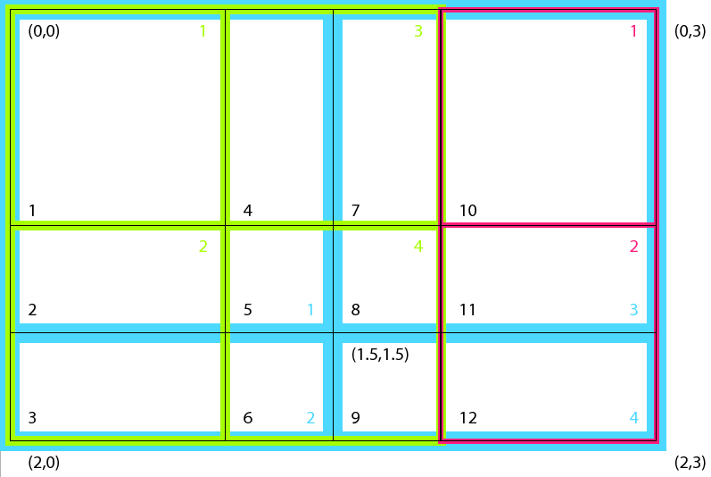 |
We start by creating the Grids on both sides and associate coordinates with the Grids. For details of Grid creation and coordinate use, please refer to Grid class documentation.
sideA(1) = ESMF_GridCreateShapeTile(minIndex=(/1,1/), maxIndex=(/2,2/), &
coordDep1=(/1/), &
coordDep2=(/2/), &
name='source Grid 1 on side A', rc=localrc)
sideA(2) = ESMF_GridCreateShapeTile(minIndex=(/1,1/), maxIndex=(/2,1/), &
coordDep1=(/1/), &
coordDep2=(/2/), &
name='source Grid 2 on side A', rc=localrc)
do i = 1, 2
call ESMF_GridAddCoord(sideA(i), staggerloc=ESMF_STAGGERLOC_CENTER, &
rc=localrc)
if(localrc /= ESMF_SUCCESS) call ESMF_Finalize(rc=localrc, &
terminationflag=ESMF_ABORT)
enddo
Coordinate for the Grids on sideA, refer to the Grid layout diagram for the interpretation of the coordinate values:
! SideA first grid
centroidA1X=(/0.5, 1.5/)
centroidA1Y=(/0.5, 1.5/)
call ESMF_GridGetCoord(sideA(1), localDE=0, &
staggerLoc=ESMF_STAGGERLOC_CENTER, coordDim=1, &
farrayPtr=coordX, rc=localrc)
if(localrc /= ESMF_SUCCESS) call ESMF_Finalize(rc=localrc, &
terminationflag=ESMF_ABORT)
coordX = centroidA1X
call ESMF_GridGetCoord(sideA(1), localDE=0, &
staggerLoc=ESMF_STAGGERLOC_CENTER, coordDim=2, &
farrayPtr=coordY, rc=localrc)
if(localrc /= ESMF_SUCCESS) call ESMF_Finalize(rc=localrc, &
terminationflag=ESMF_ABORT)
coordY = centroidA1Y
! SideA second grid
centroidA2X=(/0.5, 1.5/)
centroidA2Y=(/2.5/)
call ESMF_GridGetCoord(sideA(2), localDE=0, &
staggerLoc=ESMF_STAGGERLOC_CENTER, coordDim=1, &
farrayPtr=coordX, rc=localrc)
if(localrc /= ESMF_SUCCESS) call ESMF_Finalize(rc=localrc, &
terminationflag=ESMF_ABORT)
coordX = centroidA2X
call ESMF_GridGetCoord(sideA(2), localDE=0, &
staggerLoc=ESMF_STAGGERLOC_CENTER, coordDim=2, &
farrayPtr=coordY, rc=localrc)
if(localrc /= ESMF_SUCCESS) call ESMF_Finalize(rc=localrc, &
terminationflag=ESMF_ABORT)
coordY = centroidA2Y
Create the destination grid on side B, only one Grid exists on side B. Also associate coordinate with the Grid:
sideB(1) = ESMF_GridCreateShapeTile(minIndex=(/1,1/), maxIndex=(/2,2/), &
coordDep1=(/1/), coordDep2=(/2/), &
name='destination Grid on side B', rc=localrc)
if(localrc /= ESMF_SUCCESS) call ESMF_Finalize(rc=localrc, &
terminationflag=ESMF_ABORT)
do i = 1, 1
call ESMF_GridAddCoord(sideB(i), staggerloc=ESMF_STAGGERLOC_CENTER, &
rc=localrc)
if(localrc /= ESMF_SUCCESS) call ESMF_Finalize(rc=localrc, &
terminationflag=ESMF_ABORT)
enddo
! SideB grid
centroidBX=(/0.75, 1.75/)
centroidBY=(/0.75, 2.25/)
call ESMF_GridGetCoord(sideB(1), localDE=0, &
staggerLoc=ESMF_STAGGERLOC_CENTER, coordDim=1, farrayPtr=coordX, &
rc=localrc)
if(localrc /= ESMF_SUCCESS) call ESMF_Finalize(rc=localrc, &
terminationflag=ESMF_ABORT)
coordX = centroidBX
call ESMF_GridGetCoord(sideB(1), localDE=0, &
staggerLoc=ESMF_STAGGERLOC_CENTER, coordDim=2, farrayPtr=coordY, &
rc=localrc)
if(localrc /= ESMF_SUCCESS) call ESMF_Finalize(rc=localrc, &
terminationflag=ESMF_ABORT)
coordY = centroidBY
Set up the mapping indices and weights from A side to the XGrid. For details of sequence indices, factorIndexList, and factorList, please see section 22.2.17 in the reference manual. Please refer to the figure above for interpretation of the sequence indices used here.
In order to compute the destination flux on sideB through the XGrid as an mediator, we need to set up the factorList (weights) and factorIndexList (indices) for sparse matrix matmul in this formulation: dst_flux = W'*W*src_flux, where W' is the weight matrix from the XGrid to destination; and W is the weight matrix from source to the XGrid. The weight matrix is generated using destination area weighted algorithm. Please refer to figure 19 for details.
! Set up mapping from A1 -> X
sparseMatA2X(1)%factorIndexList(1,1)=1 ! src seq index (green)
sparseMatA2X(1)%factorIndexList(1,2)=2 ! src seq index (green)
sparseMatA2X(1)%factorIndexList(1,3)=2 ! src seq index (green)
sparseMatA2X(1)%factorIndexList(1,4)=3 ! src seq index (green)
sparseMatA2X(1)%factorIndexList(1,5)=4 ! src seq index (green)
sparseMatA2X(1)%factorIndexList(1,6)=4 ! src seq index (green)
sparseMatA2X(1)%factorIndexList(1,7)=3 ! src seq index (green)
sparseMatA2X(1)%factorIndexList(1,8)=4 ! src seq index (green)
sparseMatA2X(1)%factorIndexList(1,9)=4 ! src seq index (green)
sparseMatA2X(1)%factorIndexList(2,1)=1 ! dst seq index (black)
sparseMatA2X(1)%factorIndexList(2,2)=2 ! dst seq index (black)
sparseMatA2X(1)%factorIndexList(2,3)=3 ! dst seq index (black)
sparseMatA2X(1)%factorIndexList(2,4)=4 ! dst seq index (black)
sparseMatA2X(1)%factorIndexList(2,5)=5 ! dst seq index (black)
sparseMatA2X(1)%factorIndexList(2,6)=6 ! dst seq index (black)
sparseMatA2X(1)%factorIndexList(2,7)=7 ! dst seq index (black)
sparseMatA2X(1)%factorIndexList(2,8)=8 ! dst seq index (black)
sparseMatA2X(1)%factorIndexList(2,9)=9 ! dst seq index (black)
! Set up mapping from A2 -> X
sparseMatA2X(2)%factorIndexList(1,1)=1 ! src seq index (red)
sparseMatA2X(2)%factorIndexList(1,2)=2 ! src seq index (red)
sparseMatA2X(2)%factorIndexList(1,3)=2 ! src seq index (red)
sparseMatA2X(2)%factorIndexList(2,1)=10 ! dst seq index (black)
sparseMatA2X(2)%factorIndexList(2,2)=11 ! dst seq index (black)
sparseMatA2X(2)%factorIndexList(2,3)=12 ! dst seq index (black)
Set up the mapping weights from side A to the XGrid:
! Note that the weights are dest area weighted, they are ratio
! of areas with destination area as the denominator.
! Set up mapping weights from A1 -> X
sparseMatA2X(1)%factorList(:)=1.
! Set up mapping weights from A2 -> X
sparseMatA2X(2)%factorList(:)=1.
Set up the mapping indices and weights from the XGrid to B side:
! Set up mapping from X -> B
sparseMatX2B(1)%factorIndexList(1,1)=1 ! src seq index (black)
sparseMatX2B(1)%factorIndexList(1,2)=2 ! src seq index (black)
sparseMatX2B(1)%factorIndexList(1,3)=3 ! src seq index (black)
sparseMatX2B(1)%factorIndexList(1,4)=4 ! src seq index (black)
sparseMatX2B(1)%factorIndexList(1,5)=5 ! src seq index (black)
sparseMatX2B(1)%factorIndexList(1,6)=6 ! src seq index (black)
sparseMatX2B(1)%factorIndexList(1,7)=7 ! src seq index (black)
sparseMatX2B(1)%factorIndexList(1,8)=8 ! src seq index (black)
sparseMatX2B(1)%factorIndexList(1,9)=9 ! src seq index (black)
sparseMatX2B(1)%factorIndexList(1,10)=10 ! src seq index (black)
sparseMatX2B(1)%factorIndexList(1,11)=11 ! src seq index (black)
sparseMatX2B(1)%factorIndexList(1,12)=12 ! src seq index (black)
sparseMatX2B(1)%factorIndexList(2,1)=1 ! dst seq index (blue)
sparseMatX2B(1)%factorIndexList(2,2)=1 ! dst seq index (blue)
sparseMatX2B(1)%factorIndexList(2,3)=2 ! dst seq index (blue)
sparseMatX2B(1)%factorIndexList(2,4)=1 ! dst seq index (blue)
sparseMatX2B(1)%factorIndexList(2,5)=1 ! dst seq index (blue)
sparseMatX2B(1)%factorIndexList(2,6)=2 ! dst seq index (blue)
sparseMatX2B(1)%factorIndexList(2,7)=3 ! dst seq index (blue)
sparseMatX2B(1)%factorIndexList(2,8)=3 ! dst seq index (blue)
sparseMatX2B(1)%factorIndexList(2,9)=4 ! dst seq index (blue)
sparseMatX2B(1)%factorIndexList(2,10)=3 ! dst seq index (blue)
sparseMatX2B(1)%factorIndexList(2,11)=3 ! dst seq index (blue)
sparseMatX2B(1)%factorIndexList(2,12)=4 ! dst seq index (blue)
! Set up mapping weights from X -> B
sparseMatX2B(1)%factorList(1)=4./9.
sparseMatX2B(1)%factorList(2)=2./9.
sparseMatX2B(1)%factorList(3)=2./3.
sparseMatX2B(1)%factorList(4)=2./9.
sparseMatX2B(1)%factorList(5)=1./9.
sparseMatX2B(1)%factorList(6)=1./3.
sparseMatX2B(1)%factorList(7)=2./9.
sparseMatX2B(1)%factorList(8)=1./9.
sparseMatX2B(1)%factorList(9)=1./3.
sparseMatX2B(1)%factorList(10)=4./9.
sparseMatX2B(1)%factorList(11)=2./9.
sparseMatX2B(1)%factorList(12)=2./3.
Optionally the area can be setup to compute surface area weighted flux integrals:
! Set up destination areas to adjust weighted flux
xgrid_area(1) = 1.
xgrid_area(2) = 0.5
xgrid_area(3) = 0.5
xgrid_area(4) = 0.5
xgrid_area(5) = 0.25
xgrid_area(6) = 0.25
xgrid_area(7) = 0.5
xgrid_area(8) = 0.25
xgrid_area(9) = 0.25
xgrid_area(10) = 1.
xgrid_area(11) = 0.5
xgrid_area(12) = 0.5
Create an XGrid based on the user supplied regridding parameters:
xgrid = ESMF_XGridCreate(sideA, sideB, area=xgrid_area, &
centroid=centroid, sparseMatA2X=sparseMatA2X, &
sparseMatX2B=sparseMatX2B, rc=localrc)
Create an ESMF_Field on the XGrid:
field = ESMF_FieldCreate(xgrid, typekind=ESMF_TYPEKIND_R8, &
rc=localrc)
Query the Field for its Fortran data pointer and its exclusive bounds:
call ESMF_FieldGet(field, farrayPtr=xfarrayPtr, &
exclusiveLBound=xlb, exclusiveUBound=xub, rc=localrc)
Setup and initialize src and dst Fields on side A and side B Grids, source Fields have different source flux:
do i = 1, 2
srcField(i) = ESMF_FieldCreate(sideA(i), &
typekind=ESMF_TYPEKIND_R8, rc=localrc)
if(localrc /= ESMF_SUCCESS) call ESMF_Finalize(rc=localrc, &
terminationflag=ESMF_ABORT)
call ESMF_FieldGet(srcField(i), farrayPtr=farrayPtr, rc=localrc)
if(localrc /= ESMF_SUCCESS) call ESMF_Finalize(rc=localrc, &
terminationflag=ESMF_ABORT)
farrayPtr = i
enddo
do i = 1, 1
dstField(i) = ESMF_FieldCreate(sideB(i), &
typekind=ESMF_TYPEKIND_R8, rc=localrc)
if(localrc /= ESMF_SUCCESS) call ESMF_Finalize(rc=localrc, &
terminationflag=ESMF_ABORT)
call ESMF_FieldGet(dstField(i), farrayPtr=farrayPtr, rc=localrc)
if(localrc /= ESMF_SUCCESS) call ESMF_Finalize(rc=localrc, &
terminationflag=ESMF_ABORT)
farrayPtr = 0.0
enddo
The current implementation requires that Grids used to generate the XGrid must not match, i.e. they are different either topologically or geometrically or both. In this example, the first source Grid is topologically identical to the destination Grid but their geometric coordinates are different. This requirement will be relaxed in a future release.
First we compute the regrid routehandles, these routehandles can be used repeatedly afterwards. Then we initialize the values in the Fields. Finally we execute the Regrid.
! Compute regrid routehandles. The routehandles can be used
! repeatedly afterwards.
! From A -> X
do i = 1, 2
call ESMF_FieldRegridStore(xgrid, srcField(i), field, &
routehandle=rh_src2xgrid(i), rc = localrc)
if(localrc /= ESMF_SUCCESS) call ESMF_Finalize(rc=localrc, &
terminationflag=ESMF_ABORT)
enddo
! from X -> B
do i = 1, 1
call ESMF_FieldRegridStore(xgrid, field, dstField(i), &
routehandle=rh_xgrid2dst(i), rc = localrc)
if(localrc /= ESMF_SUCCESS) call ESMF_Finalize(rc=localrc, &
terminationflag=ESMF_ABORT)
enddo
! Initialize values in the source Fields on side A
do i = 1, 2
call ESMF_FieldGet(srcField(i), farrayPtr=farrayPtr, rc=localrc)
if(localrc /= ESMF_SUCCESS) call ESMF_Finalize(rc=localrc, &
terminationflag=ESMF_ABORT)
farrayPtr = i
enddo
! Initialize values in the destination Field on XGrid
xfarrayPtr = 0.0
! Initialize values in the destination Field on Side B
do i = 1, 1
call ESMF_FieldGet(dstField(i), farrayPtr=farrayPtr, rc=localrc)
if(localrc /= ESMF_SUCCESS) call ESMF_Finalize(rc=localrc, &
terminationflag=ESMF_ABORT)
farrayPtr = 0.0
enddo
First we regrid from the Fields on side A to the Field on the XGrid:
! Execute regrid from A -> X
do i = 1, 2
call ESMF_FieldRegrid(srcField(i), field, &
routehandle=rh_src2xgrid(i), &
zeroflag=ESMF_REGION_SELECT, rc = localrc)
if(localrc /= ESMF_SUCCESS) call ESMF_Finalize(rc=localrc, &
terminationflag=ESMF_ABORT)
enddo
Next we regrid from the Field on XGrid to the destination Field on side B:
! Execute the regrid store
do i = 1, 1
call ESMF_FieldRegrid(field, dstField(i), &
routehandle=rh_xgrid2dst(i), rc = localrc)
if(localrc /= ESMF_SUCCESS) call ESMF_Finalize(rc=localrc, &
terminationflag=ESMF_ABORT)
enddo
In the above example, we first set up all the required paramters to create an XGrid from user supplied input. Then we create Fields on the XGrid and the Grids on either side. Finally we use the ESMF_FieldRegrid() interface to perform a flux exchange from the source side to the destination side.
call ESMF_XGridGet(xgrid, &
ngridA=ngridA, & ! number of Grids on side A
ngridB=ngridB, & ! number of Grids on side B
sideA=l_sideA, & ! list of Grids on side A
sideB=l_sideB, & ! list of Grids on side B
area=l_area, & ! list of area of XGrid
centroid=l_centroid, & ! list of centroid of XGrid
distgridA=l_sideAdg, & ! list of Distgrids on side A
distgridM = distgrid, & ! balanced distgrid
sparseMatA2X=l_sparseMatA2X, & !sparse matrix matmul parameters A to X
sparseMatX2B=l_sparseMatX2B, & !sparse matrix matmul parameters X to B
rc=localrc)
call ESMF_XGridGet(xgrid, localDe=0, &
elementCount=eleCount, & ! elementCount on the localDE
exclusiveCount=ec, & ! exclusive count
exclusiveLBound=elb, & ! exclusive lower bound
exclusiveUBound=eub, & ! exclusive upper bound
rc=localrc)
call ESMF_XGridGet(xgrid, &
xgridSide=ESMF_XGRID_SIDEA, & ! side of the XGrid to query
gridIndex=1, & ! index of the distgrid
distgrid=distgrid, & ! the distgrid returned
rc=localrc)
! After the regridding is successful.
! Clean up all the allocated resources:
call ESMF_FieldDestroy(field, rc=localrc)
if(localrc /= ESMF_SUCCESS) call ESMF_Finalize(rc=localrc, &
terminationflag=ESMF_ABORT)
call ESMF_XGridDestroy(xgrid, rc=localrc)
if(localrc /= ESMF_SUCCESS) call ESMF_Finalize(rc=localrc, &
terminationflag=ESMF_ABORT)
do i = 1, 2
call ESMF_FieldDestroy(srcField(i), rc = localrc)
if(localrc /= ESMF_SUCCESS) call ESMF_Finalize(rc=localrc, &
terminationflag=ESMF_ABORT)
call ESMF_GridDestroy(sideA(i), rc = localrc)
if(localrc /= ESMF_SUCCESS) call ESMF_Finalize(rc=localrc, &
terminationflag=ESMF_ABORT)
enddo
do i = 1, 1
call ESMF_FieldDestroy(dstField(i), rc = localrc)
if(localrc /= ESMF_SUCCESS) call ESMF_Finalize(rc=localrc, &
terminationflag=ESMF_ABORT)
call ESMF_GridDestroy(sideB(i), rc = localrc)
if(localrc /= ESMF_SUCCESS) call ESMF_Finalize(rc=localrc, &
terminationflag=ESMF_ABORT)
enddo
deallocate(sparseMatA2X(1)%factorIndexList, sparseMatA2X(1)%factorList)
deallocate(sparseMatA2X(2)%factorIndexList, sparseMatA2X(2)%factorList)
deallocate(sparseMatX2B(1)%factorIndexList, sparseMatX2B(1)%factorList)
INTERFACE:
interface assignment(=)
xgrid1 = xgrid2
ARGUMENTS:
type(ESMF_XGrid) :: xgrid1
type(ESMF_XGrid) :: xgrid2
DESCRIPTION:
Assign xgrid1 as an alias to the same ESMF XGrid object in memory as xgrid2. If xgrid2 is invalid, then xgrid1 will be equally invalid after the assignment.
The arguments are:
INTERFACE:
interface operator(==)
if (xgrid1 == xgrid2) then ... endif
OR
result = (xgrid1 == xgrid2)
RETURN VALUE:
logical :: resultARGUMENTS:
type(ESMF_XGrid), intent(in) :: xgrid1
type(ESMF_XGrid), intent(in) :: xgrid2
DESCRIPTION:
Test whether xgrid1 and xgrid2 are valid aliases to the same ESMF XGrid object in memory. For a more general comparison of two ESMF XGrids, going beyond the simple alias test, the ESMF_XGridMatch() function (not yet implemented) must be used.
The arguments are:
INTERFACE:
interface operator(/=)
if (xgrid1 == xgrid2) then ... endif
OR
result = (xgrid1 == xgrid2)
RETURN VALUE:
logical :: resultARGUMENTS:
type(ESMF_XGrid), intent(in) :: xgrid1
type(ESMF_XGrid), intent(in) :: xgrid2
DESCRIPTION:
Test whether xgrid1 and xgrid2 are not valid aliases to the same ESMF XGrid object in memory. For a more general comparison of two ESMF XGrids, going beyond the simple alias test, the ESMF_XGridMatch() function (not yet implemented) must be used.
The arguments are:
INTERFACE:
! Private name; call using ESMF_XGridCreate()
function ESMF_XGridCreateRaw(sideA, sideB, area, centroid, &
sparseMatA2X, sparseMatX2A, sparseMatB2X, sparseMatX2B, &
name, &
rc)
ARGUMENTS:
type(ESMF_Grid), intent(in) :: sideA(:), sideB(:) real(ESMF_KIND_R8), intent(in), optional :: area(:) real(ESMF_KIND_R8), intent(in), optional :: centroid(:,:) type(ESMF_XGridSpec), intent(in), optional :: sparseMatA2X(:), sparseMatX2A(:) type(ESMF_XGridSpec), intent(in), optional :: sparseMatB2X(:), sparseMatX2B(:) character (len=*), intent(in), optional :: name integer, intent(out), optional :: rcRETURN VALUE:
type(ESMF_XGrid) :: ESMF_XGridCreateRawDESCRIPTION:
Create an XGrid directly from raw input parameters
The arguments are:
INTERFACE:
subroutine ESMF_XGridDestroy(xgrid, rc)ARGUMENTS:
type(ESMF_XGrid), intent(inout) :: xgrid
integer, intent(out), optional :: rc
DESCRIPTION:
Releases all resources associated with the ESMF_XGrid.
The arguments are:
INTERFACE:
! Private name; call using ESMF_XGridGet()
subroutine ESMF_XGridGetDefault(xgrid, &
sideA, sideB, ngridA, ngridB, area, centroid, &
distgridA, distgridB, distgridM, &
dimCount, localDECount, &
sparseMatA2X, sparseMatX2A, sparseMatB2X, sparseMatX2B, &
name, &
rc)
ARGUMENTS:
type(ESMF_XGrid), intent(in) :: xgrid type(ESMF_Grid), intent(out), optional :: sideA(:), sideB(:) integer, intent(out), optional :: ngridA, ngridB real*8, intent(out), optional :: area(:) real*8, intent(out), optional :: centroid(:,:) type(ESMF_DistGrid), intent(out), optional :: distgridA(:) type(ESMF_DistGrid), intent(out), optional :: distgridB(:) type(ESMF_DistGrid), intent(out), optional :: distgridM integer, intent(out), optional :: dimCount integer, intent(out), optional :: localDECount type(ESMF_XGridSpec), intent(out), optional :: sparseMatA2X(:), sparseMatX2A(:) type(ESMF_XGridSpec), intent(out), optional :: sparseMatB2X(:), sparseMatX2B(:) character (len=*), intent(out), optional :: name integer, intent(out), optional :: rcDESCRIPTION:
Get information about XGrid
The arguments are:
INTERFACE:
! Private name; call using ESMF_XGridGet()
subroutine ESMF_XGridGetDG(xgrid, distgrid, xgridSide, gridIndex, &
rc)
ARGUMENTS:
type(ESMF_XGrid), intent(in) :: xgrid type(ESMF_DistGrid), intent(out) :: distgrid type(ESMF_XGridSide), intent(in), optional :: xgridSide integer, intent(in), optional :: gridIndex integer, intent(out), optional :: rcDESCRIPTION:
Get a distgrid from XGrid from a specific side.
The arguments are:
INTERFACE:
! Private name; call using ESMF_XGridGet()
subroutine ESMF_XGridGetEle(xgrid, &
localDE, elementCount, &
exclusiveCount, exclusiveLBound, exclusiveUBound, &
rc)
ARGUMENTS:
type(ESMF_XGrid), intent(in) :: xgrid integer, intent(in) :: localDE integer, intent(out), optional :: elementCount integer, intent(out), optional :: exclusiveCount integer, intent(out), optional :: exclusiveLBound integer, intent(out), optional :: exclusiveUBound integer, intent(out), optional :: rcDESCRIPTION:
Get localDE specific information about XGrid
The arguments are:
The ESMF DistGrid class sits on top of the DELayout class and holds domain information in index space. A DistGrid object captures the index space topology and describes its decomposition in terms of DEs. Combined with DELayout and VM the DistGrid defines the data distribution of a domain decomposition across the computational resources of an ESMF Component.
The global domain is defined as the union or ``tilework'' of logically rectangular (LR) sub-domains or tiles. The DistGrid create methods allow the specification of such a tilework global domain and its decomposition into exclusive, DE-local LR regions according to various degrees of user specified constraints. Complex index space topologies can be constructed by specifying connection relationships between tiles during creation.
The DistGrid class holds domain information for all DEs. Each DE is associated with a local LR region. No overlap of the regions is allowed. The DistGrid offers query methods that allow DE-local topology information to be extracted, e.g. for the construction of halos by higher classes.
A DistGrid object only contains decomposable dimensions. The minimum rank for a DistGrid object is 1. A maximum rank does not exist for DistGrid objects, however, ranks greater than 7 may lead to difficulties with respect to the Fortran API of higher classes based on DistGrid. The rank of a DELayout object contained within a DistGrid object must be equal to the DistGrid rank. Higher class objects that use the DistGrid, such as an Array object, may be of different rank than the associated DistGrid object. The higher class object will hold the mapping information between its dimensions and the DistGrid dimensions.
The following examples demonstrate how to create, use and destroy DistGrid objects. In order to produce complete and valid DistGrid objects all of the ESMF_DistGridCreate() calls require to be called in unison i.e. on all PETs of a component with a complete set of valid arguments.
The minimum information required to create an ESMF_DistGrid object for a single tile with default decomposition are the corners of the tile in index space. The following call will create a 1D DistGrid for a 1D index space tile with elements from 1 through 1000.
distgrid = ESMF_DistGridCreate(minIndex=(/1/), maxIndex=(/1000/), rc=rc)
A default DELayout with 1 DE per PET will be created during
ESMF_DistGridCreate(). The 1000 elements of the specified 1D tile will
then be block decomposed across the available DEs, i.e. across all PETs.
Hence, for 4 PETs the (min) ![]() (max) corners of the DE-local LR regions
will be:
(max) corners of the DE-local LR regions
will be:
DE 0 - (1) ~ (250)
DE 1 - (251) ~ (500)
DE 2 - (501) ~ (750)
DE 3 - (751) ~ (1000)
DistGrids with rank > 1 can also be created with default decompositions, specifying only the corners of the tile. The following will create a 2D DistGrid for a 5x5 tile with default decomposition.
distgrid = ESMF_DistGridCreate(minIndex=(/1,1/), maxIndex=(/5,5/), rc=rc)
The default decomposition for a DistGrid of rank ![]() will be
will be
![]() , where
, where ![]() is the number of DEs in the DELayout
and there are
is the number of DEs in the DELayout
and there are ![]() factors of
factors of ![]() . For the 2D example above this means
a
. For the 2D example above this means
a ![]() regular decomposition if executed on 4 PETs and will result
in the following DE-local LR regions:
regular decomposition if executed on 4 PETs and will result
in the following DE-local LR regions:
DE 0 - (1,1) ~ (2,5)
DE 1 - (3,1) ~ (3,5)
DE 2 - (4,1) ~ (4,5)
DE 3 - (5,1) ~ (5,5)
In many cases the default decomposition will not suffice for higher rank
DistGrids (rank > 1). For this reason a decomposition descriptor
regDecomp argument is available during ESMF_DistGridCreate(). The
following call creates a DistGrid on the same 2D tile as before, but now with
a user specified regular decomposition of
![]() DEs.
DEs.
distgrid = ESMF_DistGridCreate(minIndex=(/1,1/), maxIndex=(/5,5/), &
regDecomp=(/2,3/), rc=rc)
The default DE labeling sequence follows column major order for the regDecomp argument:
-----------> 2nd dimension
| 0 2 4
| 1 3 5
v
1st dimension
By default grid points along all dimensions are homogeneously divided between
the DEs. The maximum element count difference between DEs along any dimension
is 1. The (min) ![]() (max) corners of the DE-local LR domains of the above
example are as follows:
(max) corners of the DE-local LR domains of the above
example are as follows:
DE 0 - (1,1) ~ (3,2)
DE 1 - (4,1) ~ (5,2)
DE 2 - (1,3) ~ (3,4)
DE 3 - (4,3) ~ (5,4)
DE 4 - (1,5) ~ (3,5)
DE 5 - (4,5) ~ (5,5)
The specifics of the tile decomposition into DE-local LR domains can be modified by the optional decompflag argument. The following line shows how this argument is used to keep ESMF's default decomposition in the first dimension but move extra grid points of the second dimension to the last DEs in that direction. Extra elements occur if the number of DEs for a certain dimension does not evenly divide its extent. In this example there are 2 extra grid points for the second dimension because its extent is 5 but there are 3 DEs along this index space axis.
distgrid = ESMF_DistGridCreate(minIndex=(/1,1/), maxIndex=(/5,5/), &
regDecomp=(/2,3/), decompflag=(/ESMF_DECOMP_DEFAULT, &
ESMF_DECOMP_RESTLAST/), rc=rc)
Now DE 4 and DE 5 will hold the extra elements along the 2nd dimension.
DE 0 - (1,1) ~ (3,1)
DE 1 - (4,1) ~ (5,1)
DE 2 - (1,2) ~ (3,2)
DE 3 - (4,2) ~ (5,2)
DE 4 - (1,3) ~ (3,5)
DE 5 - (4,3) ~ (5,5)
An alternative way of indicating the DE-local LR regions is to list the index space coordinate as given by the associated DistGrid tile for each dimension. For this 2D example there are two lists (dim 1) / (dim 2) for each DE:
DE 0 - (1,2,3) / (1)
DE 1 - (4,5) / (1)
DE 2 - (1,2,3) / (2)
DE 3 - (4,5) / (2)
DE 4 - (1,2,3) / (3,4,5)
DE 5 - (4,5) / (3,4,5)
Information about DE-local LR regions in the latter format can be obtained from the DistGrid object by use of ESMF_DistGridGet() methods:
allocate(dimExtent(2, 0:5)) ! (dimCount, deCount)
call ESMF_DistGridGet(distgrid, delayout=delayout, &
indexCountPDimPDe=dimExtent, rc=rc)
if (rc /= ESMF_SUCCESS) call ESMF_Finalize(terminationflag=ESMF_ABORT)
call ESMF_DELayoutGet(delayout, localDeCount=localDeCount, rc=rc)
if (rc /= ESMF_SUCCESS) call ESMF_Finalize(terminationflag=ESMF_ABORT)
allocate(localDeList(0:localDeCount-1))
call ESMF_DELayoutGet(delayout, localDeList=localDeList, rc=rc)
if (rc /= ESMF_SUCCESS) call ESMF_Finalize(terminationflag=ESMF_ABORT)
do localDe=0, localDeCount-1
de = localDeList(localDe)
do dim=1, 2
allocate(localIndexList(dimExtent(dim, de))) ! allocate list
! to hold indices
call ESMF_DistGridGet(distgrid, localDe=localDe, dim=dim, &
indexList=localIndexList, rc=rc)
if (rc /= ESMF_SUCCESS) call ESMF_Finalize(terminationflag=ESMF_ABORT)
print *, "local DE ", localDe," - DE ",de, &
" localIndexList along dim=", dim," :: ", localIndexList
deallocate(localIndexList)
enddo
enddo
deallocate(localDeList)
deallocate(dimExtent)
The advantage of the localIndexList format over the min-/max-corner format is that it can be used directly for DE-local to tile index dereferencing. Furthermore the localIndexList allows to express very general decompositions such as the cyclic decompositions in the first dimension generated by the following call:
distgrid = ESMF_DistGridCreate(minIndex=(/1,1/), maxIndex=(/5,5/), &
regDecomp=(/2,3/), &
decompflag=(/ESMF_DECOMP_CYCLIC,ESMF_DECOMP_RESTLAST/), rc=rc)
with decomposition:
DE 0 - (1,3,5) / (1)
DE 1 - (2,4) / (1)
DE 2 - (1,3,5) / (2)
DE 3 - (2,4) / (2)
DE 4 - (1,3,5) / (3,4,5)
DE 5 - (2,4) / (3,4,5)
Finally, a DistGrid object is destroyed by calling
call ESMF_DistGridDestroy(distgrid, rc=rc)
The examples of this section use the 2D DistGrid of the previous section to show the interplay between DistGrid and DELayout. By default, i.e. without specifying the delayout argument, a DELayout will be created during DistGrid creation that provides as many DEs as the DistGrid object requires. The implicit call to ESMF_DELayoutCreate() is issued with a fixed number of DEs and default settings in all other aspects. The resulting DE to PET mapping depends on the number of PETs of the current VM context. Assuming 6 PETs in the VM
distgrid = ESMF_DistGridCreate(minIndex=(/1,1/), maxIndex=(/5,5/), &
regDecomp=(/2,3/), rc=rc)
will result in the following domain decomposition in terms of DEs
0 2 4
1 3 5
and their layout or distribution over the available PETs:
DE 0 -> PET 0
DE 1 -> PET 1
DE 2 -> PET 2
DE 3 -> PET 3
DE 4 -> PET 4
DE 5 -> PET 5
Running the same example on a 4 PET VM will not change the domain decomposition into 6 DEs as specified by
0 2 4
1 3 5
but the layout across PETs will now contain multiple DE-to-PET mapping with
default cyclic distribution:
DE 0 -> PET 0
DE 1 -> PET 1
DE 2 -> PET 2
DE 3 -> PET 3
DE 4 -> PET 0
DE 5 -> PET 1
Sometimes it may be desirable for performance tuning to construct a DELayout with specific characteristics. For instance, if the 6 PETs of the above example are running on 3 nodes of a dual-SMP node cluster and there is a higher communication load along the first dimension of the model than along the second dimension it would be sensible to place DEs according to this knowledge.
The following example first creates a DELayout with 6 DEs where groups of 2 DEs are to be in fast connection. This DELayout is then used to create a DistGrid.
delayout = ESMF_DELayoutCreate(deCount=6, deGrouping=(/(i/2,i=0,5)/), rc=rc)
distgrid = ESMF_DistGridCreate(minIndex=(/1,1/), maxIndex=(/5,5/), &
regDecomp=(/2,3/), delayout=delayout, rc=rc)
This will ensure a distribution of DEs across the cluster resource in the following way:
0 2 4
1 3 5
SMP SMP SMP
The interplay between DistGrid and DELayout may at first seem complicated. The simple but important rule to understand is that DistGrid describes a domain decomposition and each domain is labeled with a DE number. The DELayout describes how these DEs are laid out over the compute resources of the VM, i.e. PETs. The DEs are purely logical elements of decomposition and may be relabeled to fit the algorithm or legacy code better. The following example demonstrates this by describing the exact same distribution of the domain data across the fictitious cluster of SMP-nodes with a different choice of DE labeling:
delayout = ESMF_DELayoutCreate(deCount=6, deGrouping=(/(mod(i,3),i=0,5)/), &
rc=rc)
distgrid = ESMF_DistGridCreate(minIndex=(/1,1/), maxIndex=(/5,5/), &
regDecomp=(/2,3/), deLabelList=(/0,3,1,4,2,5/), delayout=delayout, rc=rc)
Here the deLabelList argument changes the default DE label sequence from column major to row major. The DELayout compensates for this change in DE labeling by changing the deGrouping argument to map the first dimension to SMP nodes as before. The decomposition and layout now looks as follows:
0 1 2
3 4 5
SMP SMP SMP
Finally, in order to achieve a completely user-defined distribution of the domain data across the PETs of the VM a DELayout may be created from a petMap before using it in the creation of a DistGrid. If for instance the desired distribution of a 2 x 3 decomposition puts the DEs of the first row onto 3 separate PETs (PET 0, 1, 2) and groups the DEs of the second row onto PET 3 a petMap must first be setup that takes the DE labeling of the DistGrid into account.The following lines of code result in the desired distribution using column major DE labeling by first create a DELayout and then using it in the DistGrid creation.
delayout = ESMF_DELayoutCreate(petMap=(/0,3,1,3,2,3/), rc=rc)
distgrid = ESMF_DistGridCreate(minIndex=(/1,1/), maxIndex=(/5,5/), &
regDecomp=(/2,3/), delayout=delayout, rc=rc)
This decomposes the global domain into
0 2 4
1 3 5
and associates the DEs to the following PETs:
DE 0 -> PET 0
DE 1 -> PET 3
DE 2 -> PET 1
DE 3 -> PET 3
DE 4 -> PET 2
DE 5 -> PET 3
The examples of the previous sections showed how DistGrid objects with regular decompositions are created. However, in some cases a regular decomposition may not be specific enough. The following example shows how the deBlockList argument is used to create a DistGrid object with completely user-defined decomposition.
A single 5x5 LR domain is to be decomposed into 6 DEs. To this end a list is constructed that holds the min and max corners of all six DE LR blocks. The DE-local LR blocks are arranged as to cover the whole tile domain without overlap.
allocate(deBlockList(2, 2, 6)) ! (dimCount, 2, deCount) deBlockList(:,1,1) = (/1,1/) ! minIndex 1st deBlock deBlockList(:,2,1) = (/3,2/) ! maxIndex 1st deBlock deBlockList(:,1,2) = (/4,1/) ! minIndex 2nd deBlock deBlockList(:,2,2) = (/5,2/) ! maxIndex 2nd deBlock deBlockList(:,1,3) = (/1,3/) deBlockList(:,2,3) = (/2,4/) deBlockList(:,1,4) = (/3,3/) deBlockList(:,2,4) = (/5,4/) deBlockList(:,1,5) = (/1,5/) deBlockList(:,2,5) = (/3,5/) deBlockList(:,1,6) = (/4,5/) ! minIndex 6th deBlock deBlockList(:,2,6) = (/5,5/) ! maxInbex 6th deBlock
distgrid = ESMF_DistGridCreate(minIndex=(/1,1/), maxIndex=(/5,5/), &
deBlockList=deBlockList, rc=rc)
By default the edges of all tiles have solid wall boundary conditions. Periodic boundary conditions can be imposed by specifying connections between tiles. For the single LR domain of the last section periodic boundaries along the first dimension are imposed by adding a connectionList argument with only one element to the create call.
Each connectionList element is a vector of (2 * dimCount + 2) integer numbers:
allocate(connectionList(2*2+2, 1)) ! (2*dimCount+2, number of connections)
and has the following format:
(/tileIndex_A, tileIndex_B, positionVector, orientationVector/).
The following constructor call can be used to construct a suitable connectionList element.
call ESMF_DistGridConnection(connection=connectionList(:,1), &
tileIndexA=1, tileIndexB=1, &
positionVector=(/5, 0/), &
orientationVector=(/1, 2/), &
rc=rc)
The tileIndexA and tileIndexB arguments specify that this is a connection within tile 1. The positionVector indicates that there is no offset between tileB and tileA along the second dimension, but there is an offset of 5 along the first dimension (which in this case is the length of dimension 1). This aligns tileB (which is tile 1) right next to tileA (which is also tile 1).
The orientationVector fixes the orientation of the tileB index space to be the same as the orientation of tileA (it maps index 1 of tileA to index 1 of tileB and the same for index 2). The orientationVector could have been omitted in this case which corresponds to the default orientation.
The connectionList can now be used to create a DistGrid object with the desired boundary conditions.
distgrid = ESMF_DistGridCreate(minIndex=(/1,1/), maxIndex=(/5,5/), &
deBlockList=deBlockList, connectionList=connectionList, rc=rc)
deallocate(connectionList)
This closes the tile along the first dimension on itself, thus imposing periodic boundaries along this direction.
Creating a DistGrid from a list of LR domains is a straight forward extension of the case with a single LR domain. The first four arguments of ESMF_DistGridCreate() are promoted to rank 2, the second dimension being the tile count index.
The following 2D tilework domain consisting of 3 LR tiles will be used in the examples of this section:
----------------------------------------> 2nd dim
|
| (1,11)-----(1,20)
| | |
| | |
| | |
| | |
| | |
| (10,11)---(10,20)
| (11,1)----(11,10)(11,11)---(11,20)
| | || |
| | || |
| | || |
| | || |
| | || |
| (20,1)----(20,10)(20,11)---(20,20)
|
|
v
1st dim
The first step in creating a tilework global domain is to construct the minIndex and maxIndex arrays.
allocate(minIndex(2,3)) ! (dimCount, number of tiles) allocate(maxIndex(2,3)) ! (dimCount, number of tiles) minIndex(:,1) = (/11,1/) maxIndex(:,1) = (/20,10/) minIndex(:,2) = (/11,11/) maxIndex(:,2) = (/20,20/) minIndex(:,3) = (/1,11/) maxIndex(:,3) = (/10,20/)
Next the regular decomposition for each tile is set up in the regDecomp array. In this example each tile is associated with a single DE.
allocate(regDecomp(2,3)) ! (dimCount, number of tiles) regDecomp(:,1) = (/1,1/) ! one DE regDecomp(:,2) = (/1,1/) ! one DE regDecomp(:,3) = (/1,1/) ! one DE
Finally the DistGrid can be created by calling
distgrid = ESMF_DistGridCreate(minIndex=minIndex, maxIndex=maxIndex, &
regDecomp=regDecomp, rc=rc)
The default DE labeling sequence is identical to the tile labeling sequence and follows the sequence in which the tiles are defined during the create call. However, DE labels start at 0 whereas tile labels start at 1. In this case the DE labels look as:
2
0 1
Each tile can be decomposed differently into DEs. The default DE labeling follows the column major order for each tile. This is demonstrated in the following case where the tilework global domain is decomposed into 9 DEs,
regDecomp(:,1) = (/2,2/) ! 4 DEs
regDecomp(:,2) = (/1,3/) ! 3 DEs
regDecomp(:,3) = (/2,1/) ! 2 DEs
distgrid = ESMF_DistGridCreate(minIndex=minIndex, maxIndex=maxIndex, &
regDecomp=regDecomp, rc=rc)
resulting in the following decomposition:
+-------+
| 7 |
| |
| 8 |
+-------+-------+
| 0 2 | |
| | 4 5 6 |
| 1 3 | |
+-------+-------+
DE 0 - (11,1) ~ (15,5)
DE 1 - (16,1) ~ (20,5)
DE 2 - (11,6) ~ (15,10)
DE 3 - (16,6) ~ (20,10)
DE 4 - (11,11) ~ (20,14)
DE 5 - (11,15) ~ (20,17)
DE 6 - (11,18) ~ (20,20)
DE 7 - (1,11) ~ (5,20)
DE 8 - (6,11) ~ (10,20)
The decompflag and deLabelList arguments can be used much like in the single LR domain case to overwrite the default grid decomposition (per tile) and to change the overall DE labeling sequence, respectively.
The DistGrid class supports the communication methods of higher classes, like Array and Field, by associating a unique sequence index with each DistGrid index tuple. This sequence index can be used to address every Array or Field element. By default, the DistGrid does not actually generate and store the sequence index of each element. Instead a default sequence through the elements is implemented in the DistGrid code. This default sequence is used internally when needed.
The DistGrid class provides two ESMF_DistGridCreate() calls that allow the user to specify arbitrary sequence indices, overriding the use of the default sequence index scheme. The user sequence indices are passed to the DistGrid in form of 1d Fortran arrays, one array on each PET. The local size of this array on each PET determines the number of DistGrid elements on the PET. The supplied sequence indices must be unique across all PETs.
allocate(arbSeqIndexList(10)) ! each PET will have 10 elements
do i=1, 10
arbSeqIndexList(i) = (i-1)*petCount + localPet ! initialize unique
! seq. indices
enddo
A default DELayout will be created automatically during ESMF_DistGridCreate(), associating 1 DE per PET.
distgrid = ESMF_DistGridCreate(arbSeqIndexList=arbSeqIndexList, rc=rc)
The user provided sequence index array can be deallocated once it has been used.
deallocate(arbSeqIndexList)
The distgrid object can be used just like any other DistGrid object. The "arbitrary" nature of distgrid will only become visible during Array or Field communication methods, where source and destination objects map elements according to the sequence indices provided by the associated DistGrid objects.
call ESMF_DistGridDestroy(distgrid, rc=rc)
The second ESMF_DistGridCreate() call, that accepts the arbSeqIndexList argument, allows the user to specify additional, regular DistGrid dimensions. These additional DistGrid dimensions are not decomposed across DEs, but instead are simply "added" or "multiplied" to the 1D arbitrary dimension.
The same arbSeqIndexList array as before is used to define the user supplied sequence indices.
allocate(arbSeqIndexList(10)) ! each PET will have 10 elements
do i=1, 10
arbSeqIndexList(i) = (i-1)*petCount + localPet ! initialize unique
! seq. indices
enddo
The additional DistGrid dimensions are specified in the usual manner using minIndex and maxIndex arguments. The dimCount of the resulting DistGrid is the size of the minIndex and maxIndex arguments plus 1 for the arbitrary dimension. The arbDim argument is used to indicate which or the resulting DistGrid dimensions is associated with the arbitrary sequence indices provided by the user.
distgrid = ESMF_DistGridCreate(arbSeqIndexList=arbSeqIndexList, &
arbDim=1, minIndex=(/1,1/), maxIndex=(/5,7/), rc=rc)
deallocate(arbSeqIndexList)
call ESMF_DistGridDestroy(distgrid, rc=rc)
This section will be updated as the implementation of the DistGrid class nears completion.
INTERFACE:
interface assignment(=)
distgrid1 = distgrid2
ARGUMENTS:
type(ESMF_DistGrid) :: distgrid1
type(ESMF_DistGrid) :: distgrid2
STATUS:
Backward compatible starting with ESMF 5.2r.
DESCRIPTION:
Assign distgrid1 as an alias to the same ESMF DistGrid object in memory as distgrid2. If distgrid2 is invalid, then distgrid1 will be equally invalid after the assignment.
The arguments are:
INTERFACE:
interface operator(==)
if (distgrid1 == distgrid2) then ... endif
OR
result = (distgrid1 == distgrid2)
RETURN VALUE:
logical :: resultARGUMENTS:
type(ESMF_DistGrid), intent(in) :: distgrid1
type(ESMF_DistGrid), intent(in) :: distgrid2
STATUS:
Backward compatible starting with ESMF 5.2r.
DESCRIPTION:
Test whether distgrid1 and distgrid2 are valid aliases to the same ESMF DistGrid object in memory. For a more general comparison of two ESMF DistGrids, going beyond the simple alias test, the ESMF_DistGridMatch() function (not yet fully implemented) must be used.
The arguments are:
INTERFACE:
interface operator(/=)
if (distgrid1 == distgrid2) then ... endif
OR
result = (distgrid1 == distgrid2)
RETURN VALUE:
logical :: resultARGUMENTS:
type(ESMF_DistGrid), intent(in) :: distgrid1
type(ESMF_DistGrid), intent(in) :: distgrid2
STATUS:
Backward compatible starting with ESMF 5.2r.
DESCRIPTION:
Test whether distgrid1 and distgrid2 are not valid aliases to the same ESMF DistGrid object in memory. For a more general comparison of two ESMF DistGrids, going beyond the simple alias test, the ESMF_DistGridMatch() function (not yet fully implemented) must be used.
The arguments are:
INTERFACE:
! Private name; call using ESMF_DistGridCreate()
function ESMF_DistGridCreateDG(distgrid, &
firstExtra, lastExtra, indexflag, connectionList, rc)
ARGUMENTS:
type(ESMF_DistGrid), intent(in) :: distgrid
-- The following arguments require argument keyword syntax (e.g. rc=rc). --
integer, target, intent(in), optional :: firstExtra(:)
integer, target, intent(in), optional :: lastExtra(:)
type(ESMF_IndexFlag), intent(in), optional :: indexflag
integer, target, intent(in), optional :: connectionList(:,:)
integer, intent(out),optional :: rc
RETURN VALUE:
type(ESMF_DistGrid) :: ESMF_DistGridCreateDGSTATUS: Backward compatible starting with ESMF 5.2r.
DESCRIPTION:
Create a new DistGrid from an existing DistGrid, keeping the decomposition unchanged. The firstExtra and lastExtra arguments allow extra elements to be added at the first/last edge DE in each dimension. The method also allows the indexflag to be set. Further, if the connectionList argument is passed in it will be used to set connections in the newly created DistGrid, otherwise the connections of the incoming DistGrid will be used. If neither firstExtra, lastExtra, indexflag, nor connectionList arguments are specified, the method reduces to a deep copy of the incoming DistGrid object.
The arguments are:
(/tileIndex_A, tileIndex_B, positionVector, orientationVector/) where:
INTERFACE:
! Private name; call using ESMF_DistGridCreate()
function ESMF_DistGridCreateDGP(distgrid, firstExtra, lastExtra, &
indexflag, connectionList, rc)
ARGUMENTS:
type(ESMF_DistGrid), intent(in) :: distgrid
integer, target, intent(in) :: firstExtra(:,:)
integer, target, intent(in) :: lastExtra(:,:)
-- The following arguments require argument keyword syntax (e.g. rc=rc). --
type(ESMF_IndexFlag), intent(in), optional :: indexflag
integer, target, intent(in), optional :: connectionList(:,:)
integer, intent(out),optional :: rc
RETURN VALUE:
type(ESMF_DistGrid) :: ESMF_DistGridCreateDGPSTATUS: Backward compatible starting with ESMF 5.2r.
DESCRIPTION:
Create a new DistGrid from an existing DistGrid, keeping the decomposition unchanged. The firstExtra and lastExtra arguments allow extra elements to be added at the first/last edge DE in each dimension. The method also allows the indexflag to be set. Further, if the connectionList argument is passed in it will be used to set connections in the newly created DistGrid, otherwise the connections of the incoming DistGrid will be used. If neither firstExtra, lastExtra, indexflag, nor connectionList arguments are specified, the method reduces to a deep copy of the incoming DistGrid object.
The arguments are:
INTERFACE:
! Private name; call using ESMF_DistGridCreate()
function ESMF_DistGridCreateRD(minIndex, maxIndex, regDecomp, &
decompflag, regDecompFirstExtra, regDecompLastExtra, deLabelList, &
indexflag, connectionList, delayout, vm, rc)
ARGUMENTS:
integer, intent(in) :: minIndex(:)
integer, intent(in) :: maxIndex(:)
-- The following arguments require argument keyword syntax (e.g. rc=rc). --
integer, target,intent(in), optional :: regDecomp(:)
type(ESMF_DecompFlag), target,intent(in), optional :: decompflag(:)
integer, target,intent(in), optional :: regDecompFirstExtra(:)
integer, target,intent(in), optional :: regDecompLastExtra(:)
integer, target,intent(in), optional :: deLabelList(:)
type(ESMF_IndexFlag), intent(in), optional :: indexflag
integer, target,intent(in), optional :: connectionList(:,:)
type(ESMF_DELayout), intent(in), optional :: delayout
type(ESMF_VM), intent(in), optional :: vm
integer, intent(out),optional :: rc
RETURN VALUE:
type(ESMF_DistGrid) :: ESMF_DistGridCreateRDSTATUS: Backward compatible starting with ESMF 5.2r.
DESCRIPTION:
Create an ESMF_DistGrid from a single logically rectangular (LR) tile with regular decomposition. A regular decomposition is of the same rank as the tile and decomposes each dimension into a fixed number of DEs. A regular decomposition of a single tile is expressed by a single regDecomp list of DE counts in each dimension.
The arguments are:
(/tileIndex_A, tileIndex_B, positionVector, orientationVector/) where:
INTERFACE:
! Private name; call using ESMF_DistGridCreate()
function ESMF_DistGridCreateDB(minIndex, maxIndex, deBlockList, &
deLabelList, indexflag, connectionList, delayout, vm, rc)
ARGUMENTS:
integer, intent(in) :: minIndex(:)
integer, intent(in) :: maxIndex(:)
integer, intent(in) :: deBlockList(:,:,:)
-- The following arguments require argument keyword syntax (e.g. rc=rc). --
integer, intent(in), optional :: deLabelList(:)
type(ESMF_IndexFlag), intent(in), optional :: indexflag
integer, intent(in), optional :: connectionList(:,:)
type(ESMF_DELayout), intent(in), optional :: delayout
type(ESMF_VM), intent(in), optional :: vm
integer, intent(out),optional :: rc
RETURN VALUE:
type(ESMF_DistGrid) :: ESMF_DistGridCreateDBSTATUS: Backward compatible starting with ESMF 5.2r.
DESCRIPTION:
Create an ESMF_DistGrid from a single logically rectangular (LR) tile with decomposition specified by deBlockList.
The arguments are:
+---------------------------------------> 2nd index
| 1 2
| 1 minIndex(1) maxIndex(1)
| 2 minIndex(2) maxIndex(2)
| . minIndex(.) maxIndex(.)
| .
v
1st index
It is required that there be no overlap between the LR segments
defined by deBlockList.
(/tileIndex_A, tileIndex_B, positionVector, orientationVector/) where:
INTERFACE:
! Private name; call using ESMF_DistGridCreate()
function ESMF_DistGridCreateRDP(minIndex, maxIndex, regDecomp,&
decompflag, regDecompFirstExtra, regDecompLastExtra, deLabelList, &
indexflag, connectionList, delayout, vm, rc)
ARGUMENTS:
integer, intent(in) :: minIndex(:,:)
integer, intent(in) :: maxIndex(:,:)
-- The following arguments require argument keyword syntax (e.g. rc=rc). --
integer, intent(in), optional :: regDecomp(:,:)
type(ESMF_DecompFlag),target, intent(in), optional :: decompflag(:,:)
integer, target, intent(in), optional :: regDecompFirstExtra(:,:)
integer, target, intent(in), optional :: regDecompLastExtra(:,:)
integer, intent(in), optional :: deLabelList(:)
type(ESMF_IndexFlag), intent(in), optional :: indexflag
integer, intent(in), optional :: connectionList(:,:)
type(ESMF_DELayout), intent(in), optional :: delayout
type(ESMF_VM), intent(in), optional :: vm
integer, intent(out),optional :: rc
RETURN VALUE:
type(ESMF_DistGrid) :: ESMF_DistGridCreateRDPSTATUS: Backward compatible starting with ESMF 5.2r.
DESCRIPTION:
Create an ESMF_DistGrid from a tilework of logically rectangular (LR) tiles with regular decomposition. A regular decomposition is of the same rank as the tile and decomposes each dimension into a fixed number of DEs. A regular decomposition of a tilework of tiles is expressed by a list of DE count vectors, one vector for each tile. Each vector contained in the regDecomp argument ascribes DE counts for each dimension. It is erroneous to provide more tiles than there are DEs.
The arguments are:
(/tileIndex_A, tileIndex_B, positionVector, orientationVector/) where:
INTERFACE:
! Private name; call using ESMF_DistGridCreate() function ESMF_DistGridCreateDBAI1D(arbSeqIndexList, rc)ARGUMENTS:
integer, intent(in) :: arbSeqIndexList(:)
-- The following arguments require argument keyword syntax (e.g. rc=rc). --
integer, intent(out),optional :: rc
RETURN VALUE:
type(ESMF_DistGrid) :: ESMF_DistGridCreateDBAI1DSTATUS: Backward compatible starting with ESMF 5.2r.
DESCRIPTION:
Create an ESMF_DistGrid of dimCount 1 from a PET-local list of sequence indices. The PET-local size of the arbSeqIndexList argument determines the number of local elements in the created DistGrid. The sequence indices must be unique across all PETs. A default DELayout with 1 DE per PET across all PETs of the current VM is automatically created.
The arguments are:
INTERFACE:
! Private name; call using ESMF_DistGridCreate()
function ESMF_DistGridCreateDBAI(arbSeqIndexList, arbDim, &
minIndex, maxIndex, rc)
ARGUMENTS:
integer, intent(in) :: arbSeqIndexList(:)
integer, intent(in) :: arbDim
integer, intent(in) :: minIndex(:)
integer, intent(in) :: maxIndex(:)
-- The following arguments require argument keyword syntax (e.g. rc=rc). --
integer, intent(out),optional :: rc
RETURN VALUE:
type(ESMF_DistGrid) :: ESMF_DistGridCreateDBAISTATUS: Backward compatible starting with ESMF 5.2r.
DESCRIPTION:
Create an ESMF_DistGrid of dimCount ![]() , where
, where
![]() size(minIndex) = size(maxIndex).
size(minIndex) = size(maxIndex).
The resulting DistGrid will have a 1D distribution determined by the PET-local arbSeqIndexList. The PET-local size of the arbSeqIndexList argument determines the number of local elements along the arbitrarily distributed dimension in the created DistGrid. The sequence indices must be unique across all PETs. The associated, automatically created DELayout will have 1 DE per PET across all PETs of the current VM.
In addition to the arbitrarily distributed dimension, regular DistGrid
dimensions can be specified in minIndex and maxIndex. The
![]() dimensional subspace spanned by the regular dimensions is "multiplied"
with the arbitrary dimension on each DE, to form a
dimensional subspace spanned by the regular dimensions is "multiplied"
with the arbitrary dimension on each DE, to form a ![]() dimensional
total index space described by the DistGrid object. The arbDim
argument allows to specify which dimension in the resulting DistGrid
corresponds to the arbitrarily distributed one.
dimensional
total index space described by the DistGrid object. The arbDim
argument allows to specify which dimension in the resulting DistGrid
corresponds to the arbitrarily distributed one.
The arguments are:
INTERFACE:
subroutine ESMF_DistGridDestroy(distgrid, rc)ARGUMENTS:
type(ESMF_DistGrid), intent(inout) :: distgrid
-- The following arguments require argument keyword syntax (e.g. rc=rc). --
integer, intent(out), optional :: rc
STATUS:
Backward compatible starting with ESMF 5.2r.
DESCRIPTION:
Destroy an ESMF_DistGrid object.
The arguments are:
INTERFACE:
! Private name; call using ESMF_DistGridGet()
subroutine ESMF_DistGridGetDefault(distgrid, delayout, dimCount, &
tileCount, minIndexPDimPTile, maxIndexPDimPTile, elementCountPTile, &
minIndexPDimPDe, maxIndexPDimPDe, elementCountPDe, tileListPDe, &
indexCountPDimPDe, collocationPDim, regDecompFlag, rc)
ARGUMENTS:
type(ESMF_DistGrid), intent(in) :: distgrid
-- The following arguments require argument keyword syntax (e.g. rc=rc). --
type(ESMF_DELayout), intent(out), optional :: delayout
integer, intent(out), optional :: dimCount
integer, intent(out), optional :: tileCount
integer, target, intent(out), optional :: minIndexPDimPTile(:,:)
integer, target, intent(out), optional :: maxIndexPDimPTile(:,:)
integer, target, intent(out), optional :: elementCountPTile(:)
integer, target, intent(out), optional :: minIndexPDimPDe(:,:)
integer, target, intent(out), optional :: maxIndexPDimPDe(:,:)
integer, target, intent(out), optional :: elementCountPDe(:)
integer, target, intent(out), optional :: tileListPDe(:)
integer, target, intent(out), optional :: indexCountPDimPDe(:,:)
integer, target, intent(out), optional :: collocationPDim(:)
logical, intent(out), optional :: regDecompFlag
integer, intent(out), optional :: rc
DESCRIPTION:
Get internal DistGrid information.
The arguments are:
INTERFACE:
! Private name; call using ESMF_DistGridGet()
subroutine ESMF_DistGridGetPLocalDe(distgrid, localDe, &
collocation, arbSeqIndexFlag, seqIndexList, elementCount, rc)
ARGUMENTS:
type(ESMF_DistGrid), intent(in) :: distgrid
integer, intent(in) :: localDe
-- The following arguments require argument keyword syntax (e.g. rc=rc). --
integer, intent(in), optional :: collocation
logical, intent(out), optional :: arbSeqIndexFlag
integer, target, intent(out), optional :: seqIndexList(:)
integer, intent(out), optional :: elementCount
integer, intent(out), optional :: rc
STATUS:
Backward compatible starting with ESMF 5.2r.
DESCRIPTION:
Get internal DistGrid information.
The arguments are:
INTERFACE:
! Private name; call using ESMF_DistGridGet()
subroutine ESMF_DistGridGetPLocalDePDim(distgrid, localDe, dim, &
indexList, rc)
ARGUMENTS:
type(ESMF_DistGrid), intent(in) :: distgrid
integer, intent(in) :: localDe
integer, intent(in) :: dim
integer, target, intent(out) :: indexList(:)
-- The following arguments require argument keyword syntax (e.g. rc=rc). --
integer, intent(out), optional :: rc
STATUS:
Backward compatible starting with ESMF 5.2r.
DESCRIPTION:
Get internal DistGrid information.
The arguments are:
INTERFACE:
subroutine ESMF_DistGridPrint(distgrid, rc)ARGUMENTS:
type(ESMF_DistGrid), intent(in) :: distgrid
-- The following arguments require argument keyword syntax (e.g. rc=rc). --
integer, intent(out), optional :: rc
STATUS:
Backward compatible starting with ESMF 5.2r.
DESCRIPTION:
Prints internal information about the specified ESMF_DistGrid
object to stdout.
Note: Many ESMF_<class>Print methods are implemented in C++.
On some platforms/compilers there is a potential issue with interleaving
Fortran and C++ output to stdout such that it doesn't appear in
the expected order. If this occurs, the ESMF_IOUnitFlush() method
may be used on unit 6 to get coherent output.
The arguments are:
INTERFACE:
function ESMF_DistGridMatch(distgrid1, distgrid2, rc)RETURN VALUE:
logical :: ESMF_DistGridMatchARGUMENTS:
type(ESMF_DistGrid), intent(in) :: distgrid1
type(ESMF_DistGrid), intent(in) :: distgrid2
-- The following arguments require argument keyword syntax (e.g. rc=rc). --
integer, intent(out), optional :: rc
DESCRIPTION:
Check if distgrid1 and distgrid2 match. Returns .TRUE. if DistGrid objects match, .FALSE. otherwise.
The arguments are:
INTERFACE:
subroutine ESMF_DistGridValidate(distgrid, rc)ARGUMENTS:
type(ESMF_DistGrid), intent(in) :: distgrid
-- The following arguments require argument keyword syntax (e.g. rc=rc). --
integer, intent(out), optional :: rc
STATUS:
Backward compatible starting with ESMF 5.2r.
DESCRIPTION:
Validates that the distgrid is internally consistent. The method returns an error code if problems are found.
The arguments are:
INTERFACE:
subroutine ESMF_DistGridConnection(connection, tileIndexA, tileIndexB, &
positionVector, orientationVector, rc)
ARGUMENTS:
integer, target, intent(out) :: connection(:)
integer, intent(in) :: tileIndexA
integer, intent(in) :: tileIndexB
integer, intent(in) :: positionVector(:)
-- The following arguments require argument keyword syntax (e.g. rc=rc). --
integer, intent(in), optional :: orientationVector(:)
integer, intent(out), optional :: rc
STATUS:
Backward compatible starting with ESMF 5.2r.
DESCRIPTION:
This call helps to construct a DistGrid connection, which is a simple vector of integers, out of its components.
The arguments are:
The ESMF IO provides an unified interface for input and output of high level ESMF objects such as Fields. In the current release, the ESMF IO capability is integrated with third-party software such as Parallel IO (PIO) to read and write Fortran array data in MPI_IO binary or NetCDF format, and Xerces Library to read and write Attribute data in XML format. Other file IO functionalities, such as writing of error and log messages, input of configuration parameters from an ASCII file, and lower-level IO utilites are covered in different sections of this document. See the Log Class 42.1, the Config Class 41.1, and the Fortran I/O Utilities, 45.1 respectively.
Metadata IO is handled via the ESMF Attribute class. The third party software Xerces C++ Library is used by ESMF to provide the ability to read and write Attribute data in XML file format. To enable this capability, the environment variable ESMF_XERCES must be set. Details can be found in the ESMF User Guide, "Building and Installing the ESMF", "Third Party Libraries".
In the current release, the following methods support Attribute XML I/O using Xerces:
ESMF provides interfaces for high performance, parallel I/O using ESMF data objects such as Arrays and Fields. Currently ESMF supports I/O of binary and NetCDF files. The current ESMF implementation relies on the Parallel I/O (PIO) library developed as a collaboration between NCAR and DOE laboratories. PIO is built as part of the ESMF build when the environment variable ESMF_PIO is set to "internal"; by default it is not set. When PIO is built with ESMF, the ESMF methods internally call the PIO interfaces. When PIO is not built with ESMF, the ESMF methods are non-operable (no-op) stubs that simply return with a return code of ESMF_RC_LIB_NOT_PRESENT. Details about the environment variables can be found in ESMF User Guide, "Building and Installing the ESMF", "Third Party Libraries".
In the current release, the following methods support parallel data I/O using PIO:
Two formats are supported, namely, NetCDF and binary (through MPI_IO). The environment variables that are enabled when ESMF is built determine the format. The environment variables ESMF_NETCDF or/and ESMF_PNETCDF should be set to "standard" to enable NetCDF IO format. If neither ESMF_NETCDF nor ESMF_PNETCDF are set, and MPI_IO is enabled in MPI, the format will be binary. Details about the environment variables can be found in ESMF User Guide, "Building and Installing the ESMF", "Third Party Libraries".
To the extent that data on unstructured grids (or even observations) can be represented as one-dimensional arrays, NetCDF can also be used to store these data. However, it does not provide a high-level abstraction for this type of data.
Currently a small fraction of the anticipated data formats is implemented by ESMF. The data IO uses NetCDF and MPI_IO binary formats, and ESMF Attribute IO uses XML format. Different libraries are employed for these different formats. In future development, a more centralized IO technique will likely be defined to provide efficient utilities with a set of standard APIs that will allow manipulation of multiple standard formats. Also, the ability to automatically detect file formats at runtime will be developed.
For data IO, the ESMF IO capability relies on the PIO, NetCDF, PNetCDF and MPI_IO libraries. For Attribute IO, the ESMF IO capability uses the Xerces library to perform reading and writing of XML files. PIO is included with the ESMF distribution; the other libraries must be installed on the machine of interest.
FieldBundles, Fields, and Arrays all have versions of the following data communication methods. In these objects, data is communicated between DEs. Depending on the underlying communication mechanism, this may translate within the framework to a data copy, an MPI call, or something else. The ESMF goal of providing performance portability means the framework will in the future attempt to select the fastest communication strategy on each hardware platform transparently to the user code. (The current implementation uses MPI for communication.)
Communication patterns, meaning exactly which bytes need to be copied or sent from one PET to another to perform the requested operation, can be precomputed during an initialization phase and then later executed repeatedly. There is a common object handle, an ESMF_RouteHandle, which identifies these stored communication patterns. Only the ESMF_RouteHandle and the source and destination data pointers must be supplied at runtime to minimize execution overhead.
ESMF will select an appropriate default for the internal communication strategy for executing the communications. However, additional control is available to the user by specifying the following route options. (For more details on exactly what changes with the various options, see Section 31.4.)
There is an internal ESMC_Route class which supports the distributed communication methods. There are 4 additional internal-only classes which support ESMC_Route: ESMC_AxisIndex, ESMC_XPacket, ESMC_CommTable, and ESMC_RTable; and a public ESMF_RouteHandle class which is what the user sets and gets. The implementation is in C++, with interfaces in Fortran 90.
The general communication strategy is that each DE computes its own communication information independently, in parallel, and adds entries to a per-PET route table which contains all needed sends and receives (or gets and puts) stored in terms relative to itself. (Implementation note: this code will need to be made thread-safe if multiple threads are trying to add information to the same route table.)
AxisIndex is a small helper class which contains an index minimum
and maximum for each dimension and is used to describe an n-dimensional
hypercube of information in index space. These are associated with
logically rectangular grids and local data arrays.
There are usually multiple instances of them, for example the local
data chunk, and the overall global index-space grid this data is
a subset of. Within each of the local or global categories, there are
also multiple instances to describe the allocated space, the total area,
the computational area, and the exclusive area. See Figure ![[*]](crossref.png) for the definitions of each of these regions.
(Implementation note: the allocated space is only partially implemented
internally and has no external user API yet.)
for the definitions of each of these regions.
(Implementation note: the allocated space is only partially implemented
internally and has no external user API yet.)
An Exchange Packet (XPacket) describes groups of memory addresses which constitute an n-dimensional hypercube of data. Each XPacket has an offset from a base address, a contiguous run length, a stride (or number of items to skip) per dimension, and a repeat count per dimension. See Figure 20 for a diagram of how the XPacket describes memory. The actual unit size stored in an XPacket is an item count, so before using an XPacket to address bytes of memory the item size must be known and the counts multiplied by the number of bytes per item. This allows the same XPacket to describe different data types which have the same memory layout, for example 4 byte integers and 8 byte reals/doubles. The XPacket methods include basic set/get, how to turn a list of AxisIndex objects into an XPacket, compute a local XPacket from one in global (undecomposed grid) space, and a method to compute the intersection of 2 XPackets and produce a 3rd XPacket describing that region.
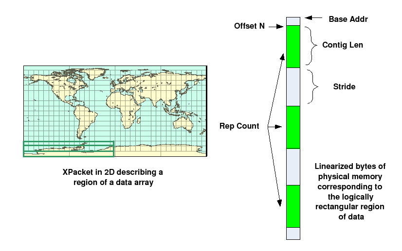 |
The Communication Table (CommTable) class encapsulates which other PETs this PET needs to talk to, and in what order. There are create and destroy methods, methods to set that a PET has data either to send or receive, and query routines that return an answer to the question 'which PET should I exchange data with next'.
The Route Table (RTable) class contains a list of XPackets to be sent and received from other PETs. It has create/destroy methods, methods to add XPackets to the list for each PET, and methods to retrieve the XPackets from any list.
The top level class is a Route. A Route object contains a send RTable, a recv RTable, a CommTable, and a pointer to a Virtual Machine. The VM must include all PETs which are participating in this communication. The Route methods include create/destroy, setting a send or recv XPacket for a particular PET, and some higher level functions specific to each type of communication, for example RoutePrecomputeHalo or RoutePrecomputeRedist. These latter functions are where the XPackets are actually computed and added to the Route table. Each DE computes its own set of intersections, either source or destination, and fills its own corresponding PET table. The Route methods also include a RouteRun method which executes the code which actually traverses the table and sends the information between PETs.
A RouteHandle class is a small helper class which is returned through the public API to the user when a Route is created, and passed back in through the API to select which precomputed Route is to be executed. A RouteHandle contains a handle type and a pointer to a Route object. In addition, for use only by the Regrid code, there is an additional Route pointer and a TransformValues pointer. (TransformValues is an internal class only used by the Regridding code.) If the RouteHandle describes the Route for a FieldBundle, then the RouteHandle can contain a list of Routes, one for each Field in the FieldBundle, and for Regrid use, a list of additional Routes instead of a single Route. There is also a flag to indicate whether a single Route is applicable to all Fields in a FieldBundle or whether there are multiple Routes. The RouteHandle methods are fairly basic; mostly accessor methods for getting and setting values.
While intended for any distributed data communication method, the current implementation only builds a Route object for the halo, redist, and regrid methods. Scatter, Gather, AllGather, and AlltoAll should have the option of building a Route for operations which are executed repeatedly. This should only require writing a Precompute method for each one; the existing RouteRun can be invoked for these operations. (This is a lack-of-implementation-time issue, not a design or architecture issue.)
The original design included automatic detection of different Routes and internal caching, so the user API did not have to include a RouteHandle object to identify which Route was being invoked. However, users requested that the framework not cache and that explicit RouteHandle arguments be created and required to invoke the distributed data methods. Nothing prevents this code from being revived from the CVS repository and reinstated in the system, should automatic caching be desired by future users.
The current distributed methods have 2 related but distinct interfaces which differ in what information they require and whether they use RouteHandles:
The current CommTable code executes one very specific communication strategy based on input from a user who did extensive timing measurements on several different hardware platforms. Rather than broadcasting all data at once asychronously, it selects combinations of pairs of processors and has them execute a SendRecv operation, which does both a data send and a data receive in a single call. At each step in the execution, different pairs of processors exchange data until all pair combinations have been selected.
The table itself must be a power of 2 in size; the number of PETs is rounded up to the next power of 2 and then all entries for PETs larger than the actual number are marked as no-ops.
There are many alternative execution strategies, including a completely asynchronous execution, in numeric PET order, without computing processor pairs. Also single-direction communications are possible (only the Send XPackets are processed, or only the Receive XPackets) in either a synchronous or asynchronous mode. This would not require any changes to the XPacket or RTable classes, but would require writing a set of alternative RouteRun methods.
The current RouteRun routine has many possible performance options for how to make the tradeoff between time spent packing disjoint memory blocks into a single buffer to minimize the number of sends, verses simply sending the contiguous blocks without the pack overhead. The tradeoffs are not expected to be the same on all systems; hardware latency verses bandwith characteristics will differ, plus the underlying communication software (MPI, shared memory, etc) will change the performance. Also the size of the data blocks to be sent, the amount of contiguity, and limits on the number of outstanding communication buffers all affect what options are best.
The ESMF_RouteOptions are listed in 31.3; the following description contains more implementation detail about what each of the options controls inside the execution of a Route. Note that the options do not affect the creation of a Route, nor any of the Precompute code, and can optionally be changed each time the Route is run.
Packing options:
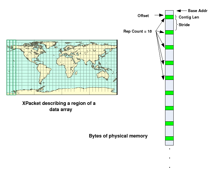 |
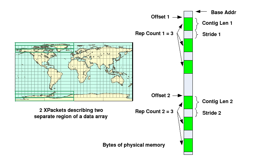 |
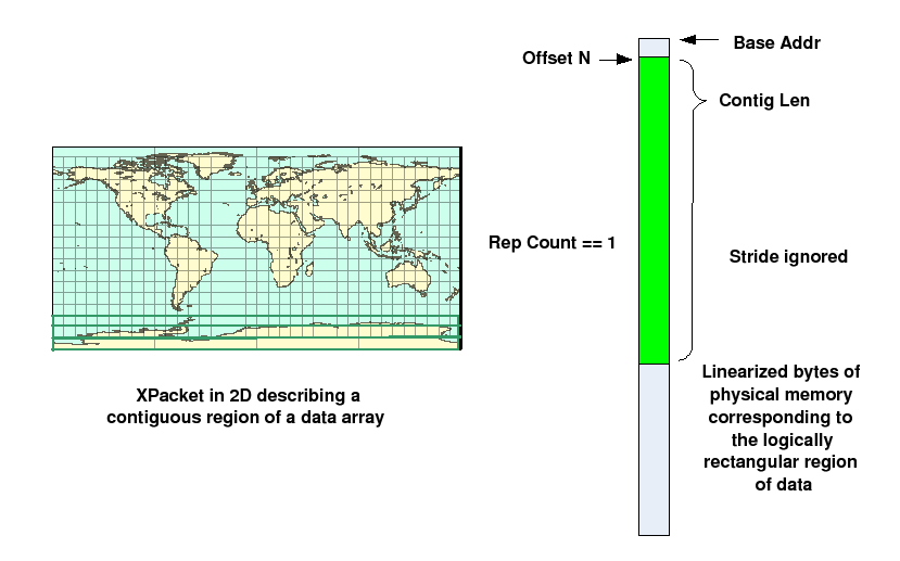 |
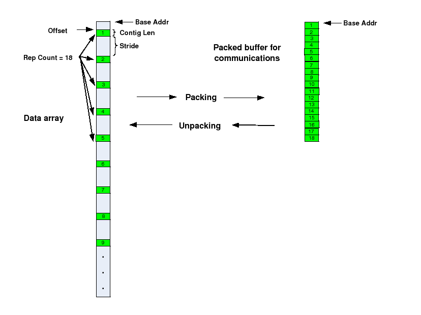 |
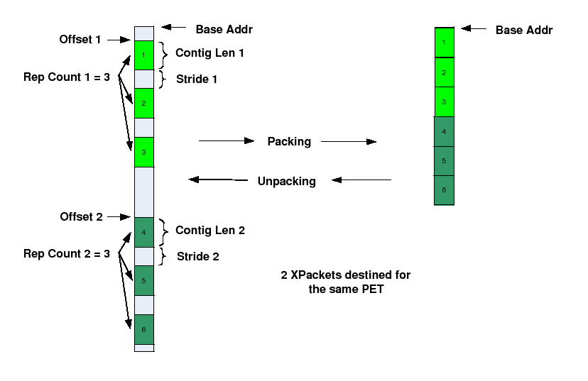 |
The following options refer to the internal strategy for executing the route and not to whether the user-level API call returns before the route has finished executing. The current system only implements user-synchronous calls; asynchronous calls are on the to-be-written list.
FieldBundle-level communication calls have additional packing options under certain circumstances. FieldBundles are groups of Fields which share the same Grid, but they are not required to share the same data types, data ranks, nor relative data locations. FieldBundles in which these things are the same in all Fields are marked inside the bundle code as being congruent. At communication store time FieldBundles which have congruent data in all the Fields have the option of packing all Field data together into fewer communication calls which generally is expected to give better performance. Fields where the data is not of the same type or perhaps not the same number of items (e.g. different rank, vertex-centered data vs. cell centered data) can in theory also be packed but in fact the code becomes more complicated, and in the case of differing data types may cause system errors because of accessing data on non-standard byte offsets or putting mixing integer data with floating data and causing NaN (not a number) exceptions. In this case, the conservative implementation strategy is to construct a separate Route object for each Field, all enclosed in the same RouteHandle. Inside the FieldBundle communication code the execution for both types of FieldBundles is identical for the caller, but inside the congruent FieldBundle code calls the ESMF_RouteRun() code once and all communication for all Fields in the FieldBundle is done when it returns. The non-congruent FieldBundles execute a separate ESMF_RouteRun() call for each Field and return to the user when all Field data have been sent/received.
There are comments in the code for an intermediate level of optimization in which the FieldBundle code determines the smallest number of unique types of Fields in the FieldBundle, and all same types share the same Route object, but this has not been implemented at this time. Once the existing code has been in use for a while, whether this is useful or needed may become more clear.
The precompute code for all operations must have enough information to compute which parts of the data arrays are expected to be sent to remote PETs and also what remote data is expected to be received by this PET.
These computations depend heavily on what type of distributed method is being executed. The regridding methods are described in detail separately in the Regrid Design and Implementation Notes section. The halo and redistribution operations are described here.
The following is a simplified UML diagram showing the structure of the public RouteHandle class. See Appendix A, A Brief Introduction to UML, for a translation table that lists the symbols in the diagram and their meaning.
![\includegraphics[]{RouteHandle_obj}](img94.png)