NUOPC Interoperability Layer
Overview
The National Unified Operational Prediction Capability (NUOPC) is a consortium of Navy, NOAA, and Air Force modelers and their research partners. It aims to advance the weather prediction modeling systems used by meteorologists, mission planners, and decision makers. NUOPC partners are working toward a common model architecture - a standard way of building models - in order to make it easier to collaboratively build modeling systems. To this end, they have developed the NUOPC Layer that defines conventions and a set of generic components for building coupled models using the Earth System Modeling Framework (ESMF).
Download and Install
The NUOPC Layer is included with the ESMF distribution. No separate download or installation is required.
Documentation
See the main ESMF documentation page for links the NUOPC technical documentation.
Features
Four Basic Building Blocks
NUOPC applications are built on four basic kinds of generic components:
-
Driver: Provides a harness for Models, Mediators, and Connectors, coordinating their nitialization and driving them during the application time loop.
-
Model: Typically implements a specific physical domain, e.g. atmosphere, ocean, sea ice, waves, etc.
-
Mediator: Used for custom coupling code (flux calculations, averaging, etc.) between multiple Models.
-
Connector: Connects pairs of components, e.g. Model to/from Model, or Model to/from Mediator, and executes simple transforms (i.e., regrid or redistribution).
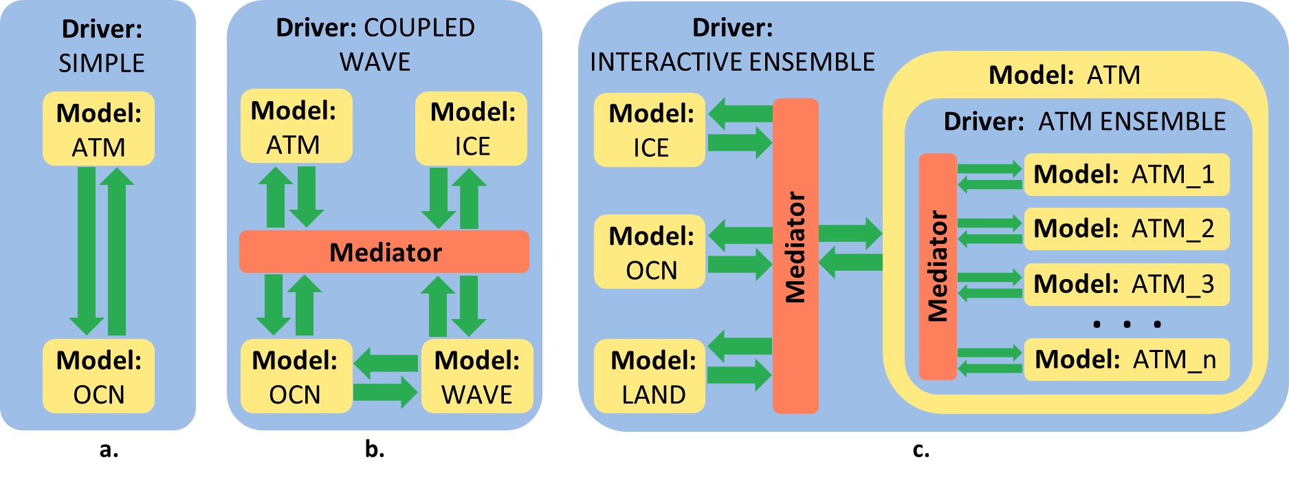
Many Architectural Options
The four basic building blocks can be arranged in many different ways. This allows applications to implement a wide range of model architectures, including ensembles, component hierarchies, and simple connections.
Field Brokering
A field dictionary supports field brokering and compliance checking between components.
Initialize Sequence
The initialize sequence implemented by the NUOPC Layer supports various levels of component negotiation. This includes field brokering between producer and consumer components, resolving data dependencies between components, transferring model grids, and negotiating pointer sharing.
A typical sequence of initialization phases is shown in the diagram below for the coupled ATM-OCN model.
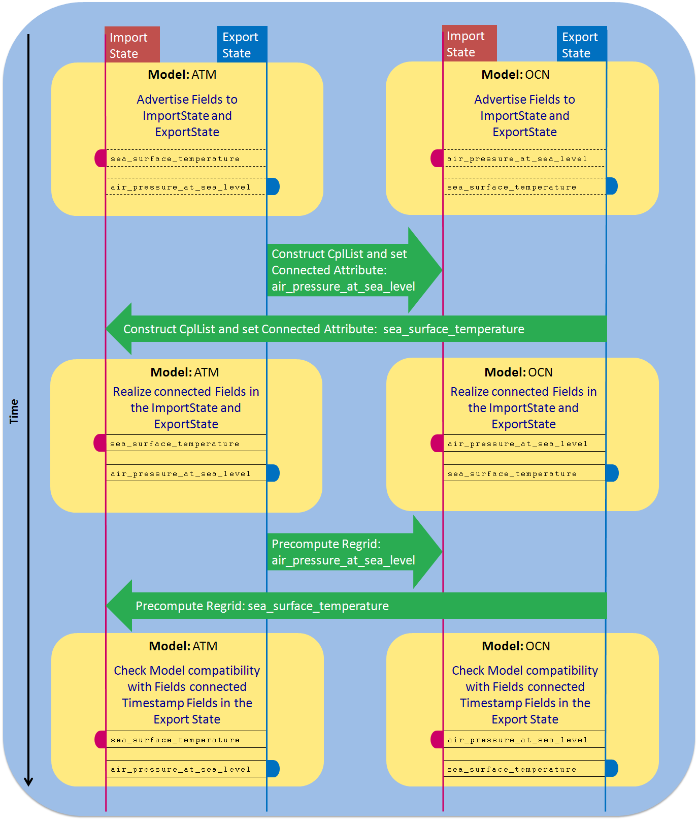
The diagram above shows an ATM preparing to send
air_pressure_at_sea_level to an OCN, and an OCN preparing to send
sea_surface_temperature to an ATM. The Import States (Fields to be
received) for the Models above are indicated with a red box and line,
and the Export States (Fields to be sent) by a dark blue box and line.
The NUOPC Driver creates a unique pair of Import and Export States for every Model, Mediator, and Driver component that is plugged into the Driver harness. Connector components on the other hand do not own their Import and Export States - instead they provide connections between States owned by other components.
Typically the first action in the initialize phase sequence is for the Model components to “advertise” Fields in their Import and Export States. These Fields may be without actual memory allocations at this point, which is indicated by the dashed line around the Field boxes. The requirement is that the required NUOPC Field metadata is present. The generic Connectors use the advertised Fields to construct connection maps between the components.
In the next phase, the Model components use this information to “realize” connected Fields by associating actual memory allocations. This is indicated by a change to a solid line around the Field boxes.
Once the Fields in the Import and Export States have been connected and realized, the Connector components enter an initialization phase to precompute any required Regrid or Redist operations. Finally the Model components enter initialization phases to check compatibility of inputs and outputs, and then to apply initial time stamps on the Fields in the Export State.
Run Sequence
The NUOPC Layer is capable of implementing many different coupling schemes. To do so, every NUOPC Driver component parameterizes the dynamic aspect of driving the Model components in the form of a derived type called NUOPC_RunSequence. Each RunSequence is associated with a Clock for its own time stepping, and a chain of RunElements. A Driver component can store multiple run sequences, and one run sequence can call into another run sequence. This allows the implementation of very complex sequences with multiple time scales.


Sequential vs. Concurrent Components
The NUOPC Driver facilitates both sequential and concurrent execution of its children. The actual mode of execution between the children is determined by the combination of a technical and a scientific restriction. On the technical side, concurrent execution of any number of components is supported as long as they are all defined on mutually exclusive petLists. The petList of each child component can be set during an optional specialization of its parent Driver. As soon as two components share one common PET (Persistent Execution Thread) they will run sequentially, for the simple technical reason that a PET can only execute one stream of instructions at a time.
Even when components are defined on mutually exclusive petLists, scientific restrictions will typically limit the extent to which they can truly execute concurrently. The scientific restrictions enter the system through data dependencies between components. In the simplest case there will be an associated coupling interval that determines how strongly such a data dependency synchronizes components that can in principle proceed independently, but need forcing fields from the other components from a previous time step. More complicated semi-implicit, leap-frog, or fully implicit schemes result in even stronger scientific restrictions.


Multiple Instances of Components
The NUOPC Driver instantiates every child Component as its own object. This means that multiple instances of the same Component are supported. For example the same ATM component code can be instantiated multiple times, each instance becoming an independent component object with its own private memory, data distribution and petList.
Being able to instantiate and manage the same component code multiple times within the same Driver can be leveraged in model ensembles as well as nested models. There are three nesting examples available: NestingSingleProto, NestingMultipleProto, and NestingTelescopeMultipleProto.
Component Hierarchies
Components that interact as Models on one level can be implemented as Drivers with their own child Model components on a lower level. For instance, the ATM Model component can be implemented as a Driver for its child components: dynamics and physics. At the same time the ATM component can be used as a Model component by its parent component.

Another application of component hierarchies is that of interactive ensembles. Here multiple Model components (maybe multiple instances of the same Model, or instances of different Models) are executing while they may appear as a single Model to the outside. For example an ensemble of ATM Models may interact with a single OCN Model. In this case it may be very convenient to pack all of the complexity of the ATM ensemble into an encapsulating Driver component. To the outside, i.e. for interaction with the OCN Model, the ensemble component appears as a simple ATM Model.
Prototype Applications
This section contains descriptions and links to example codes that are available from the NUOPC prototype repository. The prototype codes demonstrate how the four building blocks of the NUOPC Layer can be used to implement a number of different architectures. For each architecture class the “relationship diagram” shows the number and types of components involved, and how they relate to each other. The “coupling diagram” shows the temporal aspect of the coupling between model components along the model time axis. In a coupling diagram the same connectors (green arrows) show up multiple times.
The sample prototypes linked on this page correspond to the ESMF/NUOPC 8.0.1 release. There are dozens of other documented prototypes in the repository!
# clone all NUOPC prototypes for 8.0.1 release
git clone https://github.com/esmf-org/nuopc-app-prototypes --branch ESMF_8_0_1
| Description / Links | Relationship Diagram | Coupling Diagram |
|
A single NUOPC_Model component is driven by a NUOPC_Driver. About the coupling: A single model component is being called by the driver in regular intervals. There is no coupling. |

|
|
|
ATM-OCN coupling through generic connectors. The dependencies in both coupling directions are explicit.
About the coupling: Simple explicit coupling requires that ATM and OCN Fields are exchanged in both directions at the beginning of each coupling interval. This exchange is accomplished via connector components. |

|
|
|
ATM-OCN coupling through a mediator. The dependencies in both coupling directions are explicit.
About the coupling: Connector components transfer ATM and OCN Fields to the Mediator at the beginning of each coupling interval. The Mediator processes this input and connector components transfer the Mediator output back to the model components. The model components then integrate forward for one coupling interval before the same process is repeated. |

|
|
|
ATM-OCN-LND coupling through generic connectors. The dependencies in all coupling directions are explicit.
About the coupling: All three model components participate in an all-to-all exchange via the six connector components at the beginning of every coupling interval. |

|
|
|
ATM-OCN coupling through generic connectors with semi-implicit dependencies: the OCN-to-ATM coupling direction is explicit, while the ATM-to-OCN coupling direction is implicit. The OCN requires the ATM forcing fields for time t+tc before it can take its t → t+tc forward step (tc is the coupling interval). This scheme is also referred to as leap-frog coupling. About the coupling: The leap-frog coupling scheme requires that the connector in one direction (here ATM⇒OCN) is called after the producer (here ATM) has taken its forward step, but before the consumer (here OCN) can take its foward step. The connector in the other direction is executed when both model components have reached the same model time. |
|
|
|
ATM-OCN coupling through generic connectors with implicit dependencies in both coupling directions. The ATM model provides Run phases for up- and down-sweep, and the OCN provides Run phases for slow and fast processes. About the coupling: The ATM model implements an implicit scheme that requires "down" and "up" sweeps through the atmosphere. However, at the interface, i.e. after each "down" sweep it must couple to the fast processes on the OCN side (sea-ice) before it can continue with the "up" sweep. Connectors are used to correctly exchange the Fields between these processes. This process continues until the slow coupling interval has been reached. The connector ensures that the ATM Fields are available when the OCN integrates forward its slow processes. |
|
|
|
ATM-OCN-RTM coupling through generic connectors. The dependencies in all coupling directions are explicit. Coupling of ATM and OCN with the RTM component is on a different (longer) timescale as the ATM-OCN coupling. About the coupling: The ATM-OCN coupling cycle is a simple explicit scheme with a connector component for each direction, executed every 3 hours. The connectors for ATM⇒RTM and RTM⇒OCN coupling are called every 24 hours. |

|
|


